Table of Contents
Advertisement
Advertisement
Table of Contents

Subscribe to Our Youtube Channel
Related Manuals for TECSYSTEM NT511Series


Summary of Contents for TECSYSTEM NT511Series
- Page 1 INSTRUCTION MANUAL NT511 1MN0138 REV. 0 operates with ISO9001 certified quality system TECSYSTEM S.r.l. 20094 Corsico (MI) Tel.: +39-024581861 Fax: +39-0248600783 http://www.tecsystem.it R. 1.1 01/08/19 ENGLISH “Translations of the original instructions”...
-
Page 2: Table Of Contents
INTRODUCTION First of all we wish to thank you for choosing to use a TECSYSTEM product and recommend you read this instruction manual carefully: You will understand the use of the equipment and therefore be able to take advantage of all its functions. - Page 3 PAGE ………………………………….. 8) RS485 MODBUS (only for NT511 Modbus or AD) INTRODUCTION TO THE MODBUS INSIDE — ………………………………….. MODULE — ………………………………….. OPERATING NOTES — ………………………………….. DATA TRANSMISSION ON MODBUS NETWORK — ………………………………….. RS485 ELECTRICAL CONNECTIONS — …………………………………..
-
Page 4: Safety Requirements
Position on a stable surface, far from any possible vibrations. Position the unit as far as possible from intense magnetic fields. REPAIRS For any fault, always use qualified personnel. Modifying of the unit boards generate the automatic forfeiture of the warranty. TECHNICAL INFORMATION Mail: ufficiotecnico@tecsystem.it — tel: 02/4581861 NT511 ASERIES... -
Page 5: Accessories
ACCESSORIES Tthe following object are present inside the box: Control unit Start guide and QR code Start guide and QR code 2 supply terminal and RS485 (*) 3 poles pitch 5 Code: 2PL0367 - Screws tightening torque 0.5Nm 1 relay terminal 9 poles pitch 5 Code: 2PL0376- Screws tightening torque 0.5Nm 1 relay terminal output M1 to M6 7 poles pitch 5 Code: 2PL0373- Screws tightening torque 0.5Nm... -
Page 6: Technical Specifications
NT511 NT511 MODBUS NT511 AD TECHNICAL SPECIFICATIONS POWER SUPPLY 230VAC±10% 230VAC±10% 230VAC±10% Supply rated values 50/60Hz 50/60Hz 50/60Hz Absorption (without fans) INPUTS ● ● ● 4 inputs for RTD sensors, Pt100 type with 3 wires (max section 2.5mm²) ● ● ●... -
Page 7: Display
TECHNICAL SPECIFICATIONS NT511 NT511 MODBUS NT511 AD ● ● ● Frontal film polycarbonate IP50 ● ● ● Steel painted housing ● ● ● Digital linearity of sensor signal ● ● ● Self-diagnostic circuit Protection treatment of the electronic part Option Option Option DISPLAY AND DATA MANAGEMENT... -
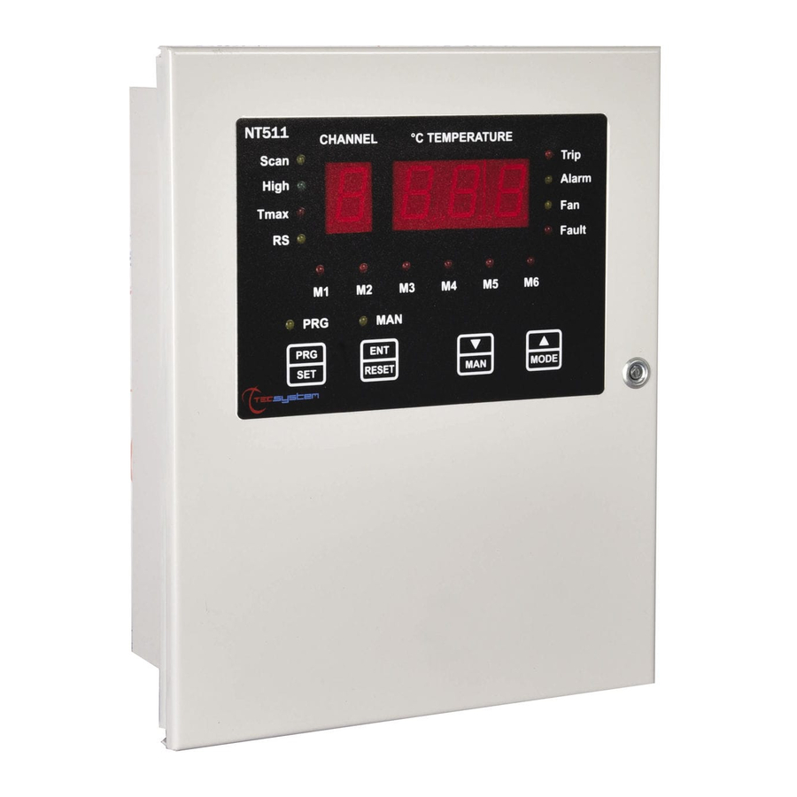
Page 8: Front Panel
FRONT PANEL 1MN0139 REV. 0 Control unit series FAULT M3 (red) LED 1-digit channel display (CHn) Enter/Reset button 3-digits temperature display Manual mode fan operating (yellow) LED TRIP (red) LED FAULT M2 (red) LED ALARM (yellow) LED Programming / Setting key FAN (yellow) LED Entering PRG (yellow) LED FAULT (red) LED (UNIT) -
Page 9: Operating Program Control
DISPLAY The first display is dedicated to the monitored channel. The second display to the temperatures. Pressing the MODE key, the display modes can be set: SCAN: the monitoring unit displays all the activated channels scanning every 2 seconds. ... - Page 10 Fix the unit securely with the screws. 1MN 0138 REV. 0 3 holes Ø 22mm for electrical cable Dimensions and fixings NT511 ASERIES...
-
Page 11: Electrical Connections
ELECTRICAL CONNECTIONS NT511 POWER-RELE’ CARD 1MN0140 REV. 0 1, 5Amp x 6 MAX Ф Output relay with 5A-250Vac-res COS =1 contacts. Ф F1 2A 250V output M1 (5x20 fast) fuse 2A 250V output M6 (5x20 fast) fuse F2 2A 250V output M2 (5x20 fast) fuse Input power supply 0.5A 250V fuse F3 2A 250V output M3 (5x20 fast) fuse Relè... - Page 12 ELECTRICAL CONNECTIONS NT511 CPU-DISPLAY CARD Pt100 CONNECTION EXAMPLE 1MN0141 REV. 0 Pt100 3 wires CH1-CH2-CH3-CH4 inputs RS485 Modbus RTU output (option) 4.20mA output (option) Note: before connecting sensors to the control unit, read the Measurement signal transfer paragraph on page 16. NT511 ASERIES...
-
Page 13: Power Supply
POWER SUPPLY The NT511 control unit has 230Vac ±10% 50-60Hz power supply (terminal 36-38). The ground must always be connected to terminal 37. When the unit is supplied directly by the secondary of the transformer to protect, it can be burnt out by strong overvoltages. This happens if the main switch is closed and the transformer has no load (blank test). -
Page 14: Programming
PROGRAMMING NT511 MODBUS INSIDE /AD STEP PRESS EFFECT PRESS NOTES Keep the PRG key pressed until the display shows PRG, PRG led turns on The ALARM threshold for CH 1-2-3 is displayed Default 90°C Set the desired threshold, the Alarm LED flashes. The TRIP threshold for CH 1-2-3 is displayed and the Trip LED flashes. -
Page 15: Programming Notes
We recommend you check the unit's programming before starting the device. The default parameters set by TECSYSTEM might not match your requirements. Programming the device is the end user's responsibility, the settings of the alarm thresholds and the enabling of the functions described in this manual must be checked (by a specialized engineer) according to the application and features of the system the control unit is installed on. -
Page 16: Temperature Sensors
/ electrical fault of the Pt100 sensors c) damage to the Pt100 inputs of the control unit. TECSYSTEM S.r.l. has designed its own special cable to transfer the measurement signals, CEI-compliant, with all the protection requirements provided for: model CT-ES 1MN0035 REV. -
Page 17: Temperature Sensor Diagnostics
The activation of FCD (see page 25) must always be operated taking into account the system working conditions. CAL message display: it appears when damage is found in the measurement circuit. The temperature values displayed might be incorrect. Return the control unit to TECSYSTEM for repairs. PROGRAMMED DATA DIAGNOSTICS In case of failure of the internal memory or corruption of programmed data, just after switching on, Ech appears with the relevant Fault contact. -
Page 18: Introduction To The Modbus Inside
RS485 MODBUS OUTPUT (ONLY FOR NT511 MODBUS AND AD) INTRODUCTION TO THE MODBUS INSIDE MODULE The MODBUS INSIDE expansion module is built in the monitoring unit and allows data transfer on a RS485 line with MODBUS RTU protocol, max 32 devices. OPERATING NOTES For the module to work correctly, it is necessary to set the RS485 network set-up parameters: address, baud rate, parity bit. -
Page 19: Function Code
FUNCTION CODE The ModBus module supports the following function codes: - holding register reading (10) - register multiple writing (10) If ModBus receives a message and a CRC error is detected, no answer is given. CODE 3 (10) Request: Slave address, code 3 , Starting address HI, Starting address LO, Number of Point HI, Number of Point LO, Crc LO, Crc HI. -
Page 20: Error Codes
ERROR CODES (exception codes) In case of a wrong request, ModBus will answer with modified codes and codified errors according to the following: - Unsupported function code - Wrong data address - Wrong data (for instance length) POLLING FREQUENCY We recommend polling frequencies equal to or greater than 1 second are adopted. More frequent polling can overload the system without any benefit. - Page 21 Address Address Primary Data HI Data LO Note tables (10) (10) Holding Setting Ch1 register Holding Setting Ch2 register (See note 2) Holding Setting Ch3 register Holding Setting Ch4 register Holding T. max Ch1 register Holding T. max Ch2 register Range 0-200°...
- Page 22 Address Address Primary Data HI Data LO Note tables (10) (10) Holding Trip Set-point Ch1 register Holding Trip Set-point Ch2 register Holding Trip Set-point Ch3 register Holding Trip Set-point Ch4 register Fan-On Set-point Holding register Fan-On Set-point Holding register Fan-On Set-point Holding register Fan-On Set-point...
- Page 23 Address Address Primary Data HI Data LO Note tables (10) (10) 0=ch1, 1=ch2, Holding 4.20 output 2=ch3, 3=ch4, register 8=scan, 9=hot Num. Enable Channels –1 Holding NUM_CH register ES: if N°=2 enable channels are 3 Holding NUM_FAN Num. enable Fans register Holding FAULT_FAN...
-
Page 24: Crc Calculation
When the flag is active it means that the fan, even if supplied, is not working because it does not detect the current flowing (presence of no-load voltage). It is assumed that the fan is faulty or improperly connected. CRC CALCULATION The protocol includes 2 CRC-16 bytes in each transmission. - Page 25 The Product purchased is covered by the manufacturer's or seller's warranty at the terms and conditions set forth in the "Tecsystem s.r.l's General Conditions of Sale", available at www.tecsystem.it and / or in the purchase agreement. The warranty is considered valid only when the product is damaged by causes attributable to TECSYSTEM srl, such as manufacturing or components defects.
-
Page 26: Troubleshooting
Returning used electrical devices: contact TECSYSTEM or your TECSYSTEM agent for information on the correct disposal of the devices. TECSYSTEM is aware of the impact its products have on the environment and asks its customers active support in the correct and environmentally-friendly disposal of its devices.
Need help?
Do you have a question about the NT511Series and is the answer not in the manual?
Questions and answers