
Related Manuals for Globalstar STINGR


Summary of Contents for Globalstar STINGR
- Page 1 Revision 1.0 STINGR Users Manual STINGR Users Manual Revision 1.0 Subject To Change without Notice P a g e 09/30/15...
-
Page 2: Table Of Contents
Introduction ..................................4 Purpose ................................... 4 Applicable Documents ............................4 Description ................................4 Application ..................................5 Theory of Operation for Globalstar Simplex ......................5 Block Diagram ................................. 8 Physical Charactersistics ..............................9 Reference Design ................................13 Schematic ................................14 PCB ..................................15 BOM .................................. - Page 3 “Turn OFF GPS” command ........................37 5.2.3.12 “Turn On GPS Pass-through” command ....................37 5.2.3.13 “Turn Off GPS Pass-through” command ....................38 STINGR Serial Test Commands ..........................39 5.3.1 “Transmitter Test” command ........................39 5.3.2 “Self Test” command ............................ 40 Example CRC calculation routines for serial packets ....................
-
Page 4: Introduction
NMEA 0183 Standard for Interfacing Marine Electronic Devices 1.3 Description The STINGR is a simplex Satellite transmitter designed to send small packets of user defined data to a network of low earth orbiting (LEO) satellites using the Globalstar simplex satellite network. The received data is then forwarded to a user defined network interface that may be in the form of an FTP host or HTTP host where the user will interpret the data for further processing. -
Page 5: Application
2.1 Theory of Operation for Globalstar Simplex The STINGR operates on the Globalstar LEO satellite network. LEO (Low Earth Orbit) means that there are a number of satellites in low earth orbit that constantly orbit the planet and can communicate with Globalstar devices that are within range of its current position. - Page 6 Globalstar network. The default value for the number of redundant transmissions per message is 3. This means that each message sent to the STINGR will be transmitted 3 times. Each transmission will contain the exact same data payload. The redundant transmissions of each message will be sent on a randomized 5-minute nominal interval.
- Page 7 Revision 1.0 STINGR Users Manual The transmission sequence for a two-packet message using the default setting of 3 redundant transmissions is shown below. For normal conditions where the transmitter has an open view of the sky, this will result in a better than 99% chance that the message will be received.
-
Page 8: Block Diagram
RF transmissions. The STINGR has internal regulators which provide separate power for the digital, RF and GPS circuitry. This provides the capability to leave the STINGR in a low power consumption state when the transmitter RF section and the GPS section are idle. The internal RF power supply is a high power supply which is only required while the STINGR is transmitting a data packet. -
Page 9: Physical Charactersistics
Revision 1.0 STINGR Users Manual 3 Physical Charactersistics Figure 5 Top View Revision 1.0 Subject To Change without Notice P a g e 09/30/15... - Page 10 Revision 1.0 STINGR Users Manual Figure 6 Recommended PCB footprint layout Revision 1.0 Subject To Change without Notice P a g e | 10 09/30/15...
- Page 11 Revision 1.0 STINGR Users Manual NAME TYPE Description Ground RESERVED RESERVED Do NOT connect Output 3.0V Open Collector, weak internal pull-up, may be pulled up to 5V max external Input 3.0V (5V tolerant), weak internal pull-up Input 3.0V (5V tolerant), weak internal pull-up Output 3.0V Open Collector, weak internal pull-up, may be pulled up to 5V max external...
- Page 12 The STINGR is inactive between transmissions but is not transmitting Transmit Mode The STINGR is transmitting an RF packet GPS Standby Mode The STINGR is Standby Mode while in Proprietary Track mode with an interval of 30 minutes or less Table 4 – Operating Current Parameter Test Conditions...
-
Page 13: Reference Design
USB interface, and test mode switches. Since the battery is located on the same board as the STINGR, no decoupling capacitor is required on the VBATT input. However, if there are battery leads, lengthy power distribution, or noise sources present, a suitable decoupling capacitor might be appropriate. -
Page 14: Schematic
Revision 1.0 STINGR Users Manual 4.1 Schematic Revision 1.0 Subject To Change without Notice P a g e | 14 09/30/15... -
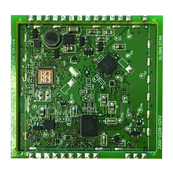
Page 15: Pcb
Revision 1.0 STINGR Users Manual 4.2 PCB 4.3 BOM Manufacturer Part Number Designator Description Manufacturer Quantity BC2/3AE Multicell Battery GRM155R71A104KA01D C1, C3 CAP 0402 CER 100NF 10V X7R +/-10% MURATAELEC 04026D105KAT2A CAP 0402 CER 100NF 10V X7R +/-10% AVXCORP SP0503BAHTG... -
Page 16: Application Programming Interface
DTE and, if applicable, executes the command. In order to wake the STINGR from sleep mode and to indicate the end of the serial packet, each serial packet must be framed by activating RTS before the first byte of the command and deactivating RTS after the last byte of the command. -
Page 17: Serial Packet Mode
< 125 ms Command Response 1. Lower RTS 2. Wait for CTS to go low 3. Send Command to STINGR 4. Raise RTS 5. STINGR raises CTS 6. STINGR sends response 5.2 Serial Packet Mode This mode is the legacy mode of operation as implemented in the STX2 and STX3 which consists of binary data packets. -
Page 18: Stx3 Legacy Serial Packet Commands
If an improperly formatted command is received, the STINGR will return a NAK response: AA 05 FF A1 CB 5.2.2.1 Send Data (0x00) The Send Data command requests the STINGR to send from 1 to 144 data bytes over the Globalstar Simplex network. 0x00 payload... -
Page 19: Abort Transmission (0X03)
AA 05 03 42 F6 Response: AA 05 03 42 F6 5.2.2.4 Query Bursts Remaining (0x04) The Query Bursts Remaining command requests the STINGR to return the current number of bursts remaining the current message transmit sequence over the Globalstar Simplex network. 0x04 Leader... -
Page 20: Setup (0X06)
AA 07 05 01 07 E0 6A Where the firmware version returned is: 5.2.2.6 Setup (0x06) The Setup command requests the STINGR to use the specified setup parameters. These are stored in non-volatile memory. 0x06 Command: header len 04 RESERVED... -
Page 21: Query Hardware Version (0X09)
0x18 = 24, 24 x 5 = 120 seconds Maximum Burst Interval: 0x30 = 48, 48 x 5 = 240 seconds 5.2.2.8 Query Hardware Version (0x09) The Query Hardware Version command requests the STINGR to return the current hardware version information. 0x09 Leader CRC1 CRC2... - Page 22 Revision 1.0 STINGR Users Manual Where: Device Code : Always 1 for STINGR Silicon Revision: Simplex Silicon revision CPU Revision: Simplex CPU revision Radio Revision: Simplex Radio revision Example Response: AA 0A 09 00 01 8F 62 62 F7 58 Where the revision information returned is: ...
-
Page 23: Stingr Serial Packet Commands
In track mode, the STINGR does not send bursted (redundant) messages. It will transmit a single transmission for each interval. If it is desired to send bursted messages, use the Send Data (0x00) or Send Redundant Burst with GPS (0x33) commands. -
Page 24: Proprietary Motion Activated Track" Command
3. Motion Activated Tracking with Dock mode In track mode, the STINGR does not send bursted (redundant) messages. It will transmit a single transmission for each interval. If it is desired to send bursted messages, use the Send Data (0x00) or Send Redundant Burst with GPS (0x33) commands. - Page 25 Revision 1.0 STINGR Users Manual The following table summarizes the standby mode supply current for different modes Operating Mode Standby Current Continous Tracking <= 30 minute interval GPS Standby Mode + Standby mode supply current w/Accelerometer Continous Tracking > 30 minute interval Standby mode supply current w/Accelerometer Motion Activated/Dock Tracking <= 30 minute interval...
-
Page 26: Set Tracking Preferences" Command
3. Motion Activated Tracking with Dock mode In Continuous Tracking mode, the STINGR will obtain and transmit GPS location along with the specified payload on the interval specified in the Proprietary Tracking command until the Cancel Proprietary Tracking command is received. - Page 27 Revision 1.0 STINGR Users Manual 0 - 7 Leader Always a value of 0xAA. 0 - 7 Length 0x08 Command 0 - 7 Code. 0x12 = Set Tracking Options Bit 0: RESERVED (always set to 0) Bit 1: RESERVED (always set to 0)
-
Page 28: Get Tracking Preferences" Command
Revision 1.0 STINGR Users Manual 5.2.3.4 “Get Tracking Preferences” command This command will return the selected mode of operation for the Proprietary Track command. Set Tracking Preferences command format Byte Bits Parameter Description 0 - 7 Leader Always a value of 0xAA. -
Page 29: Update Proprietary Track Data" Command
Revision 1.0 STINGR Users Manual 5.2.3.5 “Update Proprietary Track Data” command This command is used to change the user programmable data in a proprietary track message. If a proprietary track session is not in progress, it is ACK’d but will do nothing. -
Page 30: Cancel Proprietary Track/Proprietary Motion Activated Track" Command
This command is used to initiate a redundant bursted message (as setup in STX configuration). Bytes 1 – 6 of the first packet of the message shall contain latitude and longitude in standard Globalstar 24-bit format. Since each on-air message must be a multiple of 9 bytes, the message will contain up to 15 9-byte packets depending on the size of the payload. - Page 31 Revision 1.0 STINGR Users Manual Send Redundant Burst with GPS command format Byte Bits Parameter Description 0 - 7 Leader Always a value of 0xAA. 0 - 7 Length Variable 0x08 – 0x90 (144 bytes) 0 - 7 Command Code.
- Page 32 Revision 1.0 STINGR Users Manual Where: Payload Byte 0: 0x01 Payload Byte 7: 0x02 Payload Byte 8: 0x03 Payload Byte 9: 0x04 Payload Byte 10: 0x05 Payload Byte 11: 0x06 Payload Byte 12: 0x07 ...
-
Page 33: Get Status" Command
Revision 1.0 STINGR Users Manual 5.2.3.8 “Get Status” command This command will return the status of the STINGR module. Get Status command format Byte Bits Parameter Description 0 - 7 Leader Always a value of 0xAA. 0 - 7 Length... - Page 34 0 - 7 Current GPS 0: (No Fix) Level 1: (At least a 2D Fix) 2: (At least a 3D Fix) 3: (Globalstar extra Criteria based on testing) Revision 1.0 Subject To Change without Notice P a g e | 34 09/30/15...
-
Page 35: Query Location" Command
Revision 1.0 STINGR Users Manual 28-29 0 - 15 Number of Number of seconds since the Device successfully obtained a GPS fix seconds since for any reason. last GPS fix 0 - 7 Last This field will be 0 if the last transmission was sent without a GPS fix transmission and 1 if it was sent with a GPS fix. -
Page 36: Turn On Gps" Command
Revision 1.0 STINGR Users Manual This response is sent to response to a “Query Location” command. Query Location Response Byte Bits Parameter Description 0 – 7 Leader Always a value of 0xAA. 0 – 7 Length 0x0C 0 – 7 Command Code. -
Page 37: Turn Off Gps" Command
Revision 1.0 STINGR Users Manual Response: AA 05 FD B3 E8 5.2.3.11 “Turn OFF GPS” command This command will turn off the GPS engine. Turn Off GPS Byte Bits Parameter Description Leader Always a value of 0xAA. Length 0x06 Command Code. -
Page 38: Turn Off Gps Pass-Through" Command
Revision 1.0 STINGR Users Manual Example NMEA messages: $GPGSA,A,3,28,17,30,06,01,03,11,07,13,19,,,1.5,0.9,1.2*3A $GPGSV,3,1,12,28,65,044,42,17,60,319,45,30,40,177,46,06,34,203,40*7D $GPGSV,3,2,12,01,26,043,42,03,18,090,41,11,13,046,38,07,10,162,39*7B $GPGSV,3,3,12,13,09,252,42,19,05,059,30,02,03,213,34,24,02,324,33*77 $GPVTG,46.64,T,,M,0.00,N,0.0,K,A*3D $GPGGA,144044.000,3025.9864,N,09005.2174,W,1,10,0.9,27.3,M,-26.0,M,,0000*53 5.2.3.13 “Turn Off GPS Pass-through” command This command will turn off the GPS engine and will cease output of the NMEA messages from the GPS engine to the serial port. -
Page 39: Stingr Serial Test Commands
Revision 1.0 STINGR Users Manual 5.3 STINGR Serial Test Commands 5.3.1 “Transmitter Test” command This command is used to initiate a transmitter test in one of three modes. Transmitter Test Command Byte Bits Parameter Description 0 - 7 Leader Always a value of 0xAA. -
Page 40: Self Test" Command
“Self Test” command This command is used to initiate an internal self test of the STINGR. When this command is received by the STINGR, there will be a 7-8 second delay before the response is returned (self test in progress). -
Page 41: Example Crc Calculation Routines For Serial Packets
Revision 1.0 STINGR Users Manual 5.4 Example CRC calculation routines for serial packets The following example is written in the C programming language where: int = 32 bits, short = 16 bits, char = 8 bits unsigned short crc16_lsb(unsigned char *pData, int length) unsigned char i;... - Page 42 Revision 1.0 STINGR Users Manual The following example is written in the Java programming language: char crc16_lsb(byte pData[], int length) int pData_i = 0; char s1,s2; byte i; char data, crc; crc = (char) 0xFFFF; if (length == 0) return 0;...
-
Page 43: 24-Bit Location Format
Revision 1.0 STINGR Users Manual 5.5 24-bit location format The 24-bit format used for latitude and longitude encodes 180 degrees of LATITUDE as a 24-bit (3-byte) signed integer and 360 degrees of LONGITUDE as a 24-bit (3-byte) signed integer. 5.5.1 CALCULATING LATITUDE Latitude may be calculated by converting the 3 encoded latitude bytes represented in hexadecimal to a decimal number and multiplying this decimal integer by the DEGREES_PER_COUNT_LAT conversion factor. -
Page 44: Test Modes
All test modes are activated by grounding selective pins on the STINGR prior to applying power. Once power is applied, the STINGR will sample the states of the pins and based on the states of the pins, the STINGR will enter the selected test mode. - Page 45 Revision 1.0 STINGR Users Manual The channels are selected via the Rx and RTS pins as follows Channel Channel specified in the flash setup. To specify channel A, it must be the default channel specified in the flash setup. See Setup command for details.
-
Page 46: Regulatory Approval
The STINGR module has been labeled with its own FCC and Industry Canada (IC) ID numbers, and if the FCC/IC ID numbers are not visible when the module is installed inside another device, then the outside of the finished product into... - Page 47 • Consult the dealer or an experienced radio/TV technician for help. WARNING: Changes or modifications not expressly approved by Globalstar may render the device non-compliant to FCC and other regulatory body standards for operation and may void the user’s authority to operate the equipment.
- Page 48 Revision 1.0 STINGR Users Manual FCC ID: L2V-STGR ICES-003/(A/B) IC:3989A-STGR R&TTE: TBR41 Complies with FCC standards. FOR HOME OR OFFICE USE Revision 1.0 Subject To Change without Notice P a g e | 48 09/30/15...
Need help?
Do you have a question about the STINGR and is the answer not in the manual?
Questions and answers