Table of Contents
Advertisement
Quick Links
Advertisement
Table of Contents

Related Manuals for Globalstar ST150M


Summary of Contents for Globalstar ST150M
- Page 1 ST150M MODULE USER MANUAL 9150-0125-01 R-1...
- Page 2 Distribution Statements: GLOBALSTAR CONFIDENTIAL AND PROPRIETARY INFORMATION – All data and information contained in this document are confidential and proprietary to Globalstar, Inc. Information and instructions contained in this publication anticipate the user possesses and applies the knowledge, training, and experience commensurate with requirements to meet prerequisite certification.
-
Page 3: Table Of Contents
1.3. DESCRIPTION .............................2 1.3.1 Feature List ............................2 Hardware ..............................2 1.4. CERTIFICATIONS ............................4 2. APPLICATION ........................5 2.1. THEORY OF OPERATION FOR GLOBALSTAR COMMERCIAL IOT ..............5 2.2 QUICK START/CONFIGURATION GUIDELINES ....................6 2.3 BLOCK DIAGRAM ............................6 2.4 CORE COMPONENTS ..........................7 2.4.1 Nordic SoC ............................7 2.4.2 ASIC satellite transmitter ........................7... - Page 4 9150-0125-01 R-1 5.2.3 PCB Layout Example ........................22 5.3 REFERENCE DESIGN SCHEMATICS ......................24 5.4 TRANSMIT/RECEIVE ANTENNA REQUIREMENTS ..................25 5.5 BLE ANTENNA REQUIREMENTS .........................25 5.6 SINGLE MODULAR APPROVAL REQUIREMENTS ..................25 5.7 TRACE AND CABLE LOSSES ........................26 6. RECOMMENDED OPERATING CONDITIONS ................. 27 6.1 ABSOLUTE MAXIMUMS ..........................27 6.2 HANDLING OF ELECTROSTATIC SENSITIVE DEVICES ..................27 6.3 WIRING ..............................27...
- Page 5 9150-0125-01 R-1 7.6.2 Read Track Events Notify Flags via NUS, UART ..................34 7.7 SYSTEM OTA EVENT NOTIFICATION SETTINGS ...................34 7.7.1 Set OTA Events Notify Flags via NUS, UART..................34 7.7.2 Read OTA Events Notify Flags via NUS, UART..................34 7.7.3 Set OTA Events Notify Flags via Configuration Service .................35 7.7.4 Read OTA Events Notify Flags via Configuration Service ...............35 7.8 GPS EVENT NOTIFICATION SETTINGS ......................35 7.8.1 Set GPS Notify Flags via NUS, UART.
- Page 6 9150-0125-01 R-1 9.1.2 Burst Count .............................46 9.1.3 Min/Max Burst Interval Seconds ......................47 9.1.4 Interval and Time-Of-Day Message List ....................47 9.1.5 Transmitter ............................47 9.1.5.1 End Date ...........................47 9.1.5.2 Channel Selection .......................47 9.1.5.3 Transmission Exceptions ......................47 9.1.5.4 Transmitter Events ......................47 9.1.5.5 Transmit Queue ........................47 9.1.5.6 Interleaved Messages ......................47 9.1.6 Message Preemption and Aborted Transmissions .................47 9.1.6.1 Preemption Disabled ......................47...
- Page 7 10.1 TRANSMITTER TEST MODES ........................55 11. ORDERING INFORMATION/DEVICE MARKINGS/ACTIVATION INFORMATION ......56 11.1 DEVICE MARKING ...........................56 11.2 BOX LABELS ............................56 11.3 HOW TO ORDER ............................57 11.4 GLOBALSTAR PRODUCT CERTIFICATION ....................57 12. GENERAL WARNINGS ...................... 58 13. REGULATORY ........................59 14. ACRONYM LIST ........................ 62...
-
Page 8: List Of Figures
9150-0125-01 R-1 LIST OF FIGURES FIGURE 1 - PHYSICAL DIMENSIONS ........................4 FIGURE 2 - LEO CONSTELLATION ..........................5 FIGURE 3 - SIMPLEX IOT MESSAGING Data Flow .....................5 FIGURE 3 – OVERALL MODULE SYSTEM .........................6 FIGURE 5 – PIN ASSIGNMENTS ...........................18 FIGURE 6 – MODULE DIMENSIONS ........................21 FIGURE 8 –... -
Page 9: Introduction
This document describes the physical, electrical, and functional characteristics of the ST150 Satellite Transmitter Module, hereafter referred to as ST150M. The information contained in this document is intended to provide the VAR/Integrator with the necessary technical information required to configure and use the module in a custom application. -
Page 10: Description
1.3. DESCRIPTION The ST150M is a transmit-only Satellite IoT module designed to send small packets of user defined data to a network of low earth orbiting (LEO) satellites using the Globalstar commercial IoT network. The received data is then forwarded to a user defined network interface that may be in the form of an FTP host, HTTPS host or HTTP host where the user will interpret the data for further processing. - Page 11 Transition Events • Partial Suspend • Undesired State • Full Suspend • Optional hysteresis OTA Messages • 3 customizable priority settings • Customizable dither and re-transmission attempts • Legacy Message Compatibility • Raw Messages ST150M User Manual Confidential & Proprietary Information...
-
Page 12: Certifications
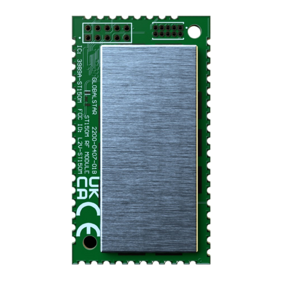
9150-0125-01 R-1 The ST150M weighs ~0.27oz (7.6g) with shield (no battery, no solar panel), with the dimensions shown below: 51mm FIGURE 1 - PHYSICAL DIMENSIONS 1.4. CERTIFICATIONS Globalstar products comply with WEEE and RoHS. The ST150M has the following certifications: •... -
Page 13: Application
2.1. THEORY OF OPERATION FOR GLOBALSTAR COMMERCIAL IOT The ST150M IoT Module operates on the Globalstar LEO satellite network. LEO (Low Earth Orbit) means that there are a number of satellites in low earth orbit that constantly orbit the planet and can communicate with Globalstar devices that are within range of its current position. -
Page 14: Quick Start/Configuration Guidelines
To get up and running, the following details both mandatory and optional steps: 1. Globalstar offers an ST150M Dev Kit that provides a quick way to power-up the module and communicate with modem AT command interface via physical UART, Globalstar Mobile App, or BLE Nordic UART Service (NUS) 2. -
Page 15: Core Components
1024 kB of flash and 256 kB of RAM located on the SoC. 2.4.5 ACCELEROMETER The ST150M contains a 3-axis accelerometer capable of 4098 LSB/g (// 16g), with scaling options of 2g, 4g, 8g and 16g, and high shock survivability of up to 10,000g. -
Page 16: Power Management
• Full Off: 2.7V • HW Protection Cutoff: 2.6V To set different thresholds via AT command details refer UAPI document Section 21.5 Voltage-Based Power Management and Section 21.6 State of Charge Power Management. ST150M User Manual Confidential & Proprietary Information... - Page 17 A variety of power notifications can be enabled including low voltage, Nordic MCU Temperature, transmitter temperature, battery pack temperature, and power state transitions. These settings and their thresholds can be enabled through the Config UAPI. For more details refer UAPI document section 21.15 POWER EVENT NOTIFY SETTINGS. ST150M User Manual Confidential & Proprietary Information...
-
Page 18: Peripherals
4. PERIPHERALS 4.1 NEAR-FIELD COMMUNICATION (NFC) There are two GPIO pins (P0.09/NFC1 and P0.10/NFC2) on the ST150M that can be configured to be a NFC listening device. The operating frequency is 13.56MHz and the bit rate is 106kbps. There are many NFC antennas on the market, but one that's been tested with the ST150M is Nordic Semiconductor's flex PCB NFC antenna. -
Page 19: Comparator
The pulse density modulation (PDM) module enables input of pulse density modulated signals from external audio frontends, for example, digital microphones. The PDM module generates the PDM clock and supports single-channel or dual-channel (Left and Right) data input. Data is transferred directly to RAM buffers using EasyDMA. ST150M User Manual Confidential & Proprietary Information... -
Page 20: Ppi - Programmable Peripheral Interconnect
QDEC phase input pins (A and B) at a fixed rate as specified in the SAMPLEPER register. If the SAMPLEPER value needs to be changed, the QDEC shall be stopped using the STOP task. ST150M User Manual Confidential & Proprietary Information... -
Page 21: Rtc - Real Time Counter
SPI master. The SPI master supports SPI modes 0 through 3. MODE CLOCK POLARITY CLOCK PHASE Mode 0(Leading) 0(Active High) SPI_MODE0 0(Leading) 1(Active Low) SPI_MODE2 1(Trailing) 0(Active High) SPI_MODE3 1(Trailing) 1(Active Low) ST150M User Manual Confidential & Proprietary Information... -
Page 22: Uart - Universal Asynchronous Receiver / Transmitter
If flow control is not enabled, the interface will behave as if the CTS and RTS lines are kept active all the time. UART pin Direction Output Value Input Input Output 1 Output 1 ST150M User Manual Confidential & Proprietary Information... -
Page 23: Using And Enabling Peripheral Devices
4.3 USING AND ENABLING PERIPHERAL DEVICES It is possible to re-assign the general purpose GPIO pins provided on the ST150M module to peripherals such as SPI ports and I2C ports using custom code. One existing I2C port is brought out to the external pins on the module and an I2C HAL is provided in the Globalstar SDK for sending data over that module. - Page 24 The Nordic nRF52840 can support up to 4 SPI master interfaces. At the Nordic SDK level, the SPI Master interfaces are identified via “instances” 1 – 4. The ST150M uses instance 1 to communicate with its on board GPS receiver. External devices cannot be added to this SPI port since its signals are dedicated to the GPS and are not brought out to external pins.
- Page 25 You will need to write a custom HAL for the SPI Slave device. • The HAL for the SPI Master device in the Globalstar ST150M SDK should be useful as a template for this • HAL. However, you will need to consult the Nordic SDK documentation as a reference how to link your new HAL into the SPI Slave control functions.
-
Page 26: Hardware Layout/Reference Design
3.3V level and programming GND10 Power Ground – SAT_DBG_ Serial wire debug clock input for Debug 3V level ASIC debug and programming Debug enable input for ASIC SAT_DBG_EN Debug 3V level debug and programming ST150M User Manual Confidential & Proprietary Information... - Page 27 3.3V level, Standard drive, low frequency I/O only P1.01 Digital I/O GPIO 3.3V level, Standard drive, low frequency I/O only P0.24 Digital I/O GPIO 3.3V level GND7 Power Ground – P0.25 Digital I/O GPIO 3.3V level ST150M User Manual Confidential & Proprietary Information...
- Page 28 Control signal for external GPS Digital Output 3.3V level LNA_EN Signal for indicating ASIC trans- VRF_EN Digital Output 3V level mission I2C_SDA Digital I/O I2C serial data 3.3V level I2C_CLK Digital Output I2C serial clock 3.3V level ST150M User Manual Confidential & Proprietary Information...
-
Page 29: Reference Circuitry
1. The antenna used must be a patch antenna. 2. The antenna peak gain must not exceed 5.1dB. 3. The antenna must be passively connected to the RF output of the ST150M using a 50-ohm nominal impedance printed circuit trace. No connectors are allowed on the antenna connection. -
Page 30: Pcb Layout Example
5.2.3 PCB LAYOUT EXAMPLE FIGURE 7 – TOP AND BOTTOM LAYOUTS FIGURE 9 – BLE LAYOUT FIGURE 10 – GPS LAYOUT FIGURE 8 – STX LAYOUT FIGURE 11 – TOP AND BOTTOM PCB VIEWS ST150M User Manual Confidential & Proprietary Information... -
Page 31: Figure 12 - Stx, Ble, And Gps Views (Left To Right)
9150-0125-01 R-1 FIGURE 12 – STX, BLE, AND GPS VIEWS (LEFT TO RIGHT) ST150M User Manual Confidential & Proprietary Information... -
Page 32: Reference Design Schematics
9150-0125-01 R-1 5.3 REFERENCE DESIGN SCHEMATICS ST150M User Manual Confidential & Proprietary Information... -
Page 33: Transmit/Receive Antenna Requirements
PCB to the approved antennas (referenced above). No antenna connector or any other antenna may be used. In order for any device to obtain certification from Globalstar for use under this modular approval, this condition must be met. -
Page 34: Trace And Cable Losses
50 Ohm impedance trace on the circuit board. The following example impedance calculation is for a co-planar waveguide trace on the top layer of a standard 0.063” FR-4 2-layer board material (60-mil core material) with a dielectric εr ≈ 4.6 and 1/2 oz. Copper. FIGURE 13 - COPLANAR WAVEGUIDE ST150M User Manual Confidential & Proprietary Information... -
Page 35: Recommended Operating Conditions
1. Use a grounding bracelet if possible, to minimize charge build-up on personnel. It is strongly advised to not leave unused Nordic pins at high 2. Handle the ST150M PCB by the edges without touching impedance (input without internal pulldown). components or printed circuit paths. -
Page 36: Application Programming Interface (Api)
This interface requires usage of a 128bit shared AES key to encrypt/decrypt BLE traffic. Only the device owner can access the shared key, either via the Device Management APIs or using the Globalstar mobile application. Specific details of the ST150 Configuration Service Implementation can be found in the document: 8550-0009-01 R-1 Globalstar IOT Configuration BLE Service Specification •... -
Page 37: General Configuration
5. Track events 6. GPS module 7. Accelerometer 8. Power Management 9. Logging component 10. OTA Events App URCs for supported component events can be enabled for visibility from external interfaces using following AT commands. ST150M User Manual Confidential & Proprietary Information... -
Page 38: Transmitter Event Notification Settings
To receive all Transmitter event notifications, the valid command to activate all notifications AT+TXNSF = 2047. • AT+TXNSF = 2048 will return ERROR. 7.3 MESSAGE QUEUE EVENT NOTIFICATION SETTINGS Supported Transmitter Event notifications code <messageQueueNotifyFlags> ST150M User Manual Confidential & Proprietary Information... -
Page 39: Set Message Queue Notify Flags Via Nus, Uart
7.4.1 SET GPIO NOTIFY FLAGS VIA NUS, UART AT+GPIONSF = <GPIONotifyFlags> 7.4.2 READ GPIO NOTIFY FLAGS VIA NUS, UART AT+GPIONSF? Response + GPIONSF: <GPIONotifyFlags> 7.4.3 SET GPIO NOTIFY FLAGS VIA CONFIGURATION SERVICE AT+GPIOANSF = <GPIONotifyFlags> ST150M User Manual Confidential & Proprietary Information... -
Page 40: Read Gpio Notify Flags Via Configuration Service
To receive all Inputs/Count event notifications over configuration service, the valid command to activate all notifications AT+CAPPNSF = 2047. • AT+CNSF = 2048 will return ERROR. • Configuring any reserved notification will return error. ST150M User Manual Confidential & Proprietary Information... -
Page 41: Inputs/Count Event Notification Settings
Configuring any reserved notification will return error. 7.6 TRACK EVENTS NOTIFICATION SETTINGS Supported Track Event notifications code <TrackNotifyFlags> • TRACK_NOTIFY_FLAGS_UPDATE_TRIGGERED = 1 • TRACK_NOTIFY_FLAGS_RESERVED_1 = 2 • TRACK_NOTIFY_FLAGS_RESERVED_2 = 4 • TRACK_NOTIFY_FLAGS_RESERVED_3 = 8 • TRACK_NOTIFY_FLAGS_LOCATION_ERROR = 16 ST150M User Manual Confidential & Proprietary Information... -
Page 42: Set Track Events Notify Flags Via Nus, Uart
OTA_EVENT_NOTIFY_FLAGS_ACCUMULATED_ROLLOVER = 1024 7.7.1 SET OTA EVENTS NOTIFY FLAGS VIA NUS, UART. AT+CANSF = < OTAEventNotifyFlags > 7.7.2 READ OTA EVENTS NOTIFY FLAGS VIA NUS, UART. AT+CANSF? Response + CANSF: < OTAEventNotifyFlags > ST150M User Manual Confidential & Proprietary Information... -
Page 43: Set Ota Events Notify Flags Via Configuration Service
7.8.1 SET GPS NOTIFY FLAGS VIA NUS, UART. AT+GNSF = < GPSNotifyFlags> 7.8.2 READ GPS NOTIFY FLAGS VIA NUS, UART. AT+GNSF? Response + GNSF: < GPSNotifyFlags> 7.8.3 SET GPS NOTIFY FLAGS VIA CONFIGURATION SERVICE AT+GANSF = < GPSNotifyFlags> ST150M User Manual Confidential & Proprietary Information... -
Page 44: Read Gps Notify Flags Via Configuration Service
7.9.4 READ ACCELEROMETER EVENT NOTIFY FLAGS VIA CONFIGURATION SERVICE AT+AANSF? Response + ANSF: <AccelerometerNotifyFlags> Example: • To receive accelerometer vibration triggered and in motion event notification, the valid command to activate notification AT+ANSF = 68. ST150M User Manual Confidential & Proprietary Information... -
Page 45: Power Management Event Notification Settings
To receive all Power Management event notifications, the valid command to activate all notifications AT+PNSF = 127. • To receive all Power Management notifications over configuration service, the valid command to activate all notifications AT+PANSF = 127. • AT+PNSF = 128 will return ERROR. ST150M User Manual Confidential & Proprietary Information... -
Page 46: External Flash Logging Event Notification Settings
The meaning of the single argument is “GPIO type” where 0 = All, 1 = Available, 2 = Reserved. The response format is as follows: +GPIOLIST:<key>,<property>,<pin>,<is enabled>,<is fixed>,<type>,<set state>,<read state>,<is active high>,<ISR received>,<description> ST150M User Manual Confidential & Proprietary Information... -
Page 47: Configuring Inputs
+GPIOLIST:17,0,39,0,1,0,0,0,0,0,P1.07 +GPIOLIST:18,0,42,0,1,0,0,0,0,0,P1.10 +GPIOLIST:19,0,44,0,1,0,0,0,0,0,P1.12 +GPIOLIST:20,0,46,0,1,0,0,0,0,0,P1.14 +GPIOLIST:21,0,47,0,1,0,0,0,0,0,P1.15 +GPIOLIST:22,2,0,0,0,0,0,0,0,0,Tamper +GPIOLIST:23,3,0,0,0,0,0,0,0,0,Line Pwr +GPIOLIST:24,4,0,0,0,0,0,0,0,0,Adv Enable 7.12.2 CONFIGURING INPUTS: To reserve one of the inputs in the list above, use: AT+GPIOCFGIN=<reserved>,<key>,[<is_active_high>] Examples: Reserve key 0 as active high AT+GPIOCFGIN=1,0,1 ST150M User Manual Confidential & Proprietary Information... -
Page 48: Mapping Inputs
Map actual pin 3 to input 2 in OTA messages: AT+INMAP=3,2 “AT+INMAP?” Returns the mapped inputs. For example, issuing this query after doing the mappings listed above results in: AT+INMAP? +INMAP: 3,2 +INMAP: 48,1 OK ST150M User Manual Confidential & Proprietary Information... -
Page 49: Getting The Input State Of Mapped Inputs
In one of the examples above, we reserved the pin who’s key is “0”, and the Nordic pin number is “2”. When this pin transitions from low to high, the URC generated will be: +URC: “GPIO”,17,1,0,2,1 ST150M User Manual Confidential & Proprietary Information... -
Page 50: Enabling And Configuring The Uart
Use “AT+UART2PROP?” To query the configuration. Here is a query showing the factory default configuration for the ST150 Module. Note that the UART is enabled by default. Default baud rate is 9600 baud. AT+UART2PROP? +UART2PROP:1,6,4,3 ST150M User Manual Confidential & Proprietary Information... -
Page 51: Software High Level Overview
8.1 BLE CONFIGURATION SERVICE AND INTERFACES BLE Configuration Service is an encrypted BLE service used by the Globalstar Mobile App to provide trusted user authentication and access to all device configuration settings. It is necessary to first create a user account, as outlined in the Quick Start section, in order to securely access the device settings. -
Page 52: Temporarily Enabled With Timeout
Additionally, elevated authorization status will timeout automatically after a pre-set configurable time. The auth command enables write-access, however, is not saved to persistent storage and will reset when the device resets or when an auth disable command is executed. ST150M User Manual Confidential & Proprietary Information... -
Page 53: Unified Api Modules
9. UNIFIED API MODULES The Unified API is Globalstar’s SDK that incorporates the same API command whether used externally over UART, or through source code directly. All AT commands rely on documented C APIs that are available to system integrators writing custom firmware applications. -
Page 54: Messages
UAPI module events and sequences of events into OTA messages. Legacy messages are intended for backwards compatibility with previous Globalstar products. Modular messages allow for future scalability and payload customization by use of a configuration byte for each modular message profile. For example, a Device Reset event can send a Modular Turned On Message that includes UTC time from the Modular Message UTC Time profile and custom raw payload. - Page 55 9.1.5.2 Channel Selection The transmitter is required to switch channels depending on its global location. The ST150M can automatically channelsteer the ASIC when a GPS position is obtained or input, or the user can manually set the operating channel.
- Page 56 9.1.8.1 Tamper Detection Used to trigger a tamper event 9.1.8.2 Line Power Detection Used for line-power detection status. Line Power status is described in the monthly Health Check OTA message, but can also ST150M User Manual Confidential & Proprietary Information...
- Page 57 9.1.8.3 Advertising Enable Used to re-enable BLE Configuration Service advertising temporarily if it has been disabled. This makes it possible to reconnect the Globalstar Mobile App if the BLE Configuration Service is normally disabled. 9.1.8.4 Fixed and Non-Fixed Special Functions Special functions can be assigned to un-reserved pins if the special function entry is not fixed.
- Page 58 The GPS fix timeout refers to the maximum amount of time the GPS module will wait to obtain a position before giving up and putting the GPS back into a low-power state. 9.1.15.3 Fix Settle Time ST150M User Manual Confidential & Proprietary Information...
-
Page 59: Power Settings
The RTC time may drift over time, and thus, an adjustable stale time setting will cause the RTC Module to request a GPS fix. 9.1.15.13 Set RTC Time A set RTC time API is available. Additionally, the RTC will be synchronized to UTC time if the set GPS Position API is used (see GPS Module Section). ST150M User Manual Confidential & Proprietary Information... -
Page 60: Accelerometer Module
In the Partial Suspended state, tracking occurs at the low battery update interval, if the low battery update interval is less than the normal or in-motion interval respective of the current tracking state. ST150M User Manual Confidential & Proprietary Information... -
Page 61: Full Suspended
9.1.17.4 Power Management State Changes Power management state changes can be set with the Power Management Set Power State API. Based on the user’s implementation and power architecture, the ST150M’s power state can be directed to the appropriate state. 9.1.18 Temperature Notifications Temperature notification events can be configured for high/low temperatures on the ASIC and MCU. -
Page 62: Smart One Sensor Service Settings
9.1.20.6 Smart One Sensor Service Settings Smart One Sensor Service is a BLE service the ST150M offers where up to 10 sensor nodes may advertise data to be sent over-the-air when data is available and needs to send. The ST150M will switch from peripheral mode to central mode at the Sensor Service Scan Interval below, and look for any advertising sensor nodes. -
Page 63: Test Modes
The Modulation Test Mode command requests the device to enter the Modulation test mode. This will cause the device to output back-to-back test packets continuously for 30 seconds after which it will turn off the RF output and return to sleep mode. ST150M User Manual Confidential & Proprietary Information... -
Page 64: Ordering Information/Device Markings/Activation Information
2. Hardware SKU – Used by Globalstar to identify different base hardware configurations 3. Product SKU – Used by Globalstar to identify different products using a specific Hardware SKU as the base module 4. Globalstar Part Number 5. Scannable DataMatrix Code – Contains product information in the format <UID>,<Hardware SKU ID>,<Hardware SKU Sring ID>,<Product SKU ID>,<Product SKU String ID>,<Globalstar Part Number>... -
Page 65: How To Order
11.4 GLOBALSTAR PRODUCT CERTIFICATION Before a customer’s end product can be used on the Globalstar network, it must receive a Globalstar Product Certification. The certification process ensures that the customer’s product meets Globalstar’s internal system standards and has received the applicable regulatory approvals for the countries it will be operating in. -
Page 66: General Warnings
ST100 and a pacemaker to avoid potential interference with the pacemaker. Warning – Hearing Aids: Some digital wireless devices may interfere with some hearing aids. In order to prevent such interference, you may want to consult the manufacturer of your hearing aid. ST150M User Manual Confidential & Proprietary Information... -
Page 67: Regulatory
C4PC for ISED). The ST150M BOARD module has been labeled with its own FCC and Industry Canada (IC) ID numbers, and if the FCC/IC ID numbers are not visible when the module is installed inside another device, then the outside of the finished product into which... - Page 68 Cet appareil numérique de classe B est conforme à la norme NMB-003. Hereby, Globalstar declares that this ST150M is in compliance with the essential requirements and other relevant provisions of Directive 2014/53/EU. The declaration of conformity may be consulted at www.
- Page 69 FOR HOME OR OFFICE USE The ST150M has been so constructed that the product complies with the requirement of Article 10(2) as it can be operated in at least one Member State as examined and the product is compliant with Article 10(10) as it has no restrictions on being put into service in all of the EU except Ireland.
-
Page 70: Acronym List
Global Positioning System HTTP Hypertext Transfer Protocol Hardware Inter-Integrated Circuit Industry Canada iPhone Operating System ISED Innovation, Science and Economic Development (Canada) JTAG Joint Test Action Group Low Earth Orbiting Milliamps Milliamp Hour ST150M User Manual Confidential & Proprietary Information... - Page 71 Software Development Kit Sub-Miniature Version A Satellite Transmitter Unit Transmit UART Universal Asynchronous Receiver/Transmitter Volts Value Added Manufacturer Value Added Reseller Voltage Direct Current Vector Network Analyzer WEEE Waste Electrical & Electronic Equipment (Europe) ST150M User Manual Confidential & Proprietary Information...
- Page 72 9150-0125-01 R-1 ST150M User Manual Confidential & Proprietary Information 9150-0125-01 R-1...