
Related Manuals for Globalstar STINGR


Summary of Contents for Globalstar STINGR
- Page 1 Revision 0.2 STINGR Users Manual STINGR Users Manual Revision 0.2 Subject To Change without Notice P a g e 06/24/15...
-
Page 2: Table Of Contents
Setup (0x06) .............................. 19 5.2.2.7 Query Setup (0x07) ........................... 20 5.2.2.8 Query Hardware Version (0x09) ....................... 21 5.2.3 STINGR Serial Packet Commands ........................22 5.2.3.1 “Initiate proprietary track” command ...................... 22 5.2.3.2 “Update Proprietary Track Data” command ..................... 23 5.2.3.3 “Cancel Proprietary Track”... - Page 3 Revision 0.2 STINGR Users Manual “Transmitter Test” command ..........................27 Example CRC calculation routines for serial packets .................... 29 Test Modes ..................................31 REGULATORY APPROVAL .............................. 33 Radio Astronomy Site Avoidance .......................... 33 Regulatory Notices ..............................33 Revision 0.2 Subject To Change without Notice...
-
Page 4: Introduction
The STINGR is a satellite transmitter radio module which contains a satellite transmitter, GPS receiver, motion sensor, and a dual band patch antenna. The STINGR is a surface mount module designed to attach to a user defined host PCB which must provide power and communications with a host processor which will control the operation of the STINGR. -
Page 5: Application
2.1 Theory of Operation The STINGR operates on the Globalstar LEO satellite network. LEO (Low Earth Orbit) means that there are a number of operates on the Globalstar LEO satellite network. LEO (Low Earth Orbit) means that there are a number of operates on the Globalstar LEO satellite network. - Page 6 (redundant) transmissions for each message being sent over the Globalstar network. The default value for the number of redundant sent over the Globalstar network. The default value for the number of redundant transmissions transmissions per message is 3. This means that each message sent to the STINGR STINGR will be transmitted 3 times.
- Page 7 Revision 0.2 Revision 0.2 STINGR Users Manual The transmission sequence for a two-packet message using the default setting of 3 redundant transmissions is shown packet message using the default setting of 3 redundant transmissions is shown packet message using the default setting of 3 redundant transmissions is shown below.
-
Page 8: Block Diagram
(PWR_EN) is provided by the to the random nature of the burst transmissions, and open collector output (PWR_EN) is provided by the STINGR which can directly control an external high current supply for... -
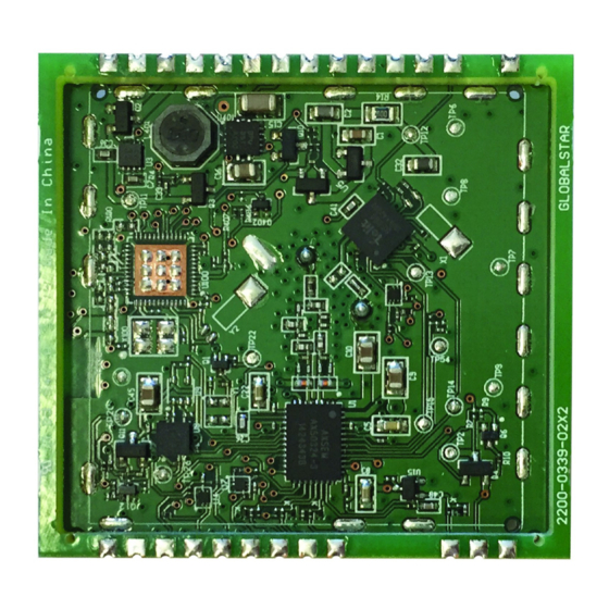
Page 9: Physical Charactersistics
Revision 0.2 STINGR Users Manual 3 Physical Charactersistics Figure 5 Top View Revision 0.2 Subject To Change without Notice P a g e 06/24/15... - Page 10 Revision 0.2 STINGR Users Manual Figure 6 Recommended PCB footprint layout Revision 0.2 Subject To Change without Notice P a g e | 10 06/24/15...
- Page 11 Sleep Mode VBATT is applied, no transmissions are pending, no serial activity Active Mode The STINGR is active and responding to the serial port but is not transmitting Standby Mode The STINGR is inactive between transmissions but is not transmitting Revision 0.2...
- Page 12 Revision 0.2 STINGR Users Manual Transmit Mode The unit is transmitting an RF packet Parameter Test Conditions Unit Transmit mode supply current -40-85º C, VBATT=3.7 volts Active mode supply current 25º C, VBATT = 3.7 volts Standby mode supply current 25º...
-
Page 13: Reference Design
USB interface, and test mode switches. Since the battery is located on the same board as the STINGR, no decoupling capacitor is required on the VBATT input, however, if there are battery leads, lengthy power distribution, or noise sources present, a suitable decoupling capacitor might be appropriate. -
Page 14: Schematic
Revision 0.2 STINGR Users Manual 4.1 Schematic Revision 0.2 Subject To Change without Notice P a g e | 14 06/24/15... -
Page 15: Pcb
Revision 0.2 STINGR Users Manual 4.2 PCB 4.3 BOM Manufacturer Part Number Designator Description Manufacturer Quantity BC2/3AE Multicell Battery GRM155R71A104KA01D C1, C3 CAP 0402 CER 100NF 10V X7R +/-10% MURATAELEC 04026D105KAT2A CAP 0402 CER 100NF 10V X7R +/-10% AVXCORP SP0503BAHTG... -
Page 16: Application Programming Interface
DTE and, if applicable, executes the command. In order to wake the STINGR from sleep mode and to indicate the end of the serial packet, each serial packet must be framed by activating RTS before the first byte of the command and deactivating RTS after the last byte of the command. -
Page 17: Serial Packet Format
Globalstar Simplex network. he Globalstar Simplex network. If the STINGR receives a properly formatted Send Data command, it returns an acknowledge response as shown above. If receives a properly formatted Send Data command, it returns an acknowledge response as shown above. If receives a properly formatted Send Data command, it returns an acknowledge response as shown above. -
Page 18: Query Electronic Serial Number (Esn) (0X01)
Revision 0.2 STINGR Users Manual 5.2.2.2 Query Electronic Serial Number (ESN) (0x01) The Electronic Serial Number command requests the STINGR to respond with the units Electronic Serial Number (ESN). 0x01 Leader CRC1 CRC2 Command: AA 05 01 50 D5 Response:... -
Page 19: Query Firmware Version (0X05)
AA 07 05 01 07 E0 6A Where the firmware version returned is: 5.2.2.6 Setup (0x06) The Setup command requests the STINGR to use the specified current setup parameters. These are stored in non- volatile memory. 0x06 Command: header len 04... -
Page 20: Query Setup (0X07)
0x18 = 24, 24 x 5 = 120 seconds • Maximum Burst Interval: 0x30 = 48, 48 x 5 = 240 seconds • 5.2.2.7 Query Setup (0x07) The Query Setup command requests the STINGR to return the current setup parameters. 0x07 Leader CRC1 CRC2 Command:... -
Page 21: Query Hardware Version (0X09)
0x18 = 24, 24 x 5 = 120 seconds • Maximum Burst Interval: 0x30 = 48, 48 x 5 = 240 seconds • 5.2.2.8 Query Hardware Version (0x09) The Query Hardware Version command requests the STINGR to return the current hardware version information. 0x09 Leader CRC1 CRC2 Command:... -
Page 22: Stingr Serial Packet Commands
Revision 0.2 STINGR Users Manual 5.2.3 STINGR Serial Packet Commands 5.2.3.1 “Initiate proprietary track” command This command allows the initiation of a periodic track with user defined data prepended and appended to the latitude and longitude fields. A periodic 9 byte custom track message, transmitted nominally at the interval specified, will result. -
Page 23: Update Proprietary Track Data" Command
Revision 0.2 STINGR Users Manual Initiate proprietary track response Byte Bits Parameter Description 0 - 7 Leader Always a value of 0xAA. 0 - 7 Length 0 - 7 Command Code. 0x30 = ACK or 0xFF = NAK 3 -4... -
Page 24: Cancel Proprietary Track" Command
Revision 0.2 STINGR Users Manual Where: Payload Byte 0: 0xAA • Payload Byte 7: 0xBB • Payload Byte 8: 0xCC • Update Proprietary Track Data response Byte Bits Parameter Description 0 - 7 Leader Always a value of 0xAA. 0 - 7... -
Page 25: Send Redundant Burst With Gps" Command
This command is used to initiate a redundant bursted message (as setup in STX configuration). Bytes 1 – 6 of the first packet of the message shall contain latitude and longitude in standard Globalstar 24 bit format. Send Redundant Burst with GPS command format... - Page 26 Revision 0.2 STINGR Users Manual Leader Byte 0 Byte 7 Byte 8 CRC1 CRC2 Example Command: AA 08 33 AA BB CC 57 C3 Where: Payload Byte 0: 0xAA • Payload Byte 7: 0xBB • Payload Byte 8: 0xCC •...
-
Page 27: Stingr Serial Test Commands
Revision 0.2 STINGR Users Manual 5.2.4 STINGR Serial Test Commands 5.3 “Transmitter Test” command This command is used to initiate a transmitter test in one of three modes. Transmitter test command format Byte Bits Parameter Description 0 - 7 Leader Always a value of 0xAA. - Page 28 Revision 0.2 STINGR Users Manual Table 50: Transmitter test response format. Byte Bits Parameter Description 0 - 7 Leader Always a value of 0xAA. 0 - 7 Length 0x05 0xFC for success, 0xFF for incorrectly 0 - 7 ACK or NAK formatted command.
-
Page 29: Example Crc Calculation Routines For Serial Packets
Revision 0.2 STINGR Users Manual 5.4 Example CRC calculation routines for serial packets The following example is written in the C programming language where: int = 32 bits, short = 16 bits, char = 8 bits unsigned short crc16_lsb(unsigned char *pData, int length) unsigned char i;... - Page 30 Revision 0.2 STINGR Users Manual The following example is written in the Java programming language: char crc16_lsb(byte pData[], int length) int pData_i = 0; char s1,s2; byte i; char data, crc; crc = (char) 0xFFFF; if (length == 0) return 0;...
-
Page 31: Test Modes
All test modes are activated by grounding selective pins on the STINGR prior to applying power. Once power is applied, the STINGR will sample the states of the pins and based on the states of the pins, the STINGR will enter the selected test mode. - Page 32 Revision 0.2 STINGR Users Manual The channels are selected via the Rx and RTS pins as follows Channel Channel specified in the flash setup. To specify channel A, it must be the default channel specified in the flash setup. See Setup command for details.
-
Page 33: Regulatory Approval
The STINGR module has been labeled with its own FCC and Industry Canada (IC) ID numbers, and if the FCC/IC ID numbers are not visible when the module is installed inside another device, then the outside of the finished product into... - Page 34 • Consult the dealer or an experienced radio/TV technician for help. WARNING: Changes or modifications not expressly approved by Globalstar may render the device non-compliant to FCC and other regulatory body standards for operation and may void the user’s authority to operate the equipment.
- Page 35 Revision 0.2 STINGR Users Manual FCC ID: L2V-STGR ICES-003/(A/B) IC:3989A-STGR R&TTE: TBR41 Complies with FCC standards. FOR HOME OR OFFICE USE Revision 0.2 Subject To Change without Notice P a g e | 35 06/24/15...
Need help?
Do you have a question about the STINGR and is the answer not in the manual?
Questions and answers