Honeywell NOTIFIER NCA-2 Instruction Manual
Network control annunciator
Hide thumbs
Also See for NOTIFIER NCA-2:
- Product installation document (18 pages) ,
- Wiring manual (80 pages) ,
- Programming and operations manual (46 pages)

Related Manuals for Honeywell NOTIFIER NCA-2


Summary of Contents for Honeywell NOTIFIER NCA-2
- Page 1 Network Control Annunciator NCA-2 Instruction Manual Document 52482 Rev: M5 03/20/2019 ECN: 18-0305...
- Page 2 Fire Alarm & Emergency Communication System Limitations While a life safety system may lower insurance rates, it is not a substitute for life and property insurance! An automatic fire alarm system—typically made up of smoke Heat detectors do not sense particles of combustion and alarm detectors, heat detectors, manual pull stations, audible warning only when heat on their sensors increases at a predetermined rate devices, and a fire alarm control panel (FACP) with remote notifica-...
- Page 3 Microsoft® and Windows® are registered trademarks of the Microsoft Corporation. Chrome™ and Google™ are trademarks of Google Inc. ©Wednesday, March 20, 2019 by Honeywell International Inc. All rights reserved. Unauthorized use of this document is strictly prohibited. NCA-2 Manual — P/N 52482:M5 03/20/2019...
- Page 4 Brief description of content you think should be improved or corrected • Your suggestion for how to correct/improve documentation Send email messages to: FireSystems.TechPubs@honeywell.com Please note this email address is for documentation feedback only. If you have any technical issues, please contact Technical Services. NCA-2 Manual — P/N 52482:M5 03/20/2019...
-
Page 5: Table Of Contents
Table of Contents Section 1: About this Manual ............................8 1.1: Standards and Specifications .....................................8 1.2: UL 864 Compliance......................................8 1.2.1: UL 864 9th and 10th Edition ..................................8 1.3: Programming Features Subject to AHJ Approval..............................8 1.4: Related Documentation ....................................10 1.5: Notes, Cautions, and Warnings..................................11 1.6: Conventions ........................................11 Section 2: Overview ................................ - Page 6 Table of Contents 4.2.2: Event Counts Display ...................................39 4.2.3: Multiple Event List ....................................40 4.2.4: Local and Node History Display ................................41 4.2.5: Read Status ......................................45 4.2.6: Program/Alter Status ....................................48 4.2.7: Printer Functions....................................48 4.3: Events ..........................................52 4.3.1: About Events ......................................52 4.3.2: Types of Events ....................................52 4.3.3: Event Handling .....................................52 Section 5: Programming ..............................
- Page 7 Table of Contents 4.: Alarm Reset ......................................105 4.: Trouble Condition....................................105 Section 2: NCA-2 Key Functions ..................................105 Section 2: Acknowledge ....................................105 Section 2: Signal Silence ....................................105 2.: Drill/Alarm Signal (Canada)..................................105 2.: System Reset......................................105 2.: Lamp Test ........................................105 Section 3: LED Indicators.....................................105 Section 3: Power ......................................105 Section 3: Fire Alarm....................................105 Section 3: Pre-Alarm ....................................105...
-
Page 8: Section 1: About This Manual
Section 1: About this Manual 1.1 Standards and Specifications The NCA-2 has been designed to comply with standards set forth by the following regulatory agencies: • Underwriters Laboratories Standard UL 864 • Underwriters Laboratories Standard UL 2017 for General-Purpose Signaling Devices and Systems •... - Page 9 Programming Features Subject to AHJ Approval About this Manual This product incorporates field-programmable software. In order for the product to comply with the requirements in the Standard for Control Units and Accessories for Fire Alarm Systems, UL 864/ULC-S527, certain programming features or options must be limited to specific values or not used at all as indicated below.
-
Page 10: Related Documentation
About this Manual Related Documentation 1.4 Related Documentation The table below provides a list of documents referenced in this manual, as well as documents for selected other compatible devices. Compatible Conventional Devices (Non-addressable) Document Number Device Compatibility Document 15378 Off-line Programming Utility Document Number VeriFire™... -
Page 11: Notes, Cautions, And Warnings
Notes, Cautions, and Warnings About this Manual SCS Smoke Control (Smoke and HVAC Control Station) Manual 15712 TM-4 Installation Document (Reverse Polarity Transmitter) 51490 UDACT Manual (Universal Digital Alarm Communicator/Transmitter) 50050 UDACT-2 (Universal Digital Alarm Communicator/Transmitter) Listing Document 54089LD UZC-256 Universal Zone Coder Manual 15216 UZC-256 Programming Manual 15976... -
Page 12: Section 2: Overview
Section 2: Overview 2.1 General Description The NCA-2 Network Control Annunciator provides a text-based display and control device for a NOTI•FIRE•NET™ or High-Speed NOTI•FIRE•NET™ system. The NCA-2 uses a 640-character LCD (16 x 40), a high-speed 32-bit microprocessor, flash memory and a rubberized QWERTY keypad. -
Page 13: 2: Compatibility With Noti•Fire•Net™ Panel Nodes
General Description Overview - Power - Fire Alarm - Pre-Alarm - Security - Supervisory - System Trouble - Other Event - Signals Silenced - Point Disabled - CPU Failure - Controls Active • Support for a custom “system-normal” bitmap graphic •... -
Page 14: Nca-2 And Displayless Panels
Overview NCA-2 and Displayless Panels 2.2 NCA-2 and Displayless Panels When there is a displayless NFS2-640 or NFS2-3030 on a Noti•Fire•Net™, the NCA-2 acts as a remote display. Displayless Panel Noti•Fire•Net™ or High-Speed Noti•Fire•Net™ NCM-W shown NCA-2 NCM-W shown Figure 2.3 NCA-2 and Displayless Panels 2.3 NCA-2 / NFS2-640 Standalone Application The NCA-2 can mount in a chassis in the same cabinet as the NFS2-640 panel and connect directly to it via the NUP ports using the NUP cable (P/N 75577);... - Page 15 NCA-2 / NFS2-640 Standalone Application Overview NFS2-640 in chassis Connection NCA-2 in chassis Figure 2.4 The NCA-2 as the NFS2-640 Display NOTE: This system design is required for Canadian standalone applications. NCA-2 Manual — P/N 52482:M5 03/20/2019...
-
Page 16: Nca-2 Board Layout
Overview NCA-2 Board Layout 2.4 NCA-2 Board Layout Figure 2.5 shows NCA-2 circuit board layout; descriptions of the components follow in the next sections. USB VeriFire Tools connection TB7 ACS (power-limited/Class 2, supervised) Note: Relay circuits are power-limited (Class 2) only if connected to a power-limited signal source. -
Page 17: Nca-2 Keypad Layout
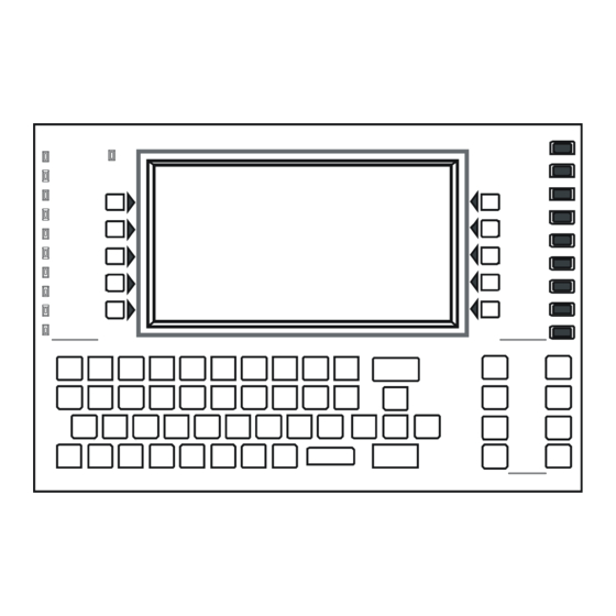
NCA-2 Keypad Layout Overview 2.5 NCA-2 Keypad Layout The keyboard figure below illustrates the basic layout. The keypad is described in detail in the operation section of this manual, in “The Keypad” on page 36. Soft Keys Status Multi-line Fixed Function LEDs LCD Screen Keys... -
Page 18: 4: Other Optional Devices
Overview NCA-2 Components LDM-32 and LDM-R32. The Lamp Driver Annunciator Module-32 provides 32 alarms or 16 alarm and 16 trouble lamp driver outputs, corresponding to 32 annunciator points that can be connected to external devices like custom graphic annunciators. The Lamp Driver Annunciator Module expander module expands the LDM-32 by 32 annunciator points, for a maximum of 64 points. -
Page 19: Section 3: Installation
Section 3: Installation 3.1 Preparing for Installation Choose a location for the NCA-2 that is clean, dry, and vibration-free with moderate temperature. The area should be readily accessible with sufficient room to easily install and maintain it. There should be sufficient space for cabinet door(s) to open completely. Carefully unpack the system and inspect for shipping damage. -
Page 20: Cab-4 Series Cabinet
Installation CAB-4 Series Cabinet 3.3 CAB-4 Series Cabinet This section provides instructions for mounting the CAB-4 Series backbox to a wall. Follow these guidelines when mounting the back- box: Locate the cabinet backbox on a surface that is in a clean, dry, vibration-free area. The top should be located so that all operational but- tons, switches, displays, etc. -
Page 21: Abs-2D, Abs-4D Cabinets
ABS-2D, ABS-4D Cabinets Installation 3.4 ABS-2D, ABS-4D Cabinets ABS-2D To mount an NCA-2 in an ABS-2D cabinet, follow the directions in the illustration below. 1. Secure the ABS-2D 3. Install four .75 in. ABS-2D to the #4-40 female CHS-2D wall using the two aluminum standoffs keyholes on its (included, p/n 42042) -
Page 22: Chs-M3 Chassis
Installation CHS-M3 Chassis 3.5 CHS-M3 Chassis 3.5.1 Layout The NCA-2 mounts in chassis CHS-M3 in the top row of the cabinet. Four positions The NCA-2 occupies the left half of the chassis (positions 1 and 2, see on chassis Figure 3.3). CHS-M3 Positions 3 and 4 of CHS-M3 can hold up to four layers of equipment including annunciators and option boards. -
Page 23: 3: Memory-Backup Battery
CHS-M3 Chassis Installation 1-15/16” (4.92 cm) aluminum male/female 4-40 standoffs at positions indicated Chassis-mounting slots NCA-2 mounting slots Figure 3.5 Standoffs on Chassis CHS-M3 CAUTION: MOUNTING CONSIDERATIONS IT IS CRITICAL THAT ALL MOUNTING HOLES OF THE NCA-2 ARE SECURED WITH A SCREW OR STAND-OFF TO INSURE CONTINUITY OF EARTH GROUND. -
Page 24: 4: Option Boards
Installation CA-2 Chassis Assembly 3.5.4 Option Boards If installing option boards on the CHS-M3, connect Attach stand-offs for them at this time. As described in Section 3.5.1 “Lay- option boards here..and here out”, up to eight option boards can be mounted in CHS- M3 to the right of the NCA-2. - Page 25 CA-2 Chassis Assembly Installation CA-2 half-chassis for NCA-2 NCA-2 Fasten with four 4-40 screws (P/N 38134, Slide the tabs at the bottom of included with NCA-2) as indicated. the NCA-2 into the outer slots at the bottom of the chassis. Figure 3.8 Mounting the NCA-2 onto the CA-2 Half-chassis Refer to the DVC Manual and CA-2 product installation document for installation of the DVC-EM, microphone and handset into the CA-2.
-
Page 26: Nca-2 / Nfs2-640 Standalone
Installation NCA-2 / NFS2-640 Standalone 3.7 NCA-2 / NFS2-640 Standalone The NCA-2 may be mounted over a displayless NFS2-640 using the hardware from attachment kit p/n NCA/640-2-KIT. Refer to Figure 3.9. Attach annunciator to panel with standoffs and screws from STEP 5 the attachment kit. -
Page 27: Network Communications Module
Network Communications Module Installation SW1 set to Security SW2 set to Supervisory Move switch to opposite position to convert to Alarm relays. Figure 3.10 Form-C Relay Connections 3.10 Network Communications Module Standard Network Communications Module, NCM-W/F If networking two or more control panels on a standard NOTI•FIRE•NET™ (including NCA-2s): •... -
Page 28: Central Station Fire Alarm System Canadian Requirements
Installation Central Station Fire Alarm System Canadian Requirements 3.11 Central Station Fire Alarm System Canadian Requirements For Canadian applications requiring a second dial-out option, refer to the following illustration for UDACT/UDACT-2 and TM-4 setup: MR-101/C and FMM-1 Wiring on Networked FACP 18/24 MR-101/C FMM-1... -
Page 29: Connecting Power Sources And Outputs
Connecting Power Sources and Outputs Installation 3.12 Connecting Power Sources and Outputs WARNING: REMOVE POWER SOURCES WHILE CONNECTING COMPONENTS REMOVE ALL POWER SOURCES TO EQUIPMENT WHILE CONNECTING ELECTRICAL COMPONENTS. LEAVE THE EXTERNAL, MAIN POWER BREAKER OFF UNTIL INSTALLATION OF THE ENTIRE SYSTEM IS COMPLETE. WARNING: REMOVE ALL SOURCES OF POWER BEFORE SERVICE SEVERAL SOURCES OF POWER CAN BE CONNECTED TO THE CONTROL PANEL. -
Page 30: 3: Checking Ac Power
Installation UL Power-limited Wiring Requirements NFS2-640 or NFS-320 Power Supply To power the NCA-2 using the NFS2-640 or NFS-320, make the power connections according to Figure 3.13. Set NCA-2 power-supply supervision to the NFS2-640 or NFS-320 node number, as described in Section 5.5.7 “Supervision”. Note that the NCA-2 will report AC power failure from the NFS2-640 or NFS-320 power supply. -
Page 31: Installing Printers
Installing Printers Installation Nonpower-limited circuit Side-View Power-limited (Assumes relay is connected to a (Class 2) circuits non-power-limited signal source) Power-limited (Class 2) circuits Separating non-power-limited and power limited circuits within the backbox with adhesive squares Figure 3.14 Typical Wiring in a Four-row Backbox Some devices (such as the ACM-8R) are power-limited only when connected to power-limited sources. -
Page 32: 2: Configuring The Printer
Installation Installing Printers DB-9 connector on DB-25 connector on PRN Series Printer PRN Series Printer Note: Outputs are power-limited. TB5 on NCA-2 TB5 on NCA-2 Keltron Printer VS4095/5 DB-25 connector on power connections* Keltron Printer VS4095/5* DC IN + DC IN - TB5 on NCA-2 TB3 of AMPS-24/E *Note: VS4095/5 is not ULC-listed. -
Page 33: Connecting A Pc For Programming
Connecting a PC for Programming Installation PRN Printer Settings Set the printer options (under the menu area) according to the settings listed in Table 3.3. Setting for Printer Model Setting for Printer Model Option PRN-6 and Option PRN-6 and PRN-7 PRN-7 previous models previous models... -
Page 34: Security Tamper Switch
Installation Security Tamper Switch AKS-1B The AKS-1B kit includes a key switch and hardware for mounting to the ABF-4B. The AKS-1B switch mounts to the ABF-4B trim plate as shown in Figure 3.16. Plug the switch leads from the AKS-1B into Connector J6 on the NCA-2. When an AKS-1B is installed and enabled, the key must be inserted and turned for the keypad to be used. -
Page 35: Lcd-160, Lcd-80, Lcd2-80 And Nca-2
LCD-160, LCD-80, LCD2-80 and NCA-2 Installation 3.19 LCD-160, LCD-80, LCD2-80 and NCA-2 LCD-160 - The NCA-2 connects to the LCD-160 via the two RDP pins on TB9: T IN+ and T IN-. If it is the last device on the RDP bus, the LCD-160’s end-of-line resistor must be enabled. -
Page 36: Section 4: Operation
Section 4: Operation This chapter covers basic operation of the NCA-2 and control features available to the operator using the NCA-2’s keypad and 640-char- acter LCD display. 4.1 The Keypad The keypad includes the Status LED indicators, soft keys, alphanumeric keys, fixed and special function keys. The alphanumeric portion of the keypad is in standard QWERTY format. -
Page 37: 2: Special Function Keys
The LCD Display Operation 4.1.2 Special Function Keys At the bottom of the keypad are the special function keys. Arrow Keys - Pressing these keys navigates through the programming fields on a display screen by advancing or reversing the cursor position. -
Page 38: 1: Basic Screen Navigation: The Main Menu
Operation The LCD Display 40-characters across NODE LABEL FOR LOC NCA-2 S Y S T E M N O R M A L 1 0 : 0 1 : 0 1 A T U E J A N 1 5 , 2 0 0 8 This area of the screen can contain 16 lines ®... -
Page 39: 2: Event Counts Display
The LCD Display Operation • The selected point must already be mapped in local NCA-2 programming or else the error message “NODE NOT MAPPED” will display. If the selected point is on a remote node, both that node and the local NCA-2 must be on-line or the error message “NODE OFF-LINE”... -
Page 40: 3: Multiple Event List
Operation The LCD Display Main menu Event counts display F I R E A L A R M D E T E C T O R A D D R 3 2 Total # of events, Z o n e 3 Z 0 0 3 S M O K E ( P H O T O ) by event type... -
Page 41: 4: Local And Node History Display
The LCD Display Operation • Highlight an event in the list by moving the cursor with left/right arrows, and press ENTER to bring that event to the top. The list will then show the events following the event you just placed at the top. •... - Page 42 Operation The LCD Display Local History When you select this option, the Local History Select menu appears (see Figure 4.7 on page 42). The soft keys ALL EVENTS, ALARMS ONLY, TROUBLES ONLY, SUPERVISORY ONLY, and SECURITY/OTHERS are used to select the type of history to be viewed.
- Page 43 The LCD Display Operation Figure 4.8 Event History Sample Display Local History: Time/Date Interval Selecting the TIME /DATE INTERVAL soft key on the Local History Select Screen filters events for display within a specified time/date interval. • The user will be prompted to enter a start/end time and date. The keypad will be used to enter/edit the data in each field. •...
- Page 44 Operation The LCD Display This example requests a history of all events on Node one only, Loop one only, for all modules, panel circuits and bell circuits. Since the start point specifies module device addresses (M001), detectors would not be included in this query as they are first in the device type order.
-
Page 45: 5: Read Status
The LCD Display Operation Main menu History display Node history for Node 003 A L L E V E N T S A L L E V E N T S : N 0 0 3 0 0 0 4 O F 0 0 1 7 S Y S T E M R E S E T I N I T I A T E D B Y N 0 8 7... - Page 46 Operation The LCD Display If a device does not exist at the selected address, an Invalid Point error message will display. Press “NEXT POINT” or “PREVIOUS POINT” to read the next/previous programmed point of that type. If communicating with an NFS-320, NFS2-640, or NFS2-3030, the NCA-2 will automatically proceed to the next point.
- Page 47 The LCD Display Operation Inputs: i.e. Detectors, Monitor Modules, Zones, etc. If the point is in normal condition and the STATUS is Auto, the display shows: A U T O M A T I C I N A C T I V E ( S t a t e = N o r m a l ) A U T O M A T I C A C T I V E ( S t a t e = A c t i v e ) A U T O M A T I C P R E A L A R M ( S t a t e = P r e A l a r m ) If the point is in normal condition and the STATUS is Disable, the display shows:...
-
Page 48: 6: Program/Alter Status
Operation The LCD Display <+ NEXT SELECTION> and <- PREVIOUS SELECTION> hard keys will scroll to the next/previous point, respectively. To return to the previous screen, press the BACK soft key. Abbreviation Description NONE Detector used alone Current detector and the one above (preceding) Current detector and the one below (following) Current detector and the ones above and below Table 4.3 NFS-320 and NFS2-640 Detector Cooperation Abbreviations... - Page 49 The LCD Display Operation Main menu Printer Functions P R I N T E R F U N C T I O N S P R O G R A M M I N G A C T I V E P O I N T S A C S P R O G R A M M I N G W A L K T E S T B A C K...
- Page 50 Operation The LCD Display Main menu Printer functions Programming P R O G R A M M I N G More S U P E R V I S I O N B A C K Figure 4.17 Options for NCA-2 Programming Reports (Screen 2) Network Parameters - Prints a report containing the local NCA-2’s node number, whether it is using Class B or X wiring, its node label (if defined), channel A and B thresholds, and IP ACCESS setting.
- Page 51 The LCD Display Operation LCD Display - Prints a report showing the brightness settings of the display, whether its backlight is on, and language of the display. ******LCD DISPLAY*************************************************************** LCD INTENSITY: 040 BACKLIGHT: LANGUAGE: ENGLISH ******************************************************************************** Figure 4.23 Printer Functions: LCD Display Report ACS Programming - Print a list of all installed ACS devices and their types (64-point, 96-point, UDACT, TM4, etc.) ******INSTALLED POINTS********************8************************************* BOARD 01: 96 PT...
-
Page 52: Events
Operation Events Walk Test Reports This printer functions prints a report of the last walk test performed. ******WALK TEST RESULTS********************************************************* TEST TROUBLE NO ANSWER DETECTOR 73 Z003 SMOKE(IOM) 02:54:04P TUE MAR 19,2019 N001L01D073 TEST FIRE ALARM ROOM 101 1ST FLOOR Z001 HEAT(ANALOG) 02:54:31P TUE MAR 19,2019 N001L01D003... - Page 53 Events Operation Block Acknowledging The default settings for all event types, with the exception of fire alarms, is Block Acknowledgment. Fire Alarms are always acknowl- edged on a point-by-point basis. This is the point address This is the type of on which the event event that occurred.
-
Page 54: Section 5: Programming
Section 5: Programming 5.1 Security Access The NCA-2 has two password levels: master and user. There is one master password, which grants access to all system programming. There are nine user passwords, each of which may be assigned access to the programming change menus, the alter status menus, or both. A user password does not give access to or allow change to any password parameters, not even its own. -
Page 55: 3: Unprotected Functions
Security Access Programming Main menu Program/alter status menu Panel program menu Password change U S E R P A S S W O R D User password Enter user & mode U S E R : R E F E R E N C E : M a r y ... -
Page 56: The Program/Alter Status Menu
Programming The Program/Alter Status Menu 5.2 The Program/Alter Status Menu Press PROGRAM/ALTER STATUS on the Main Menu screen. The user must enter a password/user ID of up to eight digits to advance to the Alter Status Menu or Program Menu. If the password does not match a password in the database, an encrypted version of the master password will be shown. -
Page 57: Alter Status Menu
Alter Status Menu Programming 5.3 Alter Status Menu 5.3.1 Alter Status Menu Options After you enter the correct password/user ID and press the ALTER STATUS soft key from the Program/Alter Status menu, the NCA-2 navigates to the screen with menu options shown in Figure 5.5. BACK or <ESC> will return to the PROGRAM/ALTER STATUS ENTRY screen discussed in “After a valid password is entered, the NCA-2 will navigate to the PROGRAM/ALTER STATUS ENTRY screen. -
Page 58: 3: Changing Detector Sensitivity
Programming Alter Status Menu Main menu Program/alter status Alter status T R O U B L E Disable/enable point P R O G M O D E A C T I V A T E D Accept N O D E L A B E L F O R L O C A L N C A - 2 1 0 : 0 4 : 1 1 A T U E J A N 2 2 , 2 0 1 9 N 0 0 9... -
Page 59: 4: Clear Verify Counters
Alter Status Menu Programming Main menu Program/alter status Alter status T R O U B L E Detector Sensitivity P R O G M O D E A C T I V A T E D N O D E L A B E L F O R L O C A L N C A - 2 1 0 : 0 4 : 1 1 A T U E J A N 2 2 , 2 0 1 9 N 0 0 9 A D D R E S S : N 0 8 1 L 0 1 D 0 7 4... -
Page 60: 5: Clear History
Programming Alter Status Menu Main menu Program/alter status T R O U B L E Alter status P R O G M O D E A C T I V A T E D Clear verify counters N O D E L A B E L F O R L O C A L N C A - 2 1 0 : 4 8 : 5 2 A T U E J A N 2 2 , 2 0 1 9 N 0 0 9... - Page 61 Alter Status Menu Programming • PARAMETER - Toggles between NODES, LOOPS, DEVICES, and ZONES (LOOPS and ZONES are for use with NFS2-3030 only). Selecting NODES in this field allows multiple nodes to be tested (see Figure 5.13 on page 61). If NODE is selected, you will have an ALL NODES option, allowing you to put the entire network into Walk Test mode.
-
Page 62: 7: Change Time/Date
Programming Alter Status Menu The advanced test provides more information for the operator by allowing him/her to track the activation of a single input point/zone to the set of points that responded to the activation across the portion of the networked points specified at the start of testing. The operator will be allowed to set activation and response times to be included for each set of points. - Page 63 Alter Status Menu Programming Main menu Program/alter status menu Alter status menu T R O U B L E Control on/off P R O G M O D E A C T I V A T E D N O D E L A B E L F O R L O C A L N C A - 2 1 0 : 0 4 : 1 1 A T U E J A N 2 2 , 2 0 1 9 N 0 0 9...
-
Page 64: Node Program Menu
Programming Node Program Menu 5.4 Node Program Menu The NODE PROGRAM menu is available to make changes to point or node labels. 5.4.1 Node Program Menu Options Main menu Program/alter status menu Node program menu (Remote node selected) N O D E P R O G R A M E D I T P O I N T L A B E L S E D I T N O D E L A B E L... -
Page 65: 3: Edit Node Label (For A Remote Node)
Panel Program Menu Programming Main menu Program/alter status menu Node program menu (Remote node selected) Edit point labels E D I T L A B E L S P O I N T : N 0 8 1 L 0 1 D 0 0 1 On NFS2-3030, this area is used for the panel’s... -
Page 66: 1: Network Parameters
Programming Panel Program Menu Main menu Program/alter status menu Panel program menu P A N E L P R O G R A M M E N U N E T W O R K P A R A M E T E R S L C D D I S P L A Y N E T W O R K M A P P I N G A C S P R O G R A M M I N G... -
Page 67: 2: Network Mapping
Panel Program Menu Programming Main menu Program/alter status menu Panel program menu Network parameters N E T W O R K P A R A M E T E R S N O D E : 0 0 9 Network node number for the N O D E L A B E L :... -
Page 68: 3: Panel Settings
Programming Panel Program Menu Main menu Program/alter status menu Panel program menu N E T W O R K M A P P I N G Network mapping S C R E E N 0 1 O F 1 5 0 0 1 : O F F L I N E / 0 0 2 : O F F L I N E / 0 0 3 : O N L I N E... - Page 69 Panel Program Menu Programming Main menu Program/alter status menu Panel Program menu Panel settings P A N E L S E T T I N G S L O C A L C O N T R O L : Y E S R E M I N D E R M E N U P I E Z O : O N M O R E...
- Page 70 Programming Panel Program Menu Panel Settings 2 (MORE) Menu Pressing M O R E at the Panel Settings screen brings up the following screen. Main menu Program/alter status menu Panel Program menu Panel settings P A N E L S E T T I N G S ...
-
Page 71: 4: Panel Timers
Panel Program Menu Programming Regional Settings Use the Regional Settings softkey to access the Regional Settings screen: Main menu Program/alter status menu Panel Program menu Panel settings R E G I O N A L S E T T I N G S ... -
Page 72: 5: Lcd Display
Programming Panel Program Menu • AC FAIL DELAY changes the time delay between an AC failure event and switching of the Trouble relay. Hour settings are as follows: 1 -12 hours. Default: 8 hours NOTE: Use of an AC FAIL DELAY setting other than 0, 1, 2, or 3 is subject to the approval of the local AHJ. •... -
Page 73: 6: Acs Programming
Panel Program Menu Programming While this screen is in effect, the intensity of the display will match the value shown on the line below the screen header. Press ACCEPT to implement changes or BACK to exit without saving. Main menu ... - Page 74 Programming Panel Program Menu Smoke Control Devices Smoke Control Devices must be set as Firefighters Smoke Control Station (FSCS) or Heating, Ventilation and Air-Conditioning (HVAC) annunciator types. In addition to its 64 smoke control points, when an SCS device is operating in FSCS mode, there are 32 additional points which function as alarm points (Points 65 through 96).
- Page 75 Panel Program Menu Programming ACS Point Function: Explanation Mode Disable This point will enable/disable a specified point, zone or logic zone on an NFS2- The Point Active LED is lit if the 3030, as well as DAA speaker circuit(s). corresponding mapped point or zone CAUTION: When a disabled output is enabled, it will be affected by conditions is active.
- Page 76 Programming Panel Program Menu ACS Point Function: Explanation Mode Shadow Supports direct shadowing of ACS points when the NCA-2 communicates with an The lights on the ACS points will AM2020/AFP-1010 or AFP-300/400. Complete annunciator programming at the shadow the lights on the mapped ACS FACP local to the point to be shadowed must be complete before NCA-2 shadow point, except any flashing sequence programming is performed.
- Page 77 Panel Program Menu Programming Control mode source field entries may be: • SLC modules in the format NxxxLyyMzzz. xxx = FACP node number, yy = the SLC loop number, zzz = module SLC address. • Panel Circuit modules in the format NxxxPyy.z. xxx = FACP node number, yy = panel circuit module number, z = panel circuit pushbutton number.
-
Page 78: 7: Supervision
Programming Panel Program Menu • The status light is never on. • Pressing the button attempts to drill the single node. DISABLE • The State light is on if the corresponding point or zone is active. • The status light is on if the corresponding point or zone is disabled. Note that for most panels, the state light will not be on when the point is disabled (however, this can vary in different panels). - Page 79 Panel Program Menu Programming Main menu Program/alter status menu Panel program menu Supervision S U P E R V I S I O N M A I N P S N O D E : 0 0 0 P R I N T E R : 8 0 - C O L U M N P R I N T E R B A U D R A T E :...
-
Page 80: 8: More Menu
Programming Point Program Menu 5.5.8 MORE Menu Pressing “MORE” at the Panel Program Menu will bring up the Event Logging screen. Main menu Program/alter status menu Panel Program menu More E V E N T L O G G I N G N O N - F I R E A C T I V A T I O N : O U T P U T A C T I V A T I O N : A C C E P T... -
Page 81: 1: Dvc/Daa
Point Program Menu Programming 5.6.1 DVC/DAA Setting the DVC/DAA Volume Volume setting on any networked DVC or DAA can be changed via Point Programming. The setting will affect the analog output circuits on the DVC, the speaker output circuits on the DAA, as well as auxiliary inputs A and B on the DVC. Main menu ... -
Page 82: 2: Logic Zone
Programming Point Program Menu 5.6.2 Logic Zone Logic Zone Programming This screen displays when a logic zone is entered at the Point Programming Menu (see Figure 5.38 on page 80). The logic equation for that zone will display in line 6. Line 4 indicates the current state of the logic zone ( ). - Page 83 Point Program Menu Programming Soft Keys INS/OVR: Press to toggle between insert and overwrite. Stop at the appropriate mode, which displays in line 8 of the screen. Insert will add information to the equation, overwrite will write over information already in the equation. ADD POINT/ZONE: Press to proceed to the Add Point/Zone screen.
- Page 84 Programming Point Program Menu L O G I C Z O N E P R O G R A M M I N G M E N U L O G I C Z O N E Z L x x x x A U T O M A T I C O F F A N D ( N 0 1 Z 2 0 , O R ( N 0 1 L 2 D 1 5 9 , N 0 1 L 2 D 1 4 ) ) L O G I C F U N C T I O N :...
-
Page 85: 3: Annunciator Board Label
Point Program Menu Programming 5.6.3 Annunciator Board Label When A C S B O A R D is selected from the Point Program Menu, the ACS Label Menu appears. A C S B O A R D P R O G R A M M I N G A 0 1 A C S L A B E L : E A S T W I N G S P E A K E R S... -
Page 86: 4: General Zone
Programming Point Program Menu Press the MORE softkey to display the third ACS label screen. A C S B O A R D P R O G R A M M I N G A 0 1 < - Z O N E S E L E C T I O N S G 9 S G 1 0 D O W N... -
Page 87: Delete Programming
Delete Programming Programming 5.7 Delete Programming The following menu allows complete or partial clearing of programming. Main menu Program/alter status menu Delete Programming D E L E T E P R O G R A M M I N G C L E A R : P A N E L C L E A R A L L P R O G R A M M I N G C L E A R A C S... - Page 88 Appendix A: Power Supply Calculations Primary, Non-Fire Alarm Primary, Fire Alarm Current Secondary, Fire Alarm Current (Amps) (Amps) Current (Amps) x [current x [current x [current Category draw]= Total draw]= Total draw]= Total NCA-2 - backlight ON x [ 0.400 ]= x [ 0.400 ]= x [ 0.400 ]= NCA-2 - backlight OFF...
- Page 89 Appendix B: Menu Hierarchy Read Status (see page 45) Alter Status (see page 48) • Disable/Enable • Detector Sensitivity • Clear Verify Counts • Clear History • Walk Test • Change Time/Date • Control On/Off • Back Node Program ...for specified remote node (see page 65) •...
- Page 90 Appendix C: Wire Requirements Distance Circuit Type Circuit Function Wire Requirements Typical Wire Type (ft/m) EIA-485 Connects to ACS Twisted-shielded pair with a 6,000/1,829 16 AWG (1.30 mm (power limited) modules, or TM-4 characteristic impedance of (max) (e.g. Belden 9860) Transmitter 120 ohms 18 AWG (0.75 mm...
- Page 91 Appendix D: Display and Control Center (DCC) A Display and Control Center (DCC) is a display location which can respond to events occurring at other participating locations. While there may be multiple Display and Control Centers on a network, an individual location can only accept the commands of one DCC at a time.
-
Page 92: E.1: Singapore
Appendix E: Regional Settings The panel programming REGIONAL SETTINGS choices, available through the Panel Settings (2) screen (refer to page 70) are described below. The REGIONAL SETTINGS screen (Refer to Figure E.1) allows scrolling through the available choices by pressing CHICAGO SINGAPORE AUSTRALIA... -
Page 93: E.3: Australia
Australia Regional Settings E.3 Australia The REGIONAL SETTING choice of AUSTRALIA activates the following features: • allows use of the Australian smoke control module SCS-8AU. • “Brigade Act” LED is controlled by ZL1000. • Test LED is lit during walktest. •... - Page 94 Regional Settings Canada • Ancillary Devices: -If the DCC option is disabled (subject to AHJ approval), Acknowledge, Signal Silence, and System Reset will function on ancillary devices such as the LCD2-80 or ACM-24AT. If DCC is enabled, local acknowledge will function on the ancillary device to silence the piezo and steady the LEDs •...
-
Page 95: F.1: Conversions Common To Ul 8Th Edition Panels
Appendix F: UL 8th Edition Panel Applications The NCA-2 is compatible with the FACPs in this appendix that have software as described in Table F.1. Display differences and pro- gramming requirements are noted in each section. FACP Compatible with NCA-2 at Software Level: AFP-200 Rev. -
Page 96: F.3: Afp-300/Afp-400
UL 8th Edition Panel Applications AFP-300/AFP-400 AFP-1010/AM2020 AFP-1010/AM2020 NCA-2 Displays: NCA-2 Displays: Device Point Type Device Point Type TRBLES PEND TROUBLE PEND ION DUCT DET SMOKE(DUCT I) TRBL MONITOR TROUBLE MON NON ALARM NON FIRE CMX CONTROL CONTROL FORMC MANUAL RELAY CMX FORM C FORM C RESET... -
Page 97: F.4: Afp-200
AFP-200 UL 8th Edition Panel Applications AFP-300/AFP-400 NCA-2 Displays: Device Point Type SILENCE SIL SWITCH SYSTEM RESET RESET SWITCH EVACUATE EVACUATE SW BURGLAR ALA SECURITY L COMB.MONITOR SMOKE(MULTI) Table F.6 NCA-2 Display for AFP-300/AFP-400 Device Point Types System Troubles There is one FACP System Trouble that displays differently at the NCA-2. AFP-300/AFP-400 NCA-2 Displays: System Trouble... - Page 98 UL 8th Edition Panel Applications AFP-200 Control ON/OFF on the AFP-200 is not supported. Shadow Points Shadow points are not supported on an AFP-200. MONITOR ACS points can not look at output modules, bell circuits or panel circuits on an AFP-200. Auto-Acknowledge A Network Adaptor Module (NAM) connected to an AFP-200 will auto-acknowledge an event on the panel.
-
Page 99: G.1: Equations
Appendix G: Logic Equations G.1 Equations Logic Equations can define complex relationships between input and output devices. The NCA-2 supports up to 1000 Logic Equations, each designated with a Logic Zone number of ZL1 through ZL1000. Equations will always begin with a logic function. The function set is listed below. Equations will be a maximum of 80 characters long, including parentheses and commas. - Page 100 Logic Equations Equations Example: ANYX(2,N01Z02,N01Z05,N02Z09) If any two or more of the arguments are in alarm the output point will be activated. The X amount may be a value from 1 through 9. • The “RANGE” Operator Each argument within the range must conform to the requirements of the governing function. The range limit is 20 consecutive arguments.
- Page 101 Equations Logic Equations • Logic functions may be used in an equation that begins with a DEL or SDEL time-based function: however, they must appear within parentheses following the time-based function. Delay and duration times are in 24-hour format (HHMMSS); the allowable range is 00:00:00 to 23:59:59. The “DEL”...
-
Page 102: Index
Index Numerics backlight 72 banner graphic see graphic screen 38134 screw 22 Edit Node Label (Remote node) 65 Battery 42040 standoff 24 Edit Point Labels 64 Battery calculations 88 42076 standoff 22 electrical connections 29 battery Equations memory-backup battery 23 Arguments 99 Battery Levels 36 Editing 82... - Page 103 Index ALL CALL 75 priority 41 – – Node history 44 Program Menu 65 Keltron printer, see printers 33 Node label Program/Alter Status Key switch 34 Local NCA ("All Systems Normal") 66 soft key 40 supervision 78 – Remote node 65 Program/Alter Status Menu 54 keypad 36 Node not mapped error message 39...
- Page 104 Index function key 36 System Normal message 66 System Reset if Fire and MNS events exist 36 Zone types 45 if Silence Inhibit Timer is running 36 Zones silencing active outputs 36 General Zone SYSTEM RESET fixed function key, Zone label 86 about 36 Logic 82 Add logic function 83...
-
Page 105: Section 1 Operating Information
NCA-2 OPERATING INSTRUCTIONS Security. Blue LED that illuminates for a security alarm. LED turns off Section 1 Operating Information after the alarm clears and S is pressed. YSTEM ESET Normal Standby Operation. Supervisory. Yellow LED that flashes when a Supervisory or Tamper 1. - Page 106 This sheet must be framed and mounted adjacent to the control panel. Document 52553 Rev B3 ECN 16-0219 05/23/2016...
- Page 107 Manufacturer Warranties and Limitation of Liability Manufacturer Warranties. Subject to the limitations set forth herein, Manufacturer warrants that the Products manufactured by it in its Northford, Connecticut facility and sold by it to its authorized Distributors shall be free, under normal use and service, from defects in material and workmanship for a period of thirty six months (36) months from the date of manufacture (effective Jan.
- Page 108 NOTIFIER 12 Clintonville Road Northford, CT 06472-1610 USA 203-484-7161 www.notifier.com...
Need help?
Do you have a question about the NOTIFIER NCA-2 and is the answer not in the manual?
Questions and answers
What is the default engineer code for panel
The default engineer code (master password) for the Honeywell NCA-2 panel is 00000000.
This answer is automatically generated