Table of Contents
Advertisement
Available languages
Available languages
Quick Links
Advertisement
Table of Contents

Related Manuals for WIKA DMSU21SA


Summary of Contents for WIKA DMSU21SA
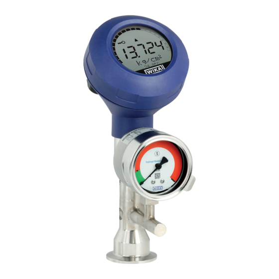
- Page 1 Operating instructions Betriebsanleitung ® Diaphragm monitoring system with HART protocol Model DMSU21SA, for sanitary applications ® Membranüberwachungssystem mit HART -Protokoll Typ DMSU21SA, für die sterile Verfahrenstechnik Example of diaphragm monitoring system, model DMSU21A...
- Page 2 3 - 68 Betriebsanleitung Typ DMSU21A Seite 69 - 134 Further languages can be found at www.wika.com. © 09/2021 WIKA Alexander Wiegand SE & Co. KG All rights reserved. / Alle Rechte vorbehalten. ® WIKA is a registered trademark in various countries.
- Page 3 6.4 Setting the main display ..... . 6.5 Setting the additional display ....WIKA operating instructions, model DMSU21A...
- Page 4 10.8.3 Alarm signal via current loop......... 49 WIKA operating instructions, model DMSU21A...
- Page 5 Annex 2: Menu tree, display Annex 3: Menu tree, diagnosis Annex 4: Menu tree, detailed setting Annex 5: Menu tree, info Annex 6: EU declaration of conformity Declarations of conformity can be found online at www.wika.com WIKA operating instructions, model DMSU21A...
- Page 6 The general terms and conditions contained in the sales documentation shall apply. ■ Subject to technical modifications. ■ Further information: - Internet address: www.wika.de / www.wika.com - Relevant data sheet: DS 95.11 - Application consultant: Tel.: +49 9372 132-0 Fax: +49 9372 132-406 info@wika.de WIKA operating instructions, model DMSU21A...
- Page 7 The process transmitter built into the diaphragm monitoring system processes the pressure prevailing at the process connection and converts it into a current signal or a HART signal. This signal can be used for the evaluation, control and regulation of the process. WIKA operating instructions, model DMSU21A...
- Page 8 → See chapter 10.8 “Alarm status of diaphragm monitoring” for signal processing within the process transmitter Measuring range scaling (turndown) The start and end of the measuring range can be set within defined ranges. WIKA operating instructions, model DMSU21A...
- Page 9 90° steps. Thus the measured value can be read irrespective of the mounting position. 2.3 Scope of delivery Diaphragm monitoring system ■ Operating instructions ■ Cross-check scope of delivery with delivery note. WIKA operating instructions, model DMSU21A...
- Page 10 The measuring technology of the instrument withstands the process pressure despite the diaphragm rupture. The measuring function of the process transmitter is maintained without restrictions. WIKA operating instructions, model DMSU21A...
- Page 11 1. Hot surfaces The surface of the diaphragm seal system can heat up due to the temperature of the process medium. This depends on the installation situation and must be taken into account by the operator. WIKA operating instructions, model DMSU21A...
- Page 12 Risk of injury should qualification be insufficient Improper handling can result in considerable injury and damage to property. ▶ The activities described in this document may only be carried out by skilled personnel who have the qualifications described below. WIKA operating instructions, model DMSU21A...
- Page 13 HW 1.1.0 FW 1.2.3 + : L+ - : L- Prozess/Ambient Temperature: see manual and approval documents WIKA A. Wiegand SE & Co. KG, D-63911 Klingenberg Model S# Serial no. Measuring range P# Product no.
- Page 14 3. Safety Product label, display and operating unit DI-PT DI-PT-UYZZZ-Z WIKA A. Wiegand SE & Co. KG D-63911 Klingenberg Model Model code Date of manufacture YYYY-MM S# Serial no. Symbols Before mounting and commissioning the instrument, ensure you read the...
- Page 15 > 300 °C [572 °F] n. a. Glycerine with FDA approval > 170 °C [338 °F] n. d. KN17 Silicone oil PD5 > 100 °C [212 °F] > 420 °C [788 °F] KN21 Halocarbon n. a. n. a. WIKA operating instructions, model DMSU21A...
- Page 16 Sealings for connections per ISO 2852, DIN 32676 and BS 4825 part 3 are, e.g., manufactured by Combifit International B.V. A manufacturer of sealings for connections per DIN 11851 is, e.g., Kieselmann GmbH. WIKA operating instructions, model DMSU21A...
- Page 17 If the original packaging is not available, then store the instrument in a container that is similar to the original packaging, so that the instrument can't be scratched and is protected against damage if dropped. WIKA operating instructions, model DMSU21A...
- Page 18 ■ “Specifications”. Sufficient space for a safe electrical installation. ■ Operating elements can be accessed following the mounting. ■ Observe the permissible medium and ambient temperatures. These are constituent ■ elements of the order confirmation. WIKA operating instructions, model DMSU21A...
- Page 19 The mounting position must not form a draining point or cause a basin to be formed. ■ With the process connection via an instrumentation T-piece, the branch L of the ■ T-piece must not be longer than the diameter D of the T-piece (L ≤ D). WIKA operating instructions, model DMSU21A...
- Page 20 Angular connector DIN 175301-803A Cable diameter: 6 ... 8 mm [0.24 ... 0.31 in] with mating connector Wire cross-section: max. 1.5 mm² (AWG 16) Circular connector M12 x 1 (4-pin) Observe manufacturer's specifications without mating connector WIKA operating instructions, model DMSU21A...
- Page 21 The process transmitter must be shielded and grounded in accordance with the grounding concept of the plant. ▶ Connect the cable shield with the equipotential bonding. ▶ Connect the process connection or the external grounding screw with the equipotential bonding WIKA operating instructions, model DMSU21A...
- Page 22 Cable gland M20 x 1.5 and spring-loaded terminals Outlet for connection cable Pin assignment Cable gland Positive power supply terminal U+ Shield Negative power supply terminal U- WIKA operating instructions, model DMSU21A...
- Page 23 Enter key [↵] Direction key [▼] The alarm status of the diaphragm monitoring is also shown on the LC display. → See chapter 10.8.1 “Alarm signal on the display and operating unit”. WIKA operating instructions, model DMSU21A...
- Page 24 (0°, 90°, 180°, 270°). Removal Pull out the display and operating unit and attach the push-on cap 3. Screw on the case head cover. Ensure that the case head is tightly closed. WIKA operating instructions, model DMSU21A...
- Page 25 Output signal is displayed as a percentage. ■ Sensor temperature Temperature at the sensor is displayed. ■ PV (primary value) The value corresponding to the mode will be displayed. ■ If the mode is changed, then the main display will change. WIKA operating instructions, model DMSU21A...
- Page 26 1. Open the operating menu with [↵]. Select “Display” and confirm with [↵]. 2. Select “Additional display” and confirm with [↵]. 3. Select value and confirm with [↵]. » Additional display indicates the selected value. WIKA operating instructions, model DMSU21A...
- Page 27 (e.g. AMS or Simatic PDM) or a hand-held (e.g. FC475 from Emerson). The operation of the respective menus is described in the associated online help. The device drivers are available for download from www.wika.com. ® Connecting process transmitter to PC (HART Any work should only be carried out in a safe area.
- Page 28 Length unit for the fill level is known. ■ The density of the medium is known ■ 1. Open the operating menu with [↵]. Select “Basic setting” and confirm with [↵]. 2. Select “Application” and confirm with [↵]. WIKA operating instructions, model DMSU21A...
- Page 29 11. Go back two menu levels using [ESC]. Select “Mode” and confirm with [↵]. 12. Select “Level” and confirm with [↵]. » Mode is set. 13. Perform a mounting correction. → See chapter 8.8 “Mounting correction (offset)”. » Level measurement is configured. WIKA operating instructions, model DMSU21A...
- Page 30 » Repeat for each digit. » Density value is set. 11. Go back two menu levels using [ESC]. Select “Mode” and confirm with [↵]. 12. Select “Level” and confirm with [↵]. » Mode is set. WIKA operating instructions, model DMSU21A...
- Page 31 22. Select “Unit” and confirm with [↵]. 23. Select volume unit and confirm with [↵]. Volume unit: Standard units (e.g. litres, m³, ...) ■ Free input: Freely definable unit (selectable under ■ “Volume unit”) » Volume unit is set. WIKA operating instructions, model DMSU21A...
- Page 32 29. Go back one menu level using [ESC]. Select “Volume” and confirm with [↵]. » Mode is set to volume. 30. Perform a mounting correction. → See chapter 8.8 “Mounting correction (offset)”. » Volume measurement is configured. WIKA operating instructions, model DMSU21A...
- Page 33 8. Configuration via display and operating unit 8.4 Characteristic curves Linear Used for vertical tanks. Horizontal tank Used for horizontal tanks. Spherical tank Used for spherical tanks. WIKA operating instructions, model DMSU21A...
- Page 34 Select “Basic setting” and confirm with [↵]. 2. Select “Application” and confirm with [↵]. 3. Select “Pressure” and confirm with [↵]. 4. Select “Unit” and confirm with [↵]. 5. Select pressure unit and confirm with [↵]. » Pressure unit is set. WIKA operating instructions, model DMSU21A...
- Page 35 5. Select “Unit” and confirm with [↵]. 6. Select volume unit and confirm with [↵]. Volume unit: Standard units (e.g. litres, m³, ...) ■ Free input: Freely definable unit (selectable under ■ “Volume unit”) » Volume unit is set. WIKA operating instructions, model DMSU21A...
- Page 36 1. Open the operating menu with [↵]. Select “Basic setting” and confirm with [↵]. 2. Select “Application” and confirm with [↵]. 3. Select “Sensor temp.” and confirm with [↵]. 4. Select temperature unit and confirm with [↵]. »Temperature unit is set. WIKA operating instructions, model DMSU21A...
- Page 37 2. With the input of current values that are not either 4 mA or 20 mA the pressure value is converted into the standardised current signals as soon as the current value entered is accepted. WIKA operating instructions, model DMSU21A...
- Page 38 2. With the input of current values that are not either 4 mA or 20 mA the pressure value is converted into the standardised current signals as soon as the current value entered is accepted. WIKA operating instructions, model DMSU21A...
- Page 39 1. Open the operating menu with [↵]. Select “Basic setting” and confirm with [↵]. 2. Select “Application” and confirm with [↵]. 3. Select “Pressure” and confirm with [↵]. 4. Select “Mounting corr.” and confirm with [↵]. WIKA operating instructions, model DMSU21A...
- Page 40 The damping prevents the fluctuation of the output signal when there are short-term fluctuations in the measured value. Safety shut-downs due to turbulent processes are thus prevented. Pressure spikes will still be registered, e.g. as P in the menu point “Diagnostic”. WIKA operating instructions, model DMSU21A...
- Page 41 3. Select “on/off” and confirm with [↵]. 4. Activating the write protection: Select “on” and confirm with [↵]. Deactivating the write protection: Select “off” and confirm with [↵]. Enter PIN and confirm with [↵]. » Write protection is activated/deactivated. WIKA operating instructions, model DMSU21A...
- Page 42 3. Select “Press. simu.” and confirm with [↵]. 4. Change digit using [▲] [▼] and confirm with [↵]. The cursor moves to the next digit. Repeat for each digit. » Simulation is active. 5. Ending the simulation. Press [ESC] to do this. WIKA operating instructions, model DMSU21A...
- Page 43 Select “Diagnostic” and confirm with [↵]. 2. Select “Drag pointer” and confirm with [↵]. 3. Select “P min/max” and confirm with [↵]. 4. Select “display” and confirm with [↵]. » Limit values are displayed. ▼ ▲ WIKA operating instructions, model DMSU21A...
- Page 44 Displays the operating time since the last reset. Displaying 1. Open the operating menu with [↵]. Select “Diagnostic” and confirm with [↵]. 2. Select “Operat. time” and confirm with [↵]. 3. Select “display” and confirm with [↵]. » Operating time is displayed. WIKA operating instructions, model DMSU21A...
- Page 45 TAG short enables 8 figures with a limited character set (numbers and capital letters). TAG short can be displayed in the additional display. 1. Open the operating menu with [↵]. Select “Detail setup” and confirm with [↵]. 2. Select “Marking” and confirm with [↵]. WIKA operating instructions, model DMSU21A...
- Page 46 2. Select “Current out” and confirm with [↵]. 3. Select “Alarm signal” and confirm with [↵]. 4. Select alarm signal and confirm with [↵]. 3.5 mA = alarm signal downscale 21.5 mA = alarm signal upscale » Alarm signal is set. WIKA operating instructions, model DMSU21A...
- Page 47 3. Change figure using [▲] [▼] and confirm with [↵]. » Contrast is set. 10.6 Restoring factory setting 1. Open the operating menu with [↵]. Select “Detail setup” and confirm with [↵]. 2. Select “Reset” and confirm with [↵]. WIKA operating instructions, model DMSU21A...
- Page 48 » Short address is set. 10.7.2 Activating/deactivating constant current The constant current affects the output of current values, e.g. in the additional display 1. Open the operating menu with [↵]. Select “Detail setup” and confirm with [↵]. WIKA operating instructions, model DMSU21A...
- Page 49 The additional display changes to the alarm message with the plain-text message “membrane rupture”. As shown on the right, an additional warning symbol is displayed in the upper area of the LC display. The main display remains unchanged. WIKA operating instructions, model DMSU21A...
- Page 50 See chapter 10.3 “Setting the alarm signal” to change the customer-specific presetting. 11. Instrument information 11.1 Displaying measuring range 1. Open the operating menu with [↵]. Select “Info” and confirm with [↵]. 2. Select “Measuring range” and confirm with [↵]. » Measuring range is displayed. WIKA operating instructions, model DMSU21A...
- Page 51 Select “Info” and confirm with [↵]. 2. Select “Serial number” and confirm with [↵]. » Serial numbers are displayed. S# = Serial number H# = HART serial number (the instrument registers itself with this to the process control system) WIKA operating instructions, model DMSU21A...
- Page 52 Wash or clean the dismounted instrument before returning it, in order to protect personnel and the environment from exposure to residual media. Residual media in dismounted instruments can result in a risk to persons, the environment and equipment. Sufficient precautionary measures must be taken. WIKA operating instructions, model DMSU21A...
- Page 53 Faults Causes Measures Display does not indi- Instrument is not Install the electrical connection and/or the cate anything mounted correctly display and operating unit correctly WIKA operating instructions, model DMSU21A...
- Page 54 In this case, contact the manufacturer. If a return is needed, please follow the instructions given in chapter 14.2 “Return”. WIKA operating instructions, model DMSU21A...
- Page 55 14.2 Return WARNING! Strictly observe the following when shipping the instrument: All instruments delivered to WIKA must be free from any kind of hazardous substances (acids, bases, solutions, etc.). When returning the instrument, use the original packaging or a suitable transport packaging.
- Page 56 For the monitoring element to change the status of the switch contact, the specified set point must be reached for at least 1.5 seconds. This prevents shocks or vibrations from triggering the alarm signal unintentionally. WIKA operating instructions, model DMSU21A...
- Page 57 Maximum current I 100 mA Maximum power P (gas) 1,000 mW Effective internal capaci- 11 nF tance Effective internal inductance 100 μH 15.3 Measuring range Measuring range Measuring range See product label Vacuum resistance Overload safety 1-fold WIKA operating instructions, model DMSU21A...
- Page 58 10 ... 60 °C [50 ... 140 °F] Ingress protection IP65 per IEC/EN 60529 The ingress protection only applies with closed case head and closed cable glands. Explosion protection → See chapter 15.1 “Permissible temperature ranges for Ex versions” WIKA operating instructions, model DMSU21A...
- Page 59 Observe manufacturer's specifications Grounding screw, inside 0.13 ... 2.5 mm² Grounding screw, outside 0.13 ... 4 mm² The stated ingress protection only applies when plugged in using mating connectors that have the appropriate ingress protection. WIKA operating instructions, model DMSU21A...
- Page 60 860 ... 1,060 mbar [86 ... 106 kPa, 12.5 ... 15.4 psi] Air humidity 45 ... 75 % r. h. Characteristic curve Terminal method per IEC 61298-2 determination Curve characteristics Linear Reference mounting position Vertical, diaphragm points downward WIKA operating instructions, model DMSU21A...
- Page 61 Cable diameter: 6 ... 12 mm [0.24 ... 0.47 in] Calibration adapter Description Order number ® 11563206 Calibration adapter TRI-CLAMP , 1 ½" ® Calibration adapter TRI-CLAMP , 2" 14332415 Instruments for on-site calibration → See data sheet DS 95.11 WIKA operating instructions, model DMSU21A...
- Page 62 Density value Offset change apply Volume Scale In change apply High change apply Characteristic Linear Horiz. tank Spherical tank Linear. table Scale Out Unit Volume unit L, m³, gal, in³, ... Free input WIKA operating instructions, model DMSU21A Low 0 %...
- Page 63 Scale Out Unit Volume unit L, m³, gal, in³, ... Free input Low 0 % High 100 % Mode Pressure Level Volume Sensor- °C, °F temp. Damping 0 … 99,9 s value Write On/Off protect Change WIKA operating instructions, model DMSU21A...
- Page 64 Annex 2: Menu tree, display Main Display Pressure display Level Volume Current percent Sensor- temp. Additional Pressure display Level Volume Current percent Sensor- temp. Pmin/max PVmin/max Tmin/max TAG short TAG long blank Min. Bargraph display Max. display WIKA operating instructions, model DMSU21A...
- Page 65 TAG short TAG long Annex 2: Menu tree, display blank Min. Bargraph display Max. display Trend indicator WIKA operating instructions, model DMSU21A...
- Page 66 Annex 3: Menu tree, diagnosis Pressure Diagnostic Simulation simulation Current 4 mA simulation 20 mA Input Drag Pmin/max display pointer reset PVmin/max display reset Tmin/max display reset Operating display time reset WIKA operating instructions, model DMSU21A...
- Page 67 TAG short TAG long Current Alarm signal 3.5 mA output 21.5 mA Limits 3.8 … 20.5 mA 4.0 … 20.0 mA Contrast 0 … 9 Instrument Reset spec. Drag pointer Short HART Input address Constant current WIKA operating instructions, model DMSU21A...
- Page 68 Annex 5: Menu tree, info Measuring Info range Setting Date manufactur. Version Serial no. S# device number H# HART number WIKA operating instructions, model DMSU21A...
- Page 69 6.4 Hauptanzeige einstellen ..... . 6.5 Zusatzanzeige einstellen ..... WIKA Betriebsanleitung, Typ DMSU21A...
-
Page 70: Table Of Contents
10.8.3 Alarmsignal über Stromschleife ........116 WIKA Betriebsanleitung, Typ DMSU21A... - Page 71 Anlage 1: Menübaum, Grundeinstellung Anlage 1: Menübaum, Grundeinstellung Anlage 2: Menübaum, Anzeige Anlage 2: Menübaum, Anzeige Anlage 3: Menübaum, Diagnose Anlage 4: Menübaum, Detaileinstellung Anlage 5: Menübaum, Info Anlage 6: EU-Konformitätserklärung Konformitätserklärungen finden Sie online unter www.wika.de WIKA Betriebsanleitung, Typ DMSU21A...
- Page 72 Es gelten die allgemeinen Geschäftsbedingungen in den Verkaufsunterlagen. ■ Technische Änderungen vorbehalten. ■ Weitere Informationen: - Internet-Adresse: www.wika.de / www.wika.com - Zugehöriges Datenblatt: DS 95.11 - Anwendungsberater: Tel.: +49 9372 132-0 Fax: +49 9372 132-406 info@wika.de WIKA Betriebsanleitung, Typ DMSU21A...
- Page 73 2.2 Beschreibung Der im Membranüberwachungssystem verbaute Prozesstransmitter verarbeitet den am Prozessanschluss anstehenden Druck und wandelt diesen in ein Stromsignal bzw. ein HART -Signal um. Dieses Signal kann zur Auswertung, Steuerung und Regelung des Prozesses verwendet werden. WIKA Betriebsanleitung, Typ DMSU21A...
- Page 74 Das Membranüberwachungssystem überträgt die Messwerte über die Stromschleife oder das analoge Fehlersignal bei Membranbruch. → Siehe Kapitel 10.8 „Alarmstatus der Membranüberwachung“ zur Signalverarbeitung im Prozestransmitter Messbereichsskalierung (Turndown) Messbereichsanfang und Messbereichsende können innerhalb definierter Bereiche eingestellt werden. WIKA Betriebsanleitung, Typ DMSU21A...
- Page 75 Der Prozesstransmitter ist mit einem Gehäusekopf ausgestattet, der sich um 330° drehen lässt. Die Anzeige- und Bedieneinheit lässt sich um jeweils 90° versetzt aufstecken. Dadurch lassen sich die Messwerte unabhängig von der Einbaulage ablesen. 2.3 Lieferumfang Membranüberwachungssystem ■ Betriebsanleitung ■ Lieferumfang mit dem Lieferschein abgleichen. WIKA Betriebsanleitung, Typ DMSU21A...
- Page 76 übermittelt. Das Alarmsignal wird je nach Ausführung über das HART -Protokoll oder als Fehlersignal auf der Stromschleife ausgegeben. Die Messtechnik des Gerätes hält trotz des Membranbruches dem Prozessdruck stand. Die Messfunktion des Prozesstransmitters bleibt ohne Einschränkungen erhalten. WIKA Betriebsanleitung, Typ DMSU21A...
- Page 77 Diese Zündquellen sind für das Druckmittlersystem zu berücksichtigen: 6. Heiße Oberflächen Durch die Temperatur des Prozessmediums kann sich die Oberfläche des Druck- mittlersystems erwärmen. Dies ist von der Einbausituation abhängig und muss vom Betreiber berücksichtigt werden. WIKA Betriebsanleitung, Typ DMSU21A...
- Page 78 Werkstoffe sind der Gerätekennzeichnung zu entnehmen. 3.5 Personalqualifikation WARNUNG! Verletzungsgefahr bei unzureichender Qualifikation Unsachgemäßer Umgang kann zu erheblichen Personen- und Sachschäden führen. ▶ Die in diesem Dokument beschriebenen Tätigkeiten nur durch Fachpersonal nachfolgend beschriebener Qualifikation durchführen lassen. WIKA Betriebsanleitung, Typ DMSU21A...
- Page 79 DC 14...30 V 14474869 HW 1.1.0 FW 1.2.3 + : L+ - : L- Prozess/Ambient Temperature: see manual and approval documents WIKA A. Wiegand SE & Co. KG, D-63911 Klingenberg S# Serien-Nr. Messbereich P# Erzeugnis-Nr. Ausgangssignal Hardware- und Firmwareversionen ...
- Page 80 3. Sicherheit Typenschild, Anzeige- und Bedieneinheit DI-PT DI-PT-UYZZZ-Z WIKA A. Wiegand SE & Co. KG D-63911 Klingenberg Typcode Herstelldatum JJJJ-MM S# Serien-Nr. Symbole Vor Montage und Inbetriebnahme des Gerätes unbedingt die Betriebsanleitung lesen!
- Page 81 > 300 °C [572 °F] n. a. Glyzerin mit FDA-Zulassung > 170 °C [338 °F] n. d. Silikonöl PD5 > 100 °C [212 °F] > 420 °C [788 °F] KN17 KN21 Halocarbon n. a. n. a. WIKA Betriebsanleitung, Typ DMSU21A...
- Page 82 Dichtungen für Verbindungen nach ISO 2852, DIN 32676 und BS 4825 Part 3 werden z. B. von der Fa. Combifit International B.V. hergestellt. Hersteller von Dichtungen für Verbindungen nach DIN 11851 ist z. B. die Fa. Kieselmann GmbH. WIKA Betriebsanleitung, Typ DMSU21A...
- Page 83 Membranüberwachungssystem in der Originalverpackung an einem Ort lagern, der die oben gelisteten Bedingungen erfüllt. Wenn die Originalverpackung nicht vorhanden ist, dann das Gerät in einem zur Originalverpackung vergleichbaren Behälter aufbewahren, so dass das Gerät nicht verkratzt werden kann und gegen Schäden durch Herunterfallen geschützt ist. WIKA Betriebsanleitung, Typ DMSU21A...
- Page 84 Mechanische Vibration/mechanischer Schock innerhalb der zulässigen Werte, siehe ■ Kapitel 15 „Technische Daten“. Ausreichend Platz für eine sichere elektrische Installation. ■ Bedienelemente sind nach der Montage erreichbar. ■ Zulässige Temperaturen für Messstoff und Umgebung einhalten. Diese sind ■ Bestandteil der Auftragsbestätigung. WIKA Betriebsanleitung, Typ DMSU21A...
- Page 85 Einbaulage darf keine schöpfende Stelle bilden oder eine Spülbeckenbildung ■ verursachen. Bei der Prozessanbindung über ein Instrumentierungs-T-Stück darf der Abzweig L des ■ T-Stückes nicht länger sein als der Durchmesser D des T-Stückes (L ≤ D). WIKA Betriebsanleitung, Typ DMSU21A...
- Page 86 Kabeldurchmesser: 6 ... 12 mm [0,24 ... 0,47 in] CrNi-Stahl in Hygienic Design Winkelstecker DIN 175301-803A Kabeldurchmesser: 6 ... 8 mm [0,24 ... 0,31 in] Aderquerschnitt: max. 1,5 mm² (AWG 16) mit Gegenstecker Rundstecker M12 x 1 (4-polig) Spezifikationen gem. Hersteller beachten ohne Gegenstecker WIKA Betriebsanleitung, Typ DMSU21A...
- Page 87 Gehäusekopfdeckel mittels Gabelschlüssel abschrauben und Anzeige- und Bedieneinheit bzw. Aufsteckkappe abziehen. 5.5.4 Schirmung und Erdung Der Prozesstransmitter muss entsprechend dem Erdungskonzept der Anlage geschirmt und geerdet werden. ▶ Kabelschirm mit Potentialausgleich verbinden. ▶ Prozessanschluss oder außenliegende Erdungsschraube mit Potentialausgleich verbinden. WIKA Betriebsanleitung, Typ DMSU21A...
- Page 88 Dichtungsnut liegt (keine Lücke zwischen Deckel und Gehäuse). 5.6 Anschlussbelegungen Kabelverschraubung M20 x 1,5 und Federkraftklemmen Zugang für Anschlusskabel Anschlussbelegung Kabelverschraubung Positiver Versorgungsanschluss U+ Schirm Negativer Versorgungsanschluss U- WIKA Betriebsanleitung, Typ DMSU21A...
- Page 89 Bargraph mit Über-/Unterlastpfeilen und Schleppzeigerfunktion ↵ Eingabetaste [ Richtungstaste [▼] Der Alarmstatus der Membranüberwachung wird auch auf der LC-Anzeige dargestellt. → Siehe Kapitel 10.8.1 „Alarmsignal an der Anzeige- und Bedieneinheit“. WIKA Betriebsanleitung, Typ DMSU21A...
- Page 90 Gehäusekopfdeckel mittels Gabelschlüssel abschrauben 2. Einbau Aufsteckkappe abziehen und Anzeige- und Bedieneinheit in beliebiger Rastposition (0°, 90°, 180°, 270°) aufstecken. Ausbau Anzeige- und Bedieneinheit abziehen und Aufsteckkappe aufstecken 3. Gehäusekopfdeckel verschrauben. Sicherstellen, dass Gehäusekopf dicht verschlossen ist. WIKA Betriebsanleitung, Typ DMSU21A...
- Page 91 Ausgangssignal wird angezeigt. ■ PV-Prozent Ausgangssignal als prozentualer Anteil wird angezeigt. ■ Sensortemperatur Temperatur am Sensor wird angezeigt. ■ PV (Primary Value) Dem Modus entsprechender Wert wird angezeigt. ■ Wird der Modus verändert, ändert sich auch die Hauptanzeige. WIKA Betriebsanleitung, Typ DMSU21A...
- Page 92 ■ Leer (Zusatzanzeige ausgeschaltet) ■ 1. Bedienmenü mit [↵] öffnen. „Anzeige“ auswählen und mit [↵] bestätigen. 2. „Zusatzanzeige“ auswählen und mit [↵] bestätigen. 3. Wert auswählen und mit [↵] bestätigen. » Zusatzanzeige zeigt ausgewählten Wert an. WIKA Betriebsanleitung, Typ DMSU21A...
-
Page 93: Konfiguration Über Hart -Schnittstelle
AMS oder Simatic PDM) oder einem Hand-Held (z. B. FC475 von Emerson) bedient und konfiguriert werden. Die Bedienung der jeweiligen Menüs wird in den zugehörigen Online-Hilfen beschrieben. Die Gerätetreiber stehen auf www.wika.de zum Download bereit. ® Prozesstransmitter mit PC verbinden (HART Alle Arbeiten nur im sicheren Bereich durchführen. -
Page 94: Konfiguration Über Anzeige- Und Bedieneinheit
» Druckmessung ist konfiguriert. 8.2 Füllstandsmessung konfigurieren Voraussetzung Längeneinheit für Füllstandshöhe ist bekannt. ■ Dichte des Messstoffes ist bekannt ■ 1. Bedienmenü mit [↵] öffnen. „Grundeinstell.“ auswählen und mit [↵] bestätigen. 2. „Anwendung“ auswählen und mit [↵] bestätigen. WIKA Betriebsanleitung, Typ DMSU21A... - Page 95 11. Mit [ESC] zwei Menüebenen zurückspringen. „Modus“ auswählen und mit [↵] bestätigen. 12. „Füllstand“ auswählen und mit [↵] bestätigen. » Modus ist eingestellt. 13. Lagekorrektur durchführen. → Siehe Kapitel 8.8 „Lagekorrektur (Offset)“. » Füllstandsmessung ist konfiguriert. WIKA Betriebsanleitung, Typ DMSU21A...
-
Page 96: Volumenmessung Konfigurieren
» Cursor springt zur nächsten Ziffer. » Vorgang für alle Ziffern wiederholen. » Dichtewert ist eingestellt. 11. Mit [ESC] zwei Menüebenen zurückspringen. „Volumen“ auswählen und mit [↵] bestätigen. 12. „Scale In“ auswählen und mit [↵] bestätigen. WIKA Betriebsanleitung, Typ DMSU21A... - Page 97 21. „Scale Out“ auswählen und mit [↵] bestätigen. 22. „Einheit“ auswählen und mit [↵] bestätigen. 23. Volumeneinheit auswählen und mit [↵] bestätigen. Volumeneinheit: Standardeinheiten (z. B. Liter, m³, ...) ■ Freie Eingabe: frei definierbare Einheit (auswählbar unter ■ „Volumeneinheit“) » Volumeneinheit ist eingestellt. WIKA Betriebsanleitung, Typ DMSU21A...
- Page 98 „Modus“ auswählen und mit [↵] bestätigen. 29. Mit [ESC] eine Menüebene zurückspringen. „Volumen“ auswählen und mit [↵] bestätigen. » Modus ist auf Volumen eingestellt. 30. Lagekorrektur durchführen. → Siehe Kapitel 8.8 „Lagekorrektur (Offset)“. » Volumenmessung ist konfiguriert. WIKA Betriebsanleitung, Typ DMSU21A...
-
Page 99: Kennlinien
8. Konfiguration über Anzeige- und Bedieneinheit 8.4 Kennlinien Linear Wird bei stehenden Tanks verwendet. Tank liegend Wird bei liegenden Tanks verwendet. Kugeltank Wird bei kugelförmigen Tanks verwendet. WIKA Betriebsanleitung, Typ DMSU21A... -
Page 100: Einheiten Einstellen
„Grundeinstell.“ auswählen und mit [↵] bestätigen. 2. „Anwendung“ auswählen und mit [↵] bestätigen. 3. „Druck“ auswählen und mit [↵] bestätigen. 4. „Einheit“ auswählen und mit [↵] bestätigen. 5. Druckeinheit auswählen und mit [↵] bestätigen. » Druckeinheit ist eingestellt. WIKA Betriebsanleitung, Typ DMSU21A... -
Page 101: Längeneinheit Einstellen (Zur Füllstandsmessung)
4. „Scale Out“ auswählen und mit [↵] bestätigen. 5. „Einheit“ auswählen und mit [↵] bestätigen. 6. Volumeneinheit auswählen und mit [↵] bestätigen. Volumeneinheit: Standardeinheiten (z. B. Liter, m³, ...) ■ Freie Eingabe: frei definierbare Einheit (auswählbar unter ■ „Volumeneinheit“) » Volumeneinheit ist eingestellt. WIKA Betriebsanleitung, Typ DMSU21A... -
Page 102: Dichteeinheit Und Dichtewert Einstellen
Temperatureinheit °C und °F auswählbar. 1. Bedienmenü mit [↵] öffnen. „Grundeinstell.“ auswählen und mit [↵] bestätigen. 2. „Anwendung“ auswählen und mit [↵] bestätigen. 3. „Sensortemp.“ auswählen und mit [↵] bestätigen. 4. Temperatureinheit auswählen und mit [↵] bestätigen. »Temperatureinheit ist eingestellt. WIKA Betriebsanleitung, Typ DMSU21A... -
Page 103: Messbereich Skalieren
Wird letzte Ziffer quittiert, springt das Menü zurück zu Schritt 2. Bei Eingabe von Stromwerten abweichend von 4 mA bzw. 20 mA wird der Druckwert auf die normierten Stromsignale umgerechnet sobald der eingegebene Stromwert übernommen ist. WIKA Betriebsanleitung, Typ DMSU21A... -
Page 104: Trockenabgleich Durchführen
Wird letzte Ziffer quittiert, springt das Menü zurück zu Schritt 2. Bei Eingabe von Stromwerten abweichend von 4 mA bzw. 20 mA wird der Druckwert auf die normierten Stromsignale umgerechnet sobald der eingegebene Stromwert übernommen ist. WIKA Betriebsanleitung, Typ DMSU21A... -
Page 105: Modus Einstellen
■ geeignetes Equipment durchführen. 1. Bedienmenü mit [↵] öffnen. „Grundeinstell.“ auswählen und mit [↵] bestätigen. 2. „Anwendung“ auswählen und mit [↵] bestätigen. 3. „Druck“ auswählen und mit [↵] bestätigen. 4. „Lagekorrektur“ auswählen und mit [↵] bestätigen. WIKA Betriebsanleitung, Typ DMSU21A... -
Page 106: Trockenabgleich Durchführen
» Eingegebener Wert wird als neuer Nullpunkt verwendet. 8.9 Dämpfung einstellen Die Dämpfung verhindert Schwankungen des Ausgangssignals, bei kurzzeitigen Messwertschwankungen. Sicherheitsabschaltungen auf Grund von unruhigem Prozess werden damit unterbunden. Druckspitzen werden trotzdem registriert, z. B. als P im Menüpunkt „Diagnose“. WIKA Betriebsanleitung, Typ DMSU21A... -
Page 107: Schreibschutz
2. „Schreibschutz“ auswählen und mit [↵] bestätigen. 3. „ein/aus“ auswählen und mit [↵] bestätigen. 4. Scheibschutz aktivieren: „ein“ auswählen und mit [↵] bestätigen. Scheibschutz deaktivieren: „aus“ auswählen und mit [↵] bestätigen. PIN eingeben und mit [↵] bestätigen. » Schreibschutz ist aktiviert/deaktiviert. WIKA Betriebsanleitung, Typ DMSU21A... -
Page 108: Pin Ändern
3. „Drucksimul.“ auswählen und mit [↵] bestätigen. 4. Ziffer über [▲] [▼] verändern und mit [↵] bestätigen. Cursor springt zur nächsten Ziffer. Vorgang für alle Ziffern wiederholen. » Simulation ist aktiv. 5. Simulation beenden. Dazu [ESC] betätigen. WIKA Betriebsanleitung, Typ DMSU21A... -
Page 109: Stromsimulation Durchführen
1. Bedienmenü mit [↵] öffnen. „Diagnose“ auswählen und mit [↵] bestätigen. 2. „Schleppzeiger“ auswählen und mit [↵] bestätigen. 3. „P min/max“ auswählen und mit [↵] bestätigen. 4. „anzeigen“ auswählen und mit [↵] bestätigen. » Grenzwerte werden angezeigt. ▼ ▲ WIKA Betriebsanleitung, Typ DMSU21A... -
Page 110: Schleppzeiger Pv
Zeigt die Betriebsdauer seit dem letzten Zurücksetzen an. Anzeigen 1. Bedienmenü mit [↵] öffnen. „Diagnose“ auswählen und mit [↵] bestätigen. 2. „Betriebsdauer“ auswählen und mit [↵] bestätigen. 3. „anzeigen“ auswählen und mit [↵] bestätigen. » Betriebsdauer wird angezeigt. WIKA Betriebsanleitung, Typ DMSU21A... -
Page 111: Detaileinstellungen
10.2.1 TAG-kurz einstellen TAG-kurz erlaubt 8 Stellen mit eingeschränktem Zeichensatz (Zahlen und Großbuchstaben). TAG-kurz kann auf der Zusatzanzeige angezeigt werden. 1. Bedienmenü mit [↵] öffnen. „Detaileinstel.“ auswählen und mit [↵] bestätigen. 2. „Kennzeichnung“ auswählen und mit [↵] bestätigen. WIKA Betriebsanleitung, Typ DMSU21A... -
Page 112: Tag-Lang Einstellen
„Detaileinstel.“ auswählen und mit [↵] bestätigen. 2. „Stromausgang“ auswählen und mit [↵] bestätigen. 3. „Alarmsignal“ auswählen und mit [↵] bestätigen. 4. Alarmsignal auswählen und mit [↵] bestätigen. 3,5 mA = Alarmsignal zusteuernd 21,5 mA = Alarmsignal aufsteuernd » Alarmsignal ist eingestellt. WIKA Betriebsanleitung, Typ DMSU21A... -
Page 113: Signalgrenzen Einstellen
2. „Kontrast“ auswählen und mit [↵] bestätigen. 3. Stelle über [▲] [▼] verändern und mit [↵] bestätigen. » Kontrast ist eingestellt. 10.6 Werkseinstellung wiederherstellen 1. Bedienmenü mit [↵] öffnen. „Detaileinstel.“ auswählen und mit [↵] bestätigen. 2. „Reset“ auswählen und mit [↵] bestätigen. WIKA Betriebsanleitung, Typ DMSU21A... -
Page 114: Hart
4. Ziffer über [▲] [▼] verändern und mit [↵] bestätigen. Cursor springt zur nächsten Ziffer. Vorgang für alle Ziffern wiederholen. » Kurzadresse ist eingestellt. 10.7.2 Strom konstant aktivieren/deaktivieren Strom konstant beeinflusst die Ausgabe von Stromwerten, z. B. auf der Zusatzanzeige WIKA Betriebsanleitung, Typ DMSU21A... -
Page 115: Alarmstatus Der Membranüberwachung
→ Siehe Kapitel 14 „Demontage, Rücksendung und Entsorgung“. 10.8.1 Alarmmeldung an der Anzeige- und Bedieneinheit Die Zusatzanzeige wechselt zur Alarmmeldung in Klartext „Membranbruch“. Wie rechts dargestellt, wird im oberen Bereich der LC-Anzeige zusätzlich ein Warnsymbol eingeblendet. Die Hauptanzeige wird unverändert dargestellt. WIKA Betriebsanleitung, Typ DMSU21A... -
Page 116: Alarmsignal Über Hart -Kommunikation
Siehe Kapitel 10.3 „Alarmsignal einstellen“ zum Ändern der Voreinstellung. 11. Geräteinformationen 11.1 Messbereich anzeigen 1. Bedienmenü mit [↵] öffnen. „Info“ auswählen und mit [↵] bestätigen. 2. „Messbereich“ auswählen und mit [↵] bestätigen. » Messbereich wird angezeigt. WIKA Betriebsanleitung, Typ DMSU21A... -
Page 117: Herstelldatum Anzeigen
11.4 Seriennummer anzeigen 1. Bedienmenü mit [↵] öffnen. „Info“ auswählen und mit [↵] bestätigen. 2. „Seriennummer“ auswählen und mit [↵] bestätigen. » Seriennummern werden angezeigt. S# = Seriennummer H# = HART-Seriennummer (das Gerät meldet sich damit im Prozessleitsystem) WIKA Betriebsanleitung, Typ DMSU21A... -
Page 118: Reinigung, Wartung Und Rekalibrierung
Ausgebautes Gerät vor der Rücksendung spülen bzw. säubern, um Mitarbeiter und Umwelt vor Gefährdung durch anhaftende Messstoffreste zu schützen. Messstoffreste in ausgebauten Geräten können zur Gefährdung von Personen, Umwelt und Einrichtung führen. Ausreichende Vorsichtsmaßnahmen sind zu ergreifen. WIKA Betriebsanleitung, Typ DMSU21A... -
Page 119: Reinigungsprozess Cleaning-In-Place (Cip)
Bei Geräten mit Anzeige- und Bedieneinheit wird im Fehlerfall der Fehlercode mit Fehlertext angezeigt. Störungen Ursachen Maßnahmen Anzeige zeigt nichts an Gerät ist nicht korrekt Elektrischen Anschluss und/oder Anzeige- montiert und Bedieneinheit richtig montieren WIKA Betriebsanleitung, Typ DMSU21A... - Page 120 Gerät unverzüglich außer Betrieb zu setzen, sicherzustellen, dass kein Druck bzw. Signal mehr anliegt und gegen versehentliche Inbetriebnahme zu schützen. In diesem Falle Kontakt mit dem Hersteller aufnehmen. Bei notwendiger Rücksendung die Hinweise unter Kapitel 14.2 „Rücksendung“ beachten. WIKA Betriebsanleitung, Typ DMSU21A...
-
Page 121: Demontage, Rücksendung Und Entsorgung
Membranüberwachungssystem vor der Demontage druck- und stromlos schalten. 14.2 Rücksendung WARNUNG! Beim Versand des Gerätes unbedingt beachten: Alle an WIKA gelieferten Geräte müssen frei von Gefahrstoffen (Säuren, Laugen, Lösungen, etc.) sein. Zur Rücksendung des Gerätes die Originalverpackung oder eine geeignete Transportverpackung verwenden. -
Page 122: Technische Daten
→ Siehe Kapitel 10.8 „Alarmstatus der Membranüberwachung“ Bedingung Alarmsigal Damit das Überwachungselement den Status des Schaltkon- taktes ändert, muss der vorgegebene Sollwert mindestens 1,5 Sekunden lang erreicht werden. Dadurch wird vermieden, dass Schocks oder Vibrationen das Alarmsignal ungewollt auslösen. WIKA Betriebsanleitung, Typ DMSU21A... -
Page 123: Zulässige Temperaturbereiche Für Ex-Ausführungen
Maximale Spannung U DC 30 V Maximaler Strom I 100 mA Maximale Leistung P (Gas) 1.000 mW Innere wirksame Kapazität 11 nF Innere wirksame Induktivität 100 μH 15.3 Messbereich Messbereich Messbereich Siehe Typenschild Vakuumfestigkeit Überlastsicherheit 1-fach WIKA Betriebsanleitung, Typ DMSU21A... -
Page 124: Genauigkeitsangaben
-10 ... +150 °C [14 ... 302 °F] ■ Lagerung 10 ... 60 °C [50 ... 140 °F] Schutzart nach IEC/EN 60529 IP65 Die Schutzart gilt nur bei geschlossenem Gehäusekopf und geschlossenen Kabelverschraubungen. Explosionsschutz → Siehe Kapitel 15.1 „Zulässige Temperaturbereiche für Ex-Ausführungen“ WIKA Betriebsanleitung, Typ DMSU21A... -
Page 125: Anzeige- Und Bedieneinheit, Typ Di-Pt-U
Rundstecker M12 x 1 (4-polig) Schutzart: IP65 ohne Gegenstecker Spezifikationen gem. Hersteller beachten Erdungsschraube, innen 0,13 ... 2,5 mm² Erdungsschraube, außen 0,13 ... 4 mm² Die angegebenen Schutzarten gelten nur im gesteckten Zustand mit Gegensteckern entsprechender Schutzart. WIKA Betriebsanleitung, Typ DMSU21A... -
Page 126: Referenzbedingungen Nach Iec 61298-1
DC 23 ... 25 V Luftdruck 860 ... 1.060 mbar [86 ... 106 kPa, 12,5 ... 15,4 psi] Luftfeuchte 45 ... 75 % r. F. Kennlinienbestimmung Grenzpunkteinstellung nach IEC 61298-2 Kennliniencharakteristik Linear Referenzeinbaulage Stehend, Membrane zeigt nach unten WIKA Betriebsanleitung, Typ DMSU21A... -
Page 127: Zubehör Und Ersatzteile
Hygienegerechte Kabelverschraubung M20 x 1,5 11348691 Kabeldurchmesser: 6 ... 12 mm [0,24 ... 0,47 in] Kalibrieradapter Beschreibung Bestell- nummer ® 11563206 Kalibrieradapter TRI-CLAMP , 1 ½" ® Kalibrieradapter TRI-CLAMP , 2" 14332415 Geräte zur Vor-Ort-Kalibrierung → siehe Datenblatt DS 95.11 WIKA Betriebsanleitung, Typ DMSU21A... -
Page 128: Anlage 1: Menübaum, Grundeinstellung
Dichteeinheit kg/dm³, lb/ft³ Dichtewert Offset ändern übernehmen Volumen Scale In ändern übernehmen High ändern übernehmen Kennlinie Linear Tank liegend Kugeltank Linearisierungs- tabelle Scale Out Einheit Volumeneinheit L, m³, gal, in³, ... Freie Eingabe WIKA Betriebsanleitung, Typ DMSU21A Low 0 %... -
Page 129: Anlage 1: Menübaum, Grundeinstellung
Linearisierungs- tabelle Scale Out Einheit Volumeneinheit L, m³, gal, in³, ... Freie Eingabe Low 0 % High 100 % Modus Druck Füllstand Volumen Sensor- °C, °F temp. Dämpfung 0 … 99,9 s Schreib- Ein/Aus schutz ändern WIKA Betriebsanleitung, Typ DMSU21A... -
Page 130: Anlage 2: Menübaum, Anzeige
Anlage 2: Menübaum, Anzeige Haupt- Anzeige Druck anzeige Füllstand Volumen Strom Prozent Sensor- temp. Zusatz- Druck anzeige Füllstand Volumen Strom Prozent Sensor- temp. Pmin/max PVmin/max Tmin/max TAG-kurz TAG-lang leer Min. Bargraph Anzeige Max. Anzeige WIKA Betriebsanleitung, Typ DMSU21A... -
Page 131: Anlage 2: Menübaum, Anzeige
TAG-kurz TAG-lang Anlage 2: Menübaum, Anzeige leer Min. Bargraph Anzeige Max. Anzeige Trend- anzeige WIKA Betriebsanleitung, Typ DMSU21A... -
Page 132: Anlage 3: Menübaum, Diagnose
Anlage 3: Menübaum, Diagnose Druck- Diagnose Simulation simulaton Strom- 4 mA simulation 20 mA Eingabe Schlepp- Pmin/max anzeigen zeiger rücksetzen PVmin/max anzeigen rücksetzen Tmin/max anzeigen rücksetzen Betriebs- anzeigen dauer rücksetzen WIKA Betriebsanleitung, Typ DMSU21A... -
Page 133: Anlage 4: Menübaum, Detaileinstellung
Espanol Kennzeich- TAG-kurz nung TAG-lang Strom- Alarmsignal 3,5 mA ausgang 21,5 mA Grenzen 3,8 … 20,5 mA 4,0 … 20,0 mA Kontrast 0 … 9 Geräte- Reset daten Schlepp- zeiger Kurz- HART Eingabe adresse Strom konstant WIKA Betriebsanleitung, Typ DMSU21A... -
Page 134: Anlage 5: Menübaum, Info
Anlage 5: Menübaum, Info Info Messbereich Einstellung Herstell- datum Version Seriennr. S# Gerätenummer H# HART-Nummer WIKA Betriebsanleitung, Typ DMSU21A... -
Page 135: Anlage 6: Eu-Konformitätserklärung
Annex 6: EU declaration of conformity WIKA operating instructions, model DMSU21A... - Page 136 WIKA subsidiaries worldwide can be found online at www.wika.com. WIKA-Niederlassungen weltweit finden Sie online unter www.wika.de. WIKA Alexander Wiegand SE & Co. KG Alexander-Wiegand-Straße 30 63911 Klingenberg • Germany Tel. +49 9372 132-0 +49 9372 132-406 info@wika.de www.wika.de WIKA operating instructions, model DMSU21A...
Need help?
Do you have a question about the DMSU21SA and is the answer not in the manual?
Questions and answers