
Related Manuals for Beckhoff EK3100


Summary of Contents for Beckhoff EK3100
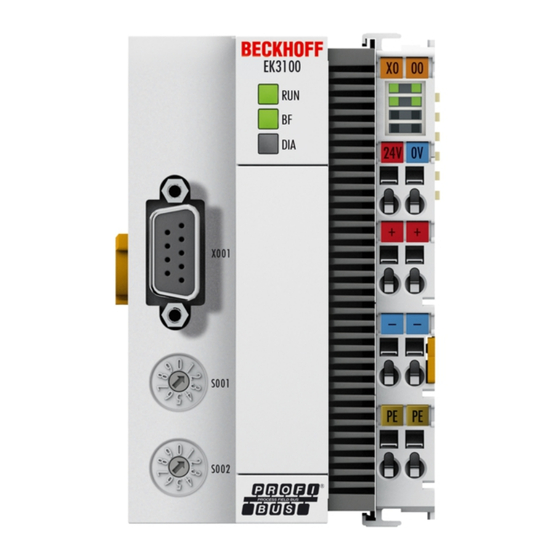
- Page 1 Documentation EK3100 PROFIBUS Bus Coupler for EtherCAT Terminals Version: Date: 2020-04-23...
-
Page 3: Table Of Contents
5.2.4 Configuring EtherCAT Terminals .................. 41 5.2.5 Using Restore file ...................... 42 Configuration in TwinCAT 3...................... 43 5.3.1 Adding the EK3100 Bus Coupler in TwinCAT .............. 43 5.3.2 Using the CtrlStatus DWORD.................. 44 5.3.3 Adding an EtherCAT Terminal.................. 45 5.3.4 Creating a virtual slave .................... 46 EK3100 Version: 1.5... - Page 4 Diagnostics via PROFIBUS ...................... 53 6.3.1 Diagnostics for virtual slaves ................... 53 6.3.2 Configuration of the diagnostic telegram ................. 54 7 Appendix .............................. 55 Update Bus Coupler image ...................... 55 Support and Service ........................ 56 List of tables............................. 57 List of illustations ............................ 58 Version: 1.5 EK3100...
-
Page 5: Foreword
EP1590927, EP1789857, EP1456722, EP2137893, DE102015105702 with corresponding applications or registrations in various other countries. ® EtherCAT is registered trademark and patented technology, licensed by Beckhoff Automation GmbH, Germany. Copyright © Beckhoff Automation GmbH & Co. KG, Germany. The reproduction, distribution and utilization of this document as well as the communication of its contents to others without express authorization are prohibited. -
Page 6: Safety Instructions
All the components are supplied in particular hardware and software configurations appropriate for the application. Modifications to hardware or software configurations other than those described in the documentation are not permitted, and nullify the liability of Beckhoff Automation GmbH & Co. KG. Personnel qualification This description is only intended for trained specialists in control, automation and drive engineering who are familiar with the applicable national standards. -
Page 7: Documentation Issue Status
Foreword Documentation issue status Version Modifications • Update chapter “Technical data” • Update chapter “Configuration” • Update chapter UL notice • Update chapter “Update Bus Coupler image” • Minor corrections & addenda • First version and publication EK3100 Version: 1.5... -
Page 8: Product Overview
The variants from the EKxxxx series differ from one another by the interface for the higher-level fieldbus system. An overview of the various Beckhoff Bus Couplers covering the most important fieldbus systems can be found on the Beckhoff Website. Embedded PCs with fieldbus interface and decentralized control The TwinCAT-programmable variant is the CX80xx Embedded PC series. -
Page 9: Ek3100 - Introduction
EtherCAT Box modules (EPxxxx) and converts the telegrams from PROFIBUS to E-bus signal representation. One station consists of an EK3100 and any number of EtherCAT Terminals. A 9-pin D-sub connector is used for connecting the coupler to PROFIBUS. In EtherCAT, the PROFIBUS coupler has at its disposal a lower- level, powerful and ultra-fast I/O system with a large selection of terminals. -
Page 10: Technical Data - Ek3100
Product overview Technical data - EK3100 Technical data EK3100 Bus interface 1 x D-sub socket, 9-pin with shielding Protocol PROFIBUS DP Data transfer rates up to max. 12 Mbaud (automatic recognition) Interfaces 1 x USB (behind the front flap) Web interface... -
Page 11: Technical Data - Profibus
Product overview Technical data - PROFIBUS Technical data PROFIBUS (EK3100) Number of I/O modules depending on controller Number of I/O points depending on controller Data transfer medium shielded copper cable, 2 x 0.25 mm² Cable length 1200 m 1000 m 400 m 200 m 100 m... -
Page 12: Mounting And Wiring
Fig. 3: Spring contacts of the Beckhoff I/O components Mounting 3.2.1 Dimensions The following illustrations show the dimensions of the Bus Couplers. Drawings in DWF and STEP format can be found in the Download section of the Beckhoff website. Version: 1.5 EK3100... -
Page 13: Installation On Mounting Rails - Bus Coupler
Fig. 5: Snapping onto the mounting rail, based on the EK9300 as an example. NOTE Avoid damage! Do not force the module or apply excessive pressure! Installation positions The installation position of the Bus Coupler is arbitrary. EK3100 Version: 1.5... -
Page 14: Fig. 6 Recommended Distances For Standard Installation Position, Based On The Ek9300 As An Exam- Ple
We recommend the installation in the horizontal position for optimum ventilation. Furthermore, it is not nec- essary with this installation position to check whether there are terminals present that may only be installed horizontally. Other installation positions are allowed, but not recommended. Version: 1.5 EK3100... -
Page 15: Fig. 7 Other Installation Positions, Based On The Ek9300 As An Example
Mounting and wiring Fig. 7: Other installation positions, based on the EK9300 as an example. EK3100 Version: 1.5... -
Page 16: Wiring
10 A. The current carrying capacity between two terminal points is identical to the current carrying capacity of the connecting wires. The spring-loaded terminal points are designed for wires with cross-sections from 0.08 mm² to 2.5 mm². Version: 1.5 EK3100... -
Page 17: Profibus Interface (X001)
The Profibus bus line is connected via a 9-pin D sub with the following pin assignment: Assignment Shielding not used RxD/TxD-P not used +5 V not used RxD/TxD-N not used cable colors PROFIBUS line D sub B red Pin 3 A green Pin 8 EK3100 Version: 1.5... -
Page 18: Cabling
Preassembled cable from BECKHOFF Installation is made a great deal more straightforward if preassembled cables from BECKHOFF are used! Wiring faults are avoided, and commissioning is more rapidly completed. The BECKHOFF range includes fieldbus cables, power supply cables, sensor cables and accessories such as termi- nation resistors and T-pieces. -
Page 19: Fig. 10 Profibus Cabling
3. Resistance between A at the start and A at the end of the line: approx. 0 Ohm 4. Resistance between B at the start and B at the end of the line: approx. 0 Ohm 5. Resistance between shield at the start and shield at the end of the line: approx. 0 Ohm EK3100 Version: 1.5... -
Page 20: Topology
• The maximum number of devices is 125 • Interrupting the supply voltages from cable ends by switching off the repeater/slave, or by pulling out the plug, is not permitted. Fig. 11: PROFIBUS topology with the EK3100 Bus Coupler. Version: 1.5 EK3100... -
Page 21: Ul Notice
Beckhoff EtherCAT modules are intended for use with Beckhoff’s UL Listed EtherCAT Sys- tem only. Examination For cULus examination, the Beckhoff I/O System has only been investigated for risk of fire and electrical shock (in accordance with UL508 and CSA C22.2 No. 142). For devices with Ethernet connectors Not for connection to telecommunication circuits. -
Page 22: Atex - Special Conditions (Standard Temperature Range)
80°C at the wire branching points, then cables must be selected whose tempera- ture data correspond to the actual measured temperature values! • Observe the permissible ambient temperature range of 0 to 55°C for the use of Beckhoff fieldbus compo- nents standard temperature range in potentially explosive areas! •... -
Page 23: Atex - Special Conditions (Extended Temperature Range)
80°C at the wire branching points, then cables must be selected whose tempera- ture data correspond to the actual measured temperature values! • Observe the permissible ambient temperature range of -25 to 60°C for the use of Beckhoff fieldbus com- ponents with extended temperature range (ET) in potentially explosive areas! •... -
Page 24: Continuative Documentation About Explosion Protection
Associated and synonymous with each revision there is usually a description (ESI, EtherCAT Slave Information) in the form of an XML file, which is available for download from the Beckhoff web site. From 2014/01 the revision is shown on the outside of the IP20 terminals, see Fig. “EL5021 EL terminal, standard IP20 IO device with batch number and revision ID (since 2014/01)”. -
Page 25: Fig. 12 El5021 El Terminal, Standard Ip20 Io Device With Serial/ Batch Number And Revision Id (Since 2014/01)
Production lot/batch number/serial number/date code/D number The serial number for Beckhoff IO devices is usually the 8-digit number printed on the device or on a sticker. The serial number indicates the configuration in delivery state and therefore refers to a whole production batch, without distinguishing the individual modules of a batch. -
Page 26: Fig. 13 Ek1100 Ethercat Coupler, Standard Ip20 Io Device With Serial/ Batch Number
Mounting and wiring Fig. 13: EK1100 EtherCAT coupler, standard IP20 IO device with serial/ batch number Fig. 14: CU2016 switch with serial/ batch number Fig. 15: EL3202-0020 with serial/ batch number 26131006 and unique ID-number 204418 Version: 1.5 EK3100... -
Page 27: Fig. 16 Ep1258-00001 Ip67 Ethercat Box With Batch Number/ Date Code 22090101 And Unique Se- Rial Number 158102
Fig. 17: EP1908-0002 IP67 EtherCAT Safety Box with batch number/ date code 071201FF and unique serial number 00346070 Fig. 18: EL2904 IP20 safety terminal with batch number/ date code 50110302 and unique serial number 00331701 Fig. 19: ELM3604-0002 terminal with unique ID number (QR code) 100001051 and serial/ batch number 44160201 EK3100 Version: 1.5... -
Page 28: Beckhoff Identification Code (Bic)
3.8.1 Beckhoff Identification Code (BIC) The Beckhoff Identification Code (BIC) is increasingly being applied to Beckhoff products to uniquely identify the product. The BIC is represented as a Data Matrix Code (DMC, code scheme ECC200), the content is based on the ANSI standard MH10.8.2-2016. - Page 29 Example of composite information from item 1 to 4 and 6. The data identifiers are marked in red for better display: An important component of the BIC is the Beckhoff Traceability Number (BTN, item no. 2). The BTN is a unique serial number consisting of eight characters that will replace all other serial number systems at Beckhoff in the long term (e.g.
-
Page 30: Parameterization And Commissioning
Parameterization and Commissioning USB interface The USB interface of type B is located behind the front flap of the EK3100 Bus Coupler. The internal flash memory can be reached via the USB interface for updating the image, for example. Fig. 21: USB interface of the EK3100 Bus Coupler. -
Page 31: 2-Pin Dip Switch
IP address (via USB interface) The IP address can be used to access the EK3100 Bus Coupler via a host PC. To access the EK3100 Bus Coupler, the corresponding USB driver first has to be installed on the host PC (see: Installing the USB driver [} 36]). -
Page 32: Configuration
• TwinCAT 2: C:\TwinCAT\Io\Profibus • TwinCAT 3: C:\TwinCAT\3.1\Config\Io\Profibus Or: The GSD file for the EK3100 Bus Coupler can be installed retrospectively in TwinCAT when the Bus Coupler is added in TwinCAT (see: Adding the EK3100 Bus Coupler in TwinCAT [} 43]). A corresponding prompt appears in TwinCAT, which asks you to install the GSD file. -
Page 33: Fig. 24 Sample Configuration With Ek1100 Ethercat Coupler
PROFIBUS. The input data of all EtherCAT devices are then invalid and the output data are no longer accepted. This also applies to the devices that are still in operation on the EK3100. If you wish to use the option to plug in or unplug devices during the runtime, a further “Sync Unit”... -
Page 34: Fig. 25 Sample Configuration With Epxxxx Ethercat Box
If EtherCAT junction 1 on the EP1122 is connected, then the EtherCAT frame is forwarded here first (1); if junction 1 is not connected the frame on junction 2 is sent (2), only after that does the sequence continue with the EtherCAT connection on the right-hand side (3). Version: 1.5 EK3100... -
Page 35: Fig. 27 Example Configuration With Ep1122 (2-Port Ethercat Junction In Protection Class Ip65)
• Only EtherCAT devices from Beckhoff are supported. To use EtherCAT device from other manufacturers, use the CX8031 Embedded PC instead. • The EK3100 Bus Coupler does not support hot-plug. All EtherCAT devices have to be connected before the Bus Coupler can be started. The EtherCAT configuration must not be changed during operation. -
Page 36: Beckhoff Device Manager
Install the USB driver as follows: 1. Use a USB cable to connect the EK3100 Bus Coupler to the host PC and start the Bus Coupler. The device Beckhoff Automation GmbH EK Series USB appears in the device manager of the host 2. - Page 37 Configuration ð The USB driver has been installed successfully if the additional Ethernet interface Beckhoff Automation GmbH EK9XXX Series USB RNDIS6 appears in the device manager. In the next step you can start the Beckhoff Device Manager. EK3100 Version: 1.5...
-
Page 38: Starting The Beckhoff Device Manager
• USB driver installed on the host PC (see: Installing the USB driver [} 36]). Start the Beckhoff Device Manager as follows: 1. On the host PC enter the IP address of the Bus Coupler in the web browser, in order to start the Beckhoff Device Manager. -
Page 39: Setting The Mappings For Ethercat Terminals
Beckhoff Device Manager are not considered or are overwritten. In the Beckhoff Device Manager you can set the mapping for an EtherCAT Terminal, if this EtherCAT Terminal supports different mappings. For the analog EL3062 EtherCAT Terminal, for example, you can choose between Standard mapping and Compact mapping. -
Page 40: Fig. 28 Meaning Of The Individual Bits With All Subvariables And Structure Contents For The El3062
The status word (SW) is located in the input process image, and is transmitted from terminal to the controller. SW.15 SW.14 SW.13 SW.12 SW.11 SW.10 SW.9 SW.8 Name TxPDO TxPDO Toggle State SW.7 SW.6 SW.5 SW.4 SW.3 SW.2 SW.1 SW.0 Name ERROR Limit 2 Limit 1 Over- Under- range range Version: 1.5 EK3100... -
Page 41: Configuring Ethercat Terminals
For example, for the EL3062 under: Commissioning > Object description and parameterization > Configuration data. Requirements: • The Beckhoff Device Manager was already started (see: Starting the Beckhoff Device Manager [} 38]). Configure EtherCAT Terminals as follows: 1. Click on EtherCAT, then on Master. -
Page 42: Using Restore File
5.2.5 Using Restore file Restore files are used in the Beckhoff device manager for saving existing EtherCAT Terminal configurations and settings. Without a Restore file, EtherCAT Terminal settings are lost, if the terminal is replaced. If a Restore file was created, the parameters can be copied to a new EtherCAT Terminal when the Bus Coupler is started. -
Page 43: Configuration In Twincat 3
5.3.1 Adding the EK3100 Bus Coupler in TwinCAT The EK3100 Bus Coupler is added in TwinCAT under a PROFIBUS master. In this step the CX2020 Embedded PC is used with a CX2500-M310 PROFIBUS fieldbus module as an example. The EK3100 Bus Coupler requires the appropriate GSD file for TwinCAT. Two options are available. The GSD file can be copied into the TwinCAT directory or added to TwinCAT retrospectively. -
Page 44: Using The Ctrlstatus Dword
0x10 E-bus fixed after error. Outputs are disabled and have to be reset manually with the control DWORD. 0x04 E-bus error. In the event of an E-bus error, the EK3100 Bus Coupler continues to exchange data with the PROFIBUS master. However, the input data are invalid. The cause of the error is coded in the high byte, the position in the low byte of the counter. -
Page 45: Adding An Ethercat Terminal
Adding an EtherCAT Terminal Please note the order of the EtherCAT Terminals in TwinCAT. The EtherCAT Terminals have to be added to TwinCAT in the same order as they are plugged or addressed by the EtherCAT master (EK3100 Bus Coupler). -
Page 46: Creating A Virtual Slave
5.3.4 Creating a virtual slave Up to three virtual slaves can be configured for the EK3100 Bus Coupler. Virtual slaves can be used to increase the transfer rate beyond the standard PROFIBUS rate of 244 bytes. The maximum process data size is 240 byte inputs and 240 byte outputs per slave. - Page 47 Configuration ð Add all EtherCAT Terminals after the EK3100 Bus Coupler and the virtual slave. Use the above table for guidance. EK3100 Version: 1.5...
-
Page 48: Packing Digital Signals
• The EtherCAT Terminals must be connected consecutively. Pack digital signals as follows: 1. Right-click on Box 1 (GSD) (EK3100) on the left in the tree view. 2. Click on Add New Item in the context menu. The Insert Module window appears. -
Page 49: Accessing Coe Data With Dpv1 Services
The COE data must allow READ and WRITE access. For read and write access to COE data, the DPV1 service must be active on the EK3100 Bus Coupler in the parameter data for the EK3100 Bus Coupler. In TwinCAT you can control whether the DPV1 service is active, or you can activate the DPV1 service. - Page 50 Configuration ð You have successfully activated the DPSV1 service. For virtual slaves, the settings in the parameter data are irrelevant. In the next step, you can view the structure of the DPV1 telegram. Version: 1.5 EK3100...
-
Page 51: Table 8 Structure Of The Dpv1 Telegram For Write And Read Access
PROFIBUS address: 12. The non-visible EL9011 is omitted. In this example EtherCAT Terminal EL3154 has the slot number 8. Both CtrlStatus DWORD modules and the virtual EK3100 slave are not included in the count. Table 10: Distribution of the slot numbers across the EtherCAT devices. Slave 1... -
Page 52: Error Handling And Diagnostics
Power supply terminal LEDs in K-bus mode The power supply unit checks the connected EtherCAT Terminals. The "L/A" LED is lit in E-bus mode. The "L/A" LED flashes during data transfer. Table 12: Power supply terminal LEDs on the EK3100. Display Meaning Us 24 V Power supply for basic CPU module. -
Page 53: Diagnostics Via Profibus
An EtherCAT Terminal, which in the actual hardware configuration is connected in fourth position after the EK3100, has a problem. In this case the diagnostics would indicate the error at slot 5, since slot 1 is always assigned the CtrlStatus DWORD module. -
Page 54: Configuration Of The Diagnostic Telegram
Value (5) = wrong SDO data. Value (6) = wrong module configured. Value (7) = modules pulled. Value (8) = modules connected. Value (9) = not all modules connected. Value (10) = wrong module connected. Value (11) = missing module. Version: 1.5 EK3100... -
Page 55: Appendix
PC via a USB cable. Windows then shows the Bus Coupler as a removable data storage device, and the files can be copied. The Bus Coupler should only be updated after consultation with the Beckhoff Service. The Beckhoff Service will provide all the required files. -
Page 56: Support And Service
Beckhoff's branch offices and representatives Please contact your Beckhoff branch office or representative for local support and service on Beckhoff products! The addresses of Beckhoff's branch offices and representatives round the world can be found on her internet pages: http://www.beckhoff.com You will also find further documentation for Beckhoff components there. -
Page 57: List Of Tables
List of tables Table 1 Possible settings of the 2-pin DIP switch..................Table 2 GSD file, USB driver and sample program for the EK3100 Bus Coupler........Table 3 Access data for the Beckhoff Device Manager................Table 4 Structure and meaning of the input CtrlStatus DWORD module.......... - Page 58 44160201..........................Fig. 20 BIC as data matrix code (DMC, code scheme ECC200)............. Fig. 21 USB interface of the EK3100 Bus Coupler.................. Fig. 22 Address selection switches of the EK3100.................. Fig. 23 2-pin DIP switch of the EK3100....................
Need help?
Do you have a question about the EK3100 and is the answer not in the manual?
Questions and answers