
Related Manuals for Beckhoff EP1918


Summary of Contents for Beckhoff EP1918
- Page 1 Operating Instruction | EN EP1918 TwinSAFE EtherCAT Box with 8 fail-safe inputs 2020-09-10 | Version: 1.1.0...
-
Page 3: Table Of Contents
Adding an EtherCAT device .................... 26 4.3.2 Inserting an EP1918 ...................... 26 4.3.3 Using the integrated TwinSAFE Logic functions.............. 26 4.3.4 Project design limits of the EP1918 ................. 27 4.3.5 Address settings on the TwinSAFE EtherCAT Box ............ 28 4.3.6 Alias devices........................ 29 4.3.7 Parameters of the EP1918 .................... - Page 4 Table of contents Maintenance ............................ 46 Service life ............................ 46 Decommissioning .......................... 47 Firmware update of TwinSAFE products .................. 48 5 Appendix .............................. 51 Protection classes according to IP code.................. 51 Support and Service ........................ 52 Certificates............................ 53 Version: 1.1.0 EP1918...
-
Page 5: Foreword
Product features Only the product features specified in the current user documentation are valid. Further information given on the product pages of the Beckhoff homepage, in emails or in other publications is not authoritative. Disclaimer The documentation has been prepared with care. The products described are subject to cyclical revision. For that reason the documentation is not in every case checked for consistency with performance data, standards or other characteristics. -
Page 6: Safety Instructions
Offenders will be held liable for the payment of damages. All rights reserved in the event of the grant of a patent, utility model or design. Delivery conditions In addition, the general delivery conditions of the company Beckhoff Automation GmbH & Co. KG apply. Safety instructions 1.2.1... -
Page 7: Description Of Instructions
Failure to follow this safety instruction can lead to injuries to persons. NOTE Damage to the environment/equipment or data loss Failure to follow this instruction can lead to environmental damage, equipment damage or data loss. Tip or pointer This symbol indicates information that contributes to better understanding. EP1918 Version: 1.1.0... -
Page 8: Documentation Issue Status
Foreword Documentation issue status Version Comment 1.1.0 • Chapter EP1918 temperature measurement updated 1.0.0 • First release • Technical data for sensor supply updated • Technical data for current consumption updated • Technical data updated • Note on commissioning test added •... -
Page 9: System Description
M8 or M12 connectors. Basic EtherCAT documentation You will find a detailed description of the EtherCAT system in the Basic System Documentation for EtherCAT, which is available for download from our website (www.beckhoff.com) under Downloads. EP1918 Version: 1.1.0... -
Page 10: Product Description
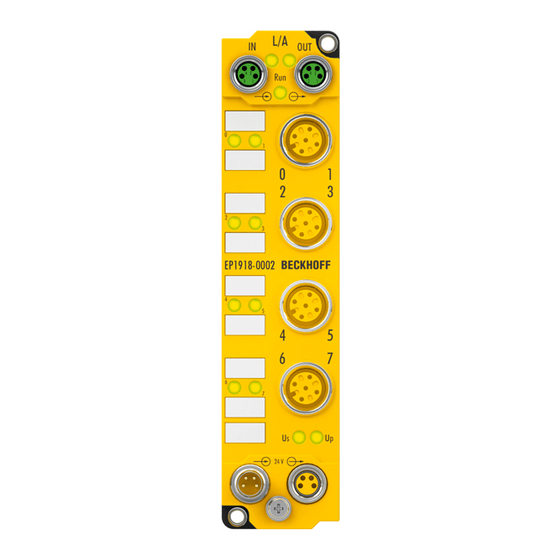
Product description Product description EP1918-0002 The EP1918-0002 TwinSAFE EtherCAT Box is a digital EtherCAT Box for sensors with potential-free contacts for 24 V . It has eight fail-safe inputs. The EP1918-0002 meets the requirements of the following standards: • EN 61508:2010 (SIL 3) •... -
Page 11: Intended Use
SAFE import or externally generated automatic project creation procedures, are not covered by the certifi- cate. WARNING Commissioning test Before the EP1918-0002 can be used for the safety task, the user must carry out a commissioning test so that sensor and actuator wiring faults can be ruled out. CAUTION Follow the machinery directive! The TwinSAFE components may only be used in machines as defined in the machinery directive. -
Page 12: Technical Data
Input process image 7 bytes (via FSoE if using the default project) Output process image 6 bytes (via FSoE if using the default project) Supply voltage for the EP1918 24 V (–15% / +20%) Current consumption U 8 channels occupied: typically 100 mA (wired with 8 potential-free contacts) 0 channels occupied: typically 91 mA... -
Page 13: Safety Parameters
Special proof tests throughout the service life of the EtherCAT Box are not required. Classification according to EN 61508-2:2010 (see chapter 7.4.4.1.2 and 7.4.4.1.3) The EP1918-0002 TwinSAFE EtherCAT Box can be used for fail-safe applications within the meaning of IEC 61508:2010 up to SIL3 and EN ISO 13849-1:2015 up to PL e (Cat. 4). -
Page 14: Safe Inputs
Safe inputs in Cat.4 / PL e If two safe input channels are to be used in a category 4 structure that are not on one M12 connector, please make sure to combine always an even and an odd channel number. Version: 1.1.0 EP1918... -
Page 15: Dimensions
Product description Dimensions Fig. 3: EP1918-0002 - Dimensions The TwinSAFE EtherCAT Box has the following dimensions. Width 30.0 mm Height 126.0 mm Depth 26.5 mm When fully wired, the connected cables increase the total depth of the module. EP1918 Version: 1.1.0... -
Page 16: Operation
• Note when mounting that the overall height is increased further by the fieldbus connections. 4.2.2 Connection 4.2.2.1 Nut torque for connectors M8 connector We recommend fastening the M8 connector with a torque of 0.4 Nm. A max. torque of 0.5 Nm is also permissible if using a torque screwdriver (Beckhoff article ZB8800). Version: 1.1.0 EP1918... -
Page 17: Fig. 4 Ethercat Box With M8 Plug Connectors
We recommend fastening the 7/8" plug connectors with a torque of 1.5 Nm. Fig. 6: 7/8" plug connectors Torque wrench Fig. 7: Torque wrench ZB8801 NOTE Ensure the proper torque is used Use torque wrenches available from Beckhoff to tighten the connectors (see accessories)! EP1918 Version: 1.1.0... -
Page 18: Fig. 8 Ethercat Connection 30 Mm Housing M8
EtherCAT/Ethernet infrastructure", which is available for download from www.Beck- hoff.de. EtherCAT uses four cable wires for signal transmission. Due to automatic cable detection (auto-crossing) symmetric (1:1) or cross-over cables can be used between EtherCAT devices from BECKHOFF. Version: 1.1.0 EP1918... - Page 19 General information for connecting the functional earth The earth connection of the EP1918 (see figure: EP1918 - power connection and FE) and the grounding sleeves in the fastening holes for the M3 screws for fixing the EtherCAT Box are internally connected. The earth connection is capacitively connected to Us, Up and the shield of the EtherCAT connection.
- Page 20 EtherCAT Box to EtherCAT Box in a simple manner. CAUTION Note the maximum current! Also ensure when forwarding the supply voltages Us and Up that the maximum permissible current of 4 A for each contact of the M8 plug connector is not exceeded! Version: 1.1.0 EP1918...
-
Page 21: Fig. 9 Ep1918 Pin Configuration - Inputs
Operation 4.2.2.5 Signal connection for inputs The EP1918 has 8 safe inputs. Fig. 9: EP1918 pin configuration - inputs Fig. 10: PinOut default setting PinOut alternative 2 PinOut alternative 1 (parameter input power mode = power mode B) (parameter input power mode = power mode A) EP1918 Version: 1.1.0... - Page 22 Alternatively, a safe sensor can be supplied with 24 V , instead of the clock outputs for potential-free con- tacts. The polarity of pins 1 and 3 can be parameterized. Detection of cross-circuits or external feeds must take place via the connected safe sensor. Version: 1.1.0 EP1918...
-
Page 23: Ep1918 Temperature Measurement
EtherCAT Box. 4.2.3 EP1918 temperature measurement The temperature measurement of the TwinSAFE EtherCAT Box consists of a single EtherCAT Box that is wired with corresponding supply and communication cables. The inputs and/or outputs of the EtherCAT Box are switched on for the test. -
Page 24: Signal Cables
4.2.4 Signal cables Permitted cable length Fig. 12: EP1918 cable length When connecting a single switching contact via a dedicated continuous cable (or via a sheathed cable), the maximum permitted cable length is 100 m if a sensor test is active. The use of contact points, connectors or additional switching contacts in the cabling reduces the maximum propagation. -
Page 25: Fig. 13 Cable Routing
The common routing of signals together with other clocked signals in a common cable also reduces the maximum propagation, since crosstalk of the signals can occur over long cable lengths and cause diagnostic messages. EP1918 Version: 1.1.0... -
Page 26: Ep1918 Configuration In Twincat
EL6910 documentation and the description of the function blocks under http:// www.beckhoff.de/german/download/twinsafe.htm. In order to be able to use the EP1918 again as a safe TwinSAFE I/O slave, please delete the logic, the mapping and the parameter data on the EtherCAT Box and switch the voltage off and on again. -
Page 27: Project Design Limits Of The Ep1918
Project planning TwinCAT 3.1 Build 4022.28 or later is required for the use of the internal logic functions. If the EP1918 is used as a TwinSAFE slave with the default project, at least an EL6910, EK1960 or newer logic components are required as a TwinSAFE master. -
Page 28: Address Settings On The Twinsafe Ethercat Box
4.3.5 Address settings on the TwinSAFE EtherCAT Box Fig. 16: EP1918 Rotary switches on the underside The TwinSAFE address of the Box must be set using the three rotary switches on the underside of the TwinSAFE-EP Box. TwinSAFE addresses between 1 and 4095 are available. -
Page 29: Alias Devices
The alias devices are created in the safety project when the dialog is closed via OK. Alternatively, the user can create the alias devices individually. To this end select Add and New item from the context menu, followed by the required device. EP1918 Version: 1.1.0... -
Page 30: Fig. 19 Creating Alias Devices By The User
Operation Fig. 19: Creating alias devices by the user Version: 1.1.0 EP1918... -
Page 31: Parameters Of The Ep1918
After creating the alias device, it can be parameterized according to the user specifications. The FSoE address is set under the Linking tab, and the link to the physical device is created. Fig. 20: Linking tab of the EP1918 Name Description... -
Page 32: Fig. 21 Connection Tab Of The Ep1918
Operation Under the Connection tab you can make further settings, e.g. the mapping of the info data or the behavior in case of a module error. Fig. 21: Connection tab of the EP1918 Name Description Conn. no. Connection number (issued by the system) Conn. -
Page 33: Fig. 22 Ep1918 Parameters
Operation The Safety Parameters tab contains the parameters of the EP1918 to be set. The inputs are parameterized via the objects 0x8000 etc. Fig. 22: EP1918 Parameters Index Name Default value/ Description unit 8000:01 ModuloDiagTestPulse 0x00 / integer Modulo value for the frequency of generating a test pulse. -
Page 34: Process Image Of The Ep1918
Process image of the EP1918 The process image of EP1918 consists of 7 bytes of input data and 6 bytes of output data. The 7-byte telegram contains 2 bytes of safe data, while the 6-byte telegram contains 1 byte of safe data. -
Page 35: Twinsafe Reaction Times
The typical response time is based on the following formula: ReactionTime Sensor Input Comm Logic Comm Output Actuator with ReactionTime Worst case response time The worst-case response time is the maximum time required for switching off the actuator in the event of an error. EP1918 Version: 1.1.0... -
Page 36: Fig. 25 Worst Case Response Time
This fault is detected at the output once the watchdog time has elapsed, resulting in shutdown. This results in the following formula for the worst-case response time: ReactionTime Comm Comm Actuator with ReactionTime 2 *15 Version: 1.1.0 EP1918... -
Page 37: Diagnosis
ACT: Communication with the following EtherCAT module Status of the EtherCAT module is Init flashes quickly Status of the EtherCAT module is pre-operational flashes slowly Status of the EtherCAT module is safe-operational Status of the EtherCAT module is operational EP1918 Version: 1.1.0... -
Page 38: Status Leds
Operation 4.5.2 Status LEDs Fig. 27: EP1918-0002 Status LED Display Meaning Input 1 is connected and logical 1 Input 1 is not connected and logical 0 Input 2 is connected and logical 1 Input 2 is not connected and logical 0... -
Page 39: Diagnostic Leds
Operation 4.5.3 Diagnostic LEDs Fig. 28: EP1918 - Diagnostic LEDs LED displays flashes flickering Dia1 Environment variables, Environment variables, (green) operating voltage and operating voltage and internal tests are in the valid internal tests are outside range the valid range • If Dia2 flashes, a logic •... -
Page 40: Flash Code Display
Vendor data CRC C2 CRC of the vendor data on µC2 Diagnostics history Any errors, which occur during operation of the TwinSAFE component, such as overtemperature or undervoltage, are entered in the diagnostics history with a corresponding timestamp. Version: 1.1.0 EP1918... -
Page 41: Fig. 29 Diagnostic Object - Fslogic Status (F100Hex) In The Process Image Of The Twinsafe Com- Ponent
This CoE object is additionally copied into the cyclic process image of the TwinSAFE component. From there, this information can be directly linked into the PLC. Fig. 29: Diagnostic object - FSLOGIC Status (F100 ) in the process image of the TwinSAFE component EP1918 Version: 1.1.0... -
Page 42: Cycle Time Of The Safety Project
Errors within the logic, the function blocks, the connections or the component itself are stored with a corresponding time stamp. Fig. 30: Diag history Use the Advanced… button to open the advanced settings. Here, the user can customize the behavior of the diag history. Version: 1.1.0 EP1918... -
Page 43: Diagnosis History
Both the control entries and the history itself can be found in the CoE object 0x10F3. The entry Newest Message (0x10F3:02) contains the subindex of 0x10F3, which contains the latest diagnostic message, e.g. 0x06 for diagnostic message 1. EP1918 Version: 1.1.0... - Page 44 If the bit = 1, the time stamp contained in the message is the local time stamp of the TwinSAFE device. The age of the diagnosis message can be deduced by calculation with the current time stamp from the CoE object 0x10F8. Bit 5…7 reserved Bit 8…15 Number of parameters in this diagnosis message Version: 1.1.0 EP1918...
-
Page 45: Fig. 32 Esi/Xml Message Text
The sending of emergency messages to the EtherCAT master is activated by adding the CoE object 0x10F3:05 to the startup list (Transition IP, value 0x0001). If new diagnostic messages arrive, they are entered in object 0x10F3 and additionally sent by emergency to the EtherCAT master. Fig. 33: Startup list EP1918 Version: 1.1.0... -
Page 46: Maintenance
YY: Year of manufacture Year: 2018 SW: Software version Software version: 01 HW: Hardware version Hardware version: 02 Serial number (S. no.) In addition, the TwinSAFE EtherCAT Boxes have a unique serial number (S. no.). Fig. 34: EP1918 serial number Version: 1.1.0 EP1918... -
Page 47: Decommissioning
• Housing parts (WELLAMID) can be sent for plastic recycling • Sealing compound: Polyurethane resin • Metal parts can be sent for metal recycling. • Electronic parts such as disk drives and circuit boards must be disposed of in accordance with national electronics scrap regulations. EP1918 Version: 1.1.0... -
Page 48: Firmware Update Of Twinsafe Products
TwinSAFE component is deleted and replaced by a new version. The latest firmware can be downloaded from the Beckhoff website. The versions are available in an encrypted form and can only be loaded onto the matching TwinSAFE product. An incorrect firmware file is rejected by the respective TwinSAFE product. -
Page 49: Fig. 35 Firmware Update Of Twinsafe Products - Part 1
(7) together; for individual components, select only these. Subsequently, click with the right mouse button inside the selected area and select the command "Firmware Update..." (8) in the command overview. EP1918 Version: 1.1.0... -
Page 50: Fig. 36 Firmware Update Of Twinsafe Products - Part 2
After successful completion you must click OK (12) in the concluding "Function Succeeded" window. You can then switch the system back to Run mode and use the TwinSAFE system. Fig. 37: Firmware update of TwinSAFE products - Part 3 Version: 1.1.0 EP1918... -
Page 51: Appendix
Protection against the effects of temporary immersion. The quantity of water being able to penetrate if the housing is submerged in water for 30 minutes at a depth of 1 m must not have any adverse effects. *) These protection classes only define protection against water, not against other liquids. EP1918 Version: 1.1.0... -
Page 52: Support And Service
Beckhoff's branch offices and representatives Please contact your Beckhoff branch office or representative for local support and service on Beckhoff products! The addresses of Beckhoff's branch offices and representatives round the world can be found on her internet pages: http://www.beckhoff.com You will also find further documentation for Beckhoff components there. -
Page 53: Certificates
Appendix Certificates EP1918 Version: 1.1.0... - Page 54 Table of figures Fig. 1 EtherCAT Box modules extend the EtherCAT system with IP67 protection........ Fig. 2 EP1918-0002 - TwinSAFE EtherCAT Box with 8 fail-safe inputs ..........Fig. 3 EP1918-0002 - Dimensions......................Fig. 4 EtherCAT Box with M8 plug connectors ..................
- Page 56 More Information: www.beckhoff.com/EP1918 Beckhoff Automation GmbH & Co. KG Hülshorstweg 20 33415 Verl Germany Phone: +49 5246 9630 info@beckhoff.com www.beckhoff.com...
Need help?
Do you have a question about the EP1918 and is the answer not in the manual?
Questions and answers