Sign In
Upload
Download
Table of Contents
Contents
Add to my manuals
Delete from my manuals
Share
URL of this page:
HTML Link:
Bookmark this page
Add
Manual will be automatically added to "My Manuals"
Print this page
×
Bookmark added
×
Added to my manuals
Manuals
Brands
Beckhoff Manuals
Industrial Electrical
KL27 2 Series
Documentation
Beckhoff KL27 2 Series Documentation
Solid state and triac terminals
Hide thumbs
1
2
3
4
5
6
7
8
9
10
11
12
13
14
15
16
17
18
19
20
21
22
23
24
25
26
27
28
29
30
31
32
33
page
of
33
Go
/
33
Contents
Table of Contents
Bookmarks
Table of Contents
Table of Contents
1 Foreword
Notes on the Documentation
Safety Instructions
Documentation Issue Status
2 Product Overview
KL2701 and KL2702 - Solid State Terminals
KL2701 - Introduction
Fig. 1 KL2701 - 1-Channel Solid State Load Relay up to 230 VAC/DC, 3 a
KL2701 - Technical Data
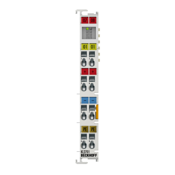
KL2701 - Connection and LED Displays
Fig. 2 KL2701 Leds and Connection
KL2702 - Introduction
Fig. 3 KL2702 - 2-Channel Solid State Load Relay up to 230 VAC/DC
KL2702 - Technical Data
KL2702 - Connection and LED Displays
Fig. 4 KL2702 - Connection and LED Displays
KL2712, KL2722 and KL2732 - Triac Terminals
KL2712 - Introduction
Fig. 5 KL2712 - 2-Channel Triac Output Terminal, 12
KL2722 - Introduction
Fig. 6 KL2722 - 2-Channel Triac Output Terminal, 12
KL2732 - Introduction
Fig. 7 KL2732 - 2-Channel Triac Output Terminal, 12
Technical Data
KL2712, KL2722 - Connection and LED Displays
Fig. 8 KL2712 and KL2722 - Connection and LED Displays
KL2732 - Connection and LED Displays
Fig. 9 KL2732 - Connection and LED Displays
3 Mounting and Wiring
Installation on Mounting Rails
Fig. 10 Attaching on Mounting Rail
Fig. 11 Disassembling of Terminal
Connection System
Fig. 12 Power Contact on Left Side
Fig. 13 Standard Wiring
Fig. 14 Pluggable Wiring
Fig. 15 High Density Terminals
Fig. 16 Mounting a Cable on a Terminal Connection
ATEX - Special Conditions (Standard Temperature Range)
Continuative Documentation about Explosion Protection
4 Twincat
Programming
5 Appendix
Support and Service
Table of Figures
Advertisement
Quick Links
Download this manual
Documentation | EN
KL2701, KS2701 und KL27x2,
KS27x2
Solid state and triac terminals
2020-10-20 | Version: 1.0.0
Table of
Contents
Previous
Page
Next
Page
1
2
3
4
5
Advertisement
Chapters
Table of Contents
3
Table of Figures
31
Table of Contents
Need help?
Do you have a question about the KL27 2 Series and is the answer not in the manual?
Ask a question
Questions and answers
Related Manuals for Beckhoff KL27 2 Series
Industrial Electrical Beckhoff KS2784 Manual
Four channel bus terminals with digital switching outputs, solid state (26 pages)
Industrial Electrical Beckhoff KL2784 Documentation
Four channel digital output terminals with mosfet transistors (23 pages)
Industrial Electrical Beckhoff KL2692 Documentation
Watchdog terminal (34 pages)
Industrial Electrical Beckhoff KS2692 Documentation
Watchdog terminal (39 pages)
Industrial Electrical Beckhoff KL2819 Documentation
Hd bus terminal, 16-channel digital output 24 v dc, with diagnostics (31 pages)
Industrial Electrical Beckhoff KL6031 Series Documentation
Serial interface terminals (48 pages)
Industrial Electrical Beckhoff KL2701 Series Documentation
Solid state and triac terminals (33 pages)
Industrial Electrical Beckhoff KL2442 Documentation
2 channel digital output terminal, 24 v dc, 2 x 4 a / 1 x 8 a (23 pages)
Industrial Electrical Beckhoff KL9570 Documentation
Buffer capacitor terminal (21 pages)
Industrial Electrical Beckhoff KL6821 Documentation
Dali-2 multimaster terminal with integrated power supply (41 pages)
Industrial Electrical Beckhoff TwinSAFE logic FB Documentation
Twincat function blocks for twinsafe logic components (217 pages)
Industrial Electrical Beckhoff C9900-G05 Series Manual
Compact push-button extension (38 pages)
Industrial Electrical Beckhoff EP1918 Operating Instruction
Twinsafe ethercat box with 8 fail-safe inputs (56 pages)
Industrial Electrical Beckhoff BK9053 Documentation
Bus coupler for profinet (49 pages)
Industrial Electrical Beckhoff eXtended Transport System Operating Instructions Manual
(114 pages)
Industrial Electrical Beckhoff EK3100 Documentation
Profibus bus coupler for ethercat terminals (58 pages)
This manual is also suitable for:
Ks27 2 series
Kl2701 series
Ks2701 series
Kl2701-0000
Ks2701-0000
Kl2702-0000
...
Show all
Ks2702-0000
Kl2702-0020
Kl2702-0002
Kl2712-0000
Ks2712-0000
Kl2722-0000
Ks2722-0000
Kl2732-0000
Ks2732-0000
Table of Contents
Print
Rename the bookmark
Delete bookmark?
Delete from my manuals?
Login
Sign In
OR
Sign in with Facebook
Sign in with Google
Upload manual
Upload from disk
Upload from URL


Need help?
Do you have a question about the KL27 2 Series and is the answer not in the manual?
Questions and answers