
Related Manuals for Beckhoff KL6821


Summary of Contents for Beckhoff KL6821
- Page 1 Documentation | EN KL6821 DALI-2 Multimaster Terminal with integrated Power Supply 2023-06-27 | Version: 1.0.0...
-
Page 3: Table Of Contents
3.4.4 Connection ........................ 29 LED displays ........................... 30 4 KS2000 Configuration Software ...................... 32 KS2000 - Introduction ........................ 32 KL6821 configuration ........................ 34 KS2000 Settings .......................... 35 5 Programming ............................ 37 TwinCAT libraries .......................... 37 6 Appendix .............................. 38 Support and Service........................ 38 KL6821 Version: 1.0.0... - Page 4 Table of contents Version: 1.0.0 KL6821...
-
Page 5: Foreword
, XTS and XPlanar are registered trademarks of and licensed by Beckhoff Automation GmbH. Other designations used in this publication may be trademarks whose use by third parties for their own purposes could violate the rights of the owners. Patent Pending... -
Page 6: Safety Instructions
All the components are supplied in particular hardware and software configurations appropriate for the application. Modifications to hardware or software configurations other than those described in the documentation are not permitted, and nullify the liability of Beckhoff Automation GmbH & Co. KG. Personnel qualification This description is only intended for trained specialists in control, automation and drive engineering who are familiar with the applicable national standards. -
Page 7: Documentation Issue Status
The firmware and hardware versions (delivery state) of the terminal can be found in the serial number printed on the side. The KL6821 from firmware 08 and hardware 08 is DALI-2 certified and can be clearly identified by the DALI-2 logo on the terminal side. -
Page 8: Product Overview
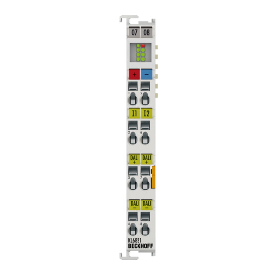
Introduction Fig. 1: KL6821 The KL6821 allows the connection of up to 64 DALI control gears and up to 63 DALI-2 control devices. The KS2000 configuration software facilitates parameterization via a PC. The KL6821 contains an integrated DALI-2 power supply that can be switched off with electrically isolated output voltage. No further components are required for operation of the DALI devices. -
Page 9: Technical Data
Product overview Technical data Technical data KL6821 Data transfer channels DALI slaves / groups max. 64 DALI control gears and max. 63 DALI-2 control devices / max. 16 groups Bit width in the K-bus I/O 4 x 8 bit user data, 1 x 16 bit control/status... -
Page 10: Dali
(IEC 62386) allows the manufacturers of lighting components to implement complex lighting tasks easily and conveniently. The KL6811 (DALI version-1/DSI) and KL6821/EL6821 (DALI-2) Bus Terminals are integrated into the bus terminal system and are therefore fieldbus-independent. The DALI data is forwarded to the DALI devices via the respective bus coupler. -
Page 11: Communication
Product overview Up to 64 DALI control gears and up to 64 DALI control devices can be connected to the KL6821 per DALI line. The KL6821 represents the DALI controller. One such device exists for each DALI line. Up to 64 control gears, which have to be DALI/DSI devices, can be connected to the KL6811. -
Page 12: Priorities
Most function blocks referred to in chapter Part 102 (control gears) have the input eCommandPriority. This input is used to specify the priority with which the DALI commands are to be sent via the KL6821. Events also have a priority (event priority), which is represented by the data type E_DALIEventPriority. Event priorities can have 4 values in the range Low (DALI priority 5) to Middle high (DALI priority 2). -
Page 13: Bus Timing
Priorities are always important in situations where DALI sensors (input devices) send events and DALI commands are sent in parallel via the KL6821. If no DALI sensors (input devices) are used, the priority of the DALI commands is of secondary importance, since in this case there is only one DALI master (the KL6821). - Page 14 17.0 ms + (17 x 0.833 ms) + 8.0 ms + (9 x 0.833 ms) = 46.7 ms. 16-bit telegram send-twice: 17.0 ms + (17 x 0.833 ms) + 14.1 ms + (17 x 0.833 ms) = 59.4 ms. Version: 1.0.0 KL6821...
- Page 15 If the break sequence is finished at DALI device 2, the DALI bus is not occupied by any other DALI device (point D). Therefore the recover sequence is started at DALI device 2 and then the DALI telegram is sent again directly (without settling time). KL6821 Version: 1.0.0...
- Page 16 The times in the top line (4 ms ... 80 ms) specify the cycle time of the PLC task from which the DALI commands are started. The times (2 ms ... 30 ms) in the first column specify the cycle time of the PLC task for background communication. Version: 1.0.0 KL6821...
-
Page 17: Memory Banks
Memory bank 0 is read only and contains general, vendor-specific information about the DALI control gear or DALI control device. Every certified DALI device must implement memory bank 0. Up to offset 16#1A the fields are defined by IEC 62386 as follows. KL6821 Version: 1.0.0... - Page 18 Reserved, not implemented Structure of memory bank 1: Memory bank 1 can be used by the device vendor to store further information in the DALI device. Up to offset 16#10 the fields are defined by IEC 62386 as follows. Version: 1.0.0 KL6821...
-
Page 19: Dali-2 Current
2.3.6 DALI-2 current The DALI power supply of the KL6821 has a maximum output current of 250 mA and a guaranteed DALI current of 220 mA. To ensure safe operation of the DALI bus, the connected DALI devices must never consume more than the guaranteed DALI-2 current in total. -
Page 20: Fig. 2 Dali-2 Current
Furthermore, a reserve specified in IEC 62386 (guaranteed DALI current / 1.2) should be maintained. This reserve is intended for the subsequent installation of additional devices that may be added in the course of a project. Fig. 2: DALI-2 current Version: 1.0.0 KL6821... -
Page 21: Mounting And Wiring
• Surroundings (working place, packaging and personnel) should by grounded probably, when handling with the devices. • Each assembly must be terminated at the right hand end with a KL9010 bus end terminal, to ensure the protection class and ESD protection. Fig. 3: Spring contacts of the Beckhoff I/O components KL6821 Version: 1.0.0... -
Page 22: Installation On Mounting Rails
To mount the mounting rails with a height of 7.5 mm under the terminals and couplers, you should use flat mounting connections (e.g. countersunk screws or blind rivets). Version: 1.0.0 KL6821... -
Page 23: Fig. 5 Disassembling Of Terminal
KL92xx or EL91xx, EL92xx) interrupt the power contacts and thus represent the start of a new supply rail. PE power contact The power contact labeled PE can be used as a protective earth. For safety reasons this contact mates first when plugging together, and can ground short-circuit currents of up to 125 A. KL6821 Version: 1.0.0... -
Page 24: Disposal
Products marked with a crossed-out wheeled bin shall not be discarded with the normal waste stream. The device is considered as waste electrical and electronic equipment. The national regulations for the disposal of waste electrical and electronic equipment must be observed. Version: 1.0.0 KL6821... -
Page 25: Connection
Insert the new component and plug in the connector with the wiring. This reduces the installation time and eliminates the risk of wires being mixed up. The familiar dimensions of the terminal only had to be changed slightly. The new connector adds about 3 mm. The maximum height of the terminal remains unchanged. KL6821 Version: 1.0.0... -
Page 26: Fig. 9 High Density Terminals
Ultrasonically “bonded” (ultrasonically welded) conductors Ultrasonically “bonded” conductors It is also possible to connect the Standard and High Density Terminals with ultrasonically “bonded” (ultrasonically welded) conductors. In this case, please note the tables concerning the wire-size width [} 27]! Version: 1.0.0 KL6821... -
Page 27: Wiring
The cables are released, as usual, using the contact release with the aid of a screwdriver. See the following table for the suitable wire size width. KL6821 Version: 1.0.0... -
Page 28: Shielding
0.14 ... 0.75 mm Wire size width (ultrasonically “bonded" conductors) only 1.5 mm (see notice [} 26]) Wire stripping length 8 ... 9 mm 3.4.3 Shielding Shielding Encoder, analog sensors and actuators should always be connected with shielded, twisted paired wires. Version: 1.0.0 KL6821... -
Page 29: Connection
WARNING Risk of injury through electric shock and damage to the device! Bring the bus terminal system into a safe, de-energized state before starting mounting, disassembly or wiring of the bus terminals! Fig. 11: KL6821 - Connection Connection Terminal Connection for point +24 V DALI + 1... -
Page 30: Led Displays
Contacts for the DALI-2 bus line (DALI+, DALI-) and mains voltage If the contacts for the DALI-2 bus line (DALI+, DALI-) are accidentally connected to 230 V mains voltage, the KL6821 is not destroyed, but switches off. Cable lengths in DALI mode The DALI bus can be configured in a line or star topology, or in a mix of the two. - Page 31 DI 1 is switched off DI 1 is switched on or was active and has not yet been acknowledged Input 2 green DI 2 is switched off DI 2 is switched on or was active and has not yet been acknowledged KL6821 Version: 1.0.0...
-
Page 32: Ks2000 Configuration Software
Fieldbus Box modules with the aid of which settings can be modified easily. Alternatively, you have full access to all internal registers of the bus couplers and intelligent terminals. Refer to the register description for the meanings of the registers. Version: 1.0.0 KL6821... - Page 33 • Process values can be specified in the output image for commissioning of the output modules. All possibilities in the online mode can be used in parallel with the actual fieldbus mode of the terminal station. The fieldbus protocol always has the higher priority in this case. KL6821 Version: 1.0.0...
-
Page 34: Kl6821 Configuration
In the example shown, this is • a BK9000 Bus Coupler for Ethernet • a KL1xx2 digital input terminal • a KL6821 DALI-2 master terminal • a KL9010 bus end terminal Fig. 14: Display of the fieldbus station in KS2000 The left window of the KS2000 shows the terminals of the fieldbus station in a tree structure. -
Page 35: Ks2000 Settings
All parameters of the KL6821 can also be set via the KS2000. This makes it possible, for example, to define the DALI commands that are sent when the digital inputs on the KL6821 are actuated. - Page 36 KS2000 Configuration Software Overview of the most important functions in the KS2000 for the KL6821: • Find DALI devices • Addressing the DALI devices, including adapting the short addresses • Scene and group assignment of the DALI control gears • Configuration of the DALI control gears, including the parameters for the different device types •...
-
Page 37: Programming
Programming Programming The KL6821 is programmed exclusively via function blocks of the PLC libraries. The libraries are available for TwinCAT 2 as well as for TwinCAT 3. TwinCAT libraries See software documentation in the Beckhoff Information System. TwinCAT 2: TwinCAT 2 | PLC Library: TcDALIV2... -
Page 38: Appendix
Please contact your Beckhoff branch office or representative for local support and service on Beckhoff products! The addresses of Beckhoff's branch offices and representatives round the world can be found on her internet pages: www.beckhoff.com You will also find further documentation for Beckhoff components there. - Page 39 Fig. 11 KL6821 - Connection ........................Fig. 12 KL6821 LEDs ..........................Fig. 13 KS2000 configuration software ....................Fig. 14 Display of the fieldbus station in KS2000..................Fig. 15 KS2000 tree branches for channel 1 of the KL6821 ..............KL6821 Version: 1.0.0...
- Page 41 More Information: www.beckhoff.com/KL6821 Beckhoff Automation GmbH & Co. KG Hülshorstweg 20 33415 Verl Germany Phone: +49 5246 9630 info@beckhoff.com www.beckhoff.com...
Need help?
Do you have a question about the KL6821 and is the answer not in the manual?
Questions and answers