
Related Manuals for Tektronix Keithley SourceMeter 2450


Summary of Contents for Tektronix Keithley SourceMeter 2450
- Page 1 tek.com/keithley Model 2450 SourceMeter Instrument ® User’s Manual 2450-900-01 Rev. E / August 2019 *P2450-900-01E* 2450-900-01E...
- Page 2 Model 2450 ® SourceMeter Instrument User's Manual...
- Page 3 © 2019, Keithley Instruments, LLC Cleveland, Ohio, U.S.A. All rights reserved. Any unauthorized reproduction, photocopy, or use of the information herein, in whole or in part, without the prior written approval of Keithley Instruments, LLC, is strictly prohibited. These are the original instructions in English. ®...
- Page 4 Safety precautions The following safety precautions should be observed before using this product and any associated instrumentation. Although some instruments and accessories would normally be used with nonhazardous voltages, there are situations where hazardous conditions may be present. This product is intended for use by personnel who recognize shock hazards and are familiar with the safety precautions required to avoid possible injury.
- Page 5 For safety, instruments and accessories must be used in accordance with the operating instructions. If the instruments or accessories are used in a manner not specified in the operating instructions, the protection provided by the equipment may be impaired. Do not exceed the maximum signal levels of the instruments and accessories. Maximum signal levels are defined in the specifications and operating information and shown on the instrument panels, test fixture panels, and switching cards.
-
Page 6: Table Of Contents
Table of contents Introduction ........................ 1-1 Welcome ..........................1-1 Introduction to this manual ....................1-1 Extended warranty ....................... 1-2 Contact information ......................1-2 Available documentation ...................... 1-2 Organization of manual sections ..................1-3 Applications .......................... 1-3 Front-panel overview ....................2-1 Power the instrument on or off ..................... - Page 7 Table of contents Model 2450 SourceMeter® Instrument User's Manual Making basic front-panel measurements ..............4-1 Introduction .......................... 4-1 Equipment required for this application ................4-2 Device connections ......................4-2 Make front-panel measurements ..................4-3 How to make front-panel measurements .................. 4-3 Measuring low-resistance devices ................
- Page 8 Model 2450 SourceMeter® Instrument User's Manual Table of contents Device connections ......................7-5 Remote control of FET testing using SCPI commands ............7-6 Set up the application using SCPI commands with the trigger model ........7-6 Set up the application using SCPI commands in a linear sweep ..........7-9 Remote control of FET testing using TSP commands ............
-
Page 9: Introduction
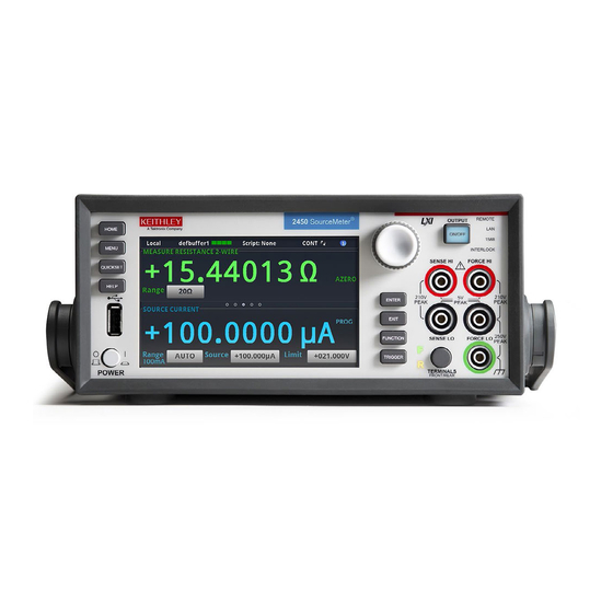
Section 1 Introduction In this section: Welcome .................. 1-1 Introduction to this manual ............1-1 Extended warranty ..............1-2 Contact information ..............1-2 Available documentation ............1-2 Organization of manual sections ..........1-3 Applications ................1-3 Welcome ® Thank you for choosing a Keithley Instruments product. The 2450 SourceMeter Instrument is a precise, low-noise instrument that combines a stable DC power supply, current source, electronic load, and a high-impedance multimeter. -
Page 10: Extended Warranty
Section 1: Introduction Model 2450 SourceMeter® Instrument User's Manual Extended warranty Additional years of warranty coverage are available on many products. These valuable contracts protect you from unbudgeted service expenses and provide additional years of protection at a fraction of the price of a repair. Extended warranties are available on new and existing products. Contact your local Keithley Instruments office, sales partner, or distributor for details. -
Page 11: Organization Of Manual Sections
Model 2450 SourceMeter® Instrument User's Manual Section 1: Introduction Organization of manual sections This manual is organized into the following sections: • Front-panel overview (on page 2-1): Describes the basics of using the front-panel interface. • Using a remote interface (on page 3-1): Describes the basics of remote communications and using the instrument web interface. - Page 12 Section 2 Front-panel overview In this section: Power the instrument on or off ..........2-1 Front-panel overview ..............2-2 Turn the 2450 output on or off ..........2-4 Touchscreen display ..............2-5 Store measurements on a USB flash drive ......2-10 Save screen captures to a USB flash drive ......
-
Page 13: Front-Panel Overview
Section 2: Front-panel overview Model 2450 SourceMeter® Instrument User's Manual To connect the power cord: 1. Make sure that the front-panel POWER switch is in the off (O) position. 2. Connect the female end of the supplied power cord to the AC receptacle on the rear panel. 3. -
Page 14: Front-Panel Overview
Model 2450 SourceMeter® Instrument User's Manual Section 2: Front-panel overview Control Graphic Description POWER switch Turns the instrument on or off. To turn the instrument on, press the power switch so that it is in the on position (|). To turn it off, press the power switch so that it is in the off position (O). -
Page 15: Turn The 2450 Output On Or Off
Section 2: Front-panel overview Model 2450 SourceMeter® Instrument User's Manual Control Graphic Description SENSE terminals Use the SENSE HI and SENSE LO terminal connections to measure voltage at the device under test (DUT). When you use sense leads, measurement of the voltage drop across the force leads is eliminated. -
Page 16: Touchscreen Display
Model 2450 SourceMeter® Instrument User's Manual Section 2: Front-panel overview Using the front panel: Press the OUTPUT ON/OFF switch. The instrument is in the output-on state when the switch is illuminated. The instrument is in the output-off state when the switch is not illuminated. Using SCPI commands: To turn the output on, send the command: :OUTPut:STATe ON... -
Page 17: Scroll Bars
Section 2: Front-panel overview Model 2450 SourceMeter® Instrument User's Manual Scroll bars Some of the interactive screens have additional options that are only visible when you scroll down the screen. A scroll indicator on the right side of the touchscreen identifies these screens. Swipe the screen up or down to view the additional options. - Page 18 Model 2450 SourceMeter® Instrument User's Manual Section 2: Front-panel overview Swipe screen heading bar The heading bar of the swipe screen contains the following options. Figure 4: Swipe screens, maximized and minimized Screen element Description Minimize indicator You can swipe down to minimize the swipe screens. Swipe screen indicator Each circle represents one swipe screen.
- Page 19 Section 2: Front-panel overview Model 2450 SourceMeter® Instrument User's Manual SOURCE swipe screen The SOURCE swipe screen shows the present value of the source and the set values for source, source range, and source limit. You can change the set values from the front panel by selecting the buttons on this screen.
- Page 20 Model 2450 SourceMeter® Instrument User's Manual Section 2: Front-panel overview STATISTICS swipe screen The STATISTICS swipe screen contains information about the readings in the active reading buffer. When the reading buffer is configured to fill continuously and overwrite old data with new data, the buffer statistics include the data that was overwritten.
-
Page 21: Menu Overview
Section 2: Front-panel overview Model 2450 SourceMeter® Instrument User's Manual Menu overview To access the main menu, press the MENU key on the 2450 front panel. The figure below shows the organization of the main menu. Figure 10: 2450 main menu The main menu includes submenus that are labeled in green across the top of the display. -
Page 22: Save Screen Captures To A Usb Flash Drive
Model 2450 SourceMeter® Instrument User's Manual Section 2: Front-panel overview Save screen captures to a USB flash drive You can save a screen capture of the front-panel display to a graphic file on a USB flash drive. The instrument saves the graphic file in PNG file format. To save a screen capture: 1. -
Page 23: Using A Remote Interface
Section 3 Using a remote interface In this section: Remote communications interfaces ......... 3-1 Supported remote interfaces ............ 3-1 GPIB communications .............. 3-2 LAN communications ............... 3-4 USB communications ............... 3-7 Using the web interface ............3-12 Determine the command set to use ........3-15 Remote communications interfaces You can choose from one of several communication interfaces to send commands to and receive responses from the 2450. -
Page 24: Gpib Communications
Section 3: Using a remote interface Model 2450 SourceMeter® Instrument User's Manual GPIB communications The 2450 GPIB interface is IEEE Std 488.1 compliant and supports IEEE Std 488.2 common commands and status model topology. You can have up to 15 devices connected to a GPIB interface, including the controller. The maximum cable length is the lesser of either: •... -
Page 25: Set The Gpib Address
Model 2450 SourceMeter® Instrument User's Manual Section 3: Using a remote interface To allow many parallel connections to one instrument, stack the connectors. Each connector has two screws on it to ensure that connections remain secure. The figure below shows a typical connection diagram for a test system with multiple instruments. -
Page 26: Lan Communications
Section 3: Using a remote interface Model 2450 SourceMeter® Instrument User's Manual The instrument saves the address in nonvolatile memory. It does not change when you send a reset command or when you turn the power off and on again. To set the GPIB address from the front panel: 1. -
Page 27: Set Up Lan Communications On The Instrument
Model 2450 SourceMeter® Instrument User's Manual Section 3: Using a remote interface Set up LAN communications on the instrument This section describes how to set up manual or automatic LAN communications on the instrument. Check communication settings Before setting up the LAN configuration, you can check the communication settings on the instrument without making any changes. -
Page 28: Set Up Lan Communications On The Computer
Section 3: Using a remote interface Model 2450 SourceMeter® Instrument User's Manual Set up manual LAN configuration If necessary, you can set the IP address on the instrument manually. You can also enable or disable the DNS settings and assign a host name to the DNS server. Contact your corporate information technology (IT) department to secure a valid IP address for the instrument when placing the instrument on a corporate network. -
Page 29: Usb Communications
Model 2450 SourceMeter® Instrument User's Manual Section 3: Using a remote interface Verify the LAN connection on the 2450 Make sure that your 2450 is connected to the network by confirming that your instrument was assigned an IP address. To verify the LAN connection: 1. -
Page 30: Connect A Computer To The 2450 Using Usb
Section 3: Using a remote interface Model 2450 SourceMeter® Instrument User's Manual Connect a computer to the 2450 using USB To communicate from a computer to the instrument you need a USB cable with a USB Type B connector end and a USB type A connector end. You need a separate USB cable for each instrument you plan to connect to the computer at the same time using the USB interface. - Page 31 Model 2450 SourceMeter® Instrument User's Manual Section 3: Using a remote interface To use the Keithley Configuration Panel to determine the VISA resource string: 1. Click Start > Keithley Instruments > Keithley Configuration Panel. The Select Operation dialog box is displayed. Figure 13: Select Operation dialog box 2.
- Page 32 Section 3: Using a remote interface Model 2450 SourceMeter® Instrument User's Manual 4. Select USB. 5. Click Next. The Select Instrument Driver dialog box is displayed. Figure 15: Select Instrument Driver dialog box 6. Select Auto-detect Instrument Driver - Model. 7.
- Page 33 Model 2450 SourceMeter® Instrument User's Manual Section 3: Using a remote interface 9. In the Virtual Instrument Name box, enter a name that you want to use to refer to the instrument. 10. Select Finish. 11. Select Cancel to close the Wizard. 12.
-
Page 34: Using The Web Interface
Section 3: Using a remote interface Model 2450 SourceMeter® Instrument User's Manual Using the web interface The 2450 web interface allows you to make settings and control your instrument through a web page. The web page includes: • Instrument status. •... -
Page 35: Web Interface Home Page
Model 2450 SourceMeter® Instrument User's Manual Section 3: Using a remote interface You can also try restarting the computer and the instrument. To restart the instrument: 1. Turn the power to the instrument off, and then on. 2. Wait at least 60 seconds for the network configuration to be completed. To set up LAN communications: 1. -
Page 36: Identify The Instrument
Section 3: Using a remote interface Model 2450 SourceMeter® Instrument User's Manual The Home page of the instrument provides information about the instrument. It includes: • The instrument model number, manufacturer, serial number, and firmware revision number. • The TCP Raw Socket number and Telnet Port number. •... -
Page 37: Determine The Command Set To Use
Model 2450 SourceMeter® Instrument User's Manual Section 3: Using a remote interface Determine the command set to use You can control the 2450 with command sets that are based on the SCPI or Test Script Processor ® (TSP ) programming languages. You can change the command set that you use with the 2450. The remote command sets that are available include: •... - Page 38 Section 3: Using a remote interface Model 2450 SourceMeter® Instrument User's Manual To verify which command set is selected from a remote interface: Send the command: *LANG? To change to the SCPI command set from a remote interface: Send the command: *LANG SCPI Reboot the instrument.
-
Page 39: Making Basic Front-Panel Measurements
Section 4 Making basic front-panel measurements In this section: Introduction ................4-1 Equipment required for this application ........4-2 Device connections ..............4-2 Make front-panel measurements ..........4-3 Introduction You can use the 2450 to source voltage or current and make measurements from the front panel. Make sure you select functions before you make changes to other instrument settings. -
Page 40: Equipment Required For This Application
Section 4: Making basic front-panel measurements Model 2450 SourceMeter® Instrument User's Manual Equipment required for this application Equipment required for this application: • ® 2450 SourceMeter Instrument • Two insulated banana cables; you can use the set that is provided with the 2450, the Keithley Instruments Model 8608 High-Performance Clip Lead Set •... -
Page 41: Make Front-Panel Measurements
Model 2450 SourceMeter® Instrument User's Manual Section 4: Making basic front-panel measurements Make front-panel measurements For this application, you will: • Select the source and measure functions • Select the source range • Set the source value • Set the source limit •... -
Page 42: Measuring Low-Resistance Devices
Section 5 Measuring low-resistance devices In this section: Introduction ................5-1 Equipment required ..............5-1 Set up remote communications ..........5-2 Device connections ..............5-2 Low-resistance measurements ..........5-5 Introduction This application example demonstrates how to use the 2450 to measure a low-resistance device. You may need to make low-resistance measurements (<10 Ω) in a number of applications. -
Page 43: Set Up Remote Communications
Section 5: Measuring low-resistance devices Model 2450 SourceMeter® Instrument User's Manual Set up remote communications You can run this application from the front panel or any of the supported communication interfaces for the instrument (GPIB, USB, or ethernet). The following figure shows the rear-panel connection locations for the remote communication interfaces. - Page 44 Model 2450 SourceMeter® Instrument User's Manual Section 5: Measuring low-resistance devices Hazardous voltages may be present on all output and guard terminals. To prevent electrical shock that could cause injury or death, never make or break connections to the 2450 while the output is on.
- Page 45 Section 5: Measuring low-resistance devices Model 2450 SourceMeter® Instrument User's Manual Turn the power to the instrument off before attaching connections to the 2450. When you connect the leads to the device under test (DUT), notice that the FORCE LO and SENSE LO connections are attached to one of the DUT leads.
-
Page 46: Low-Resistance Measurements
Model 2450 SourceMeter® Instrument User's Manual Section 5: Measuring low-resistance devices Low-resistance measurements This application demonstrates how to use the 2450 to measure a low-resistance device. You can measure from the front panel or over the remote interface using SCPI code or TSP code. For this application, you will: •... -
Page 47: View The Measurements On The Front-Panel Graph Swipe Screen
Section 5: Measuring low-resistance devices Model 2450 SourceMeter® Instrument User's Manual 14. Select Continuous Measurement to start making measurements. The instrument displays the measurements in the MEASURE VOLTAGE area of the home screen. Figure 24: Measurement Method indicator with Continuous Measurement selected 15. -
Page 48: View The Buffer Statistics On The Front Panel
Model 2450 SourceMeter® Instrument User's Manual Section 5: Measuring low-resistance devices View the buffer statistics on the front panel You can view the measurement statistics on the 2450 front-panel STATISTICS swipe screen, including: • Peak-to-peak value • Minimum, maximum, and average reading values •... -
Page 49: Set Up The Low-Resistance Application Using Tsp Commands
Section 5: Measuring low-resistance devices Model 2450 SourceMeter® Instrument User's Manual Set up the low-resistance application using TSP commands The following TSP code is designed to be run from Keithley Instruments Test Script Builder (TSB). TSB is a software tool that is available from tek.com/keithley. You can install and use TSB to write code and develop scripts for TSP-enabled instruments. -
Page 50: Leakage Current And Insulation Resistance
Section 6 Leakage current and insulation resistance In this section: Introduction ................6-1 Equipment required ..............6-2 Set up remote communications ..........6-2 Device connections ..............6-2 Measuring leakage current ............6-4 Measuring insulation resistance ..........6-10 Introduction To measure the leakage current or insulation resistance of a device, you need to apply a fixed voltage to the device and measure the resulting current. -
Page 51: Equipment Required
Section 6: Leakage current and insulation resistance Model 2450 SourceMeter® Instrument User's Manual Equipment required • ® One 2450 SourceMeter Instrument • Two triaxial cables • One capacitor for the leakage current application • One coaxial cable or other device for the insulation resistance application •... - Page 52 Model 2450 SourceMeter® Instrument User's Manual Section 6: Leakage current and insulation resistance The following figure shows schematic diagrams. One shows measuring the leakage current of a capacitor. The other shows measuring the insulator resistance between two conductors of a coaxial cable.
-
Page 53: Measuring Leakage Current
Section 6: Leakage current and insulation resistance Model 2450 SourceMeter® Instrument User's Manual Figure 30: Rear-panel connections insulation resistance test Measuring leakage current The following application demonstrates how to use the 2450 to measure the leakage current of a 1 nF capacitor by sourcing a voltage and measuring the resulting current using the front panel or over the remote interface. -
Page 54: Set Up The Leakage Current Application Using The Front Panel
Model 2450 SourceMeter® Instrument User's Manual Section 6: Leakage current and insulation resistance When you use the 2450 to measure small current values, ensure that the device under test is electrostatically shielded. If the capacitor rating is greater than 20 nF, enable the high capacitance mode for best results. -
Page 55: View The Measurements On The Front-Panel Graph
Section 6: Leakage current and insulation resistance Model 2450 SourceMeter® Instrument User's Manual View the measurements on the front-panel graph To view the leakage current measurements on the front-panel graph: 1. Press the MENU key. 2. Under Views, select Graph. 3. -
Page 56: Set Up The Leakage Current Application Using Scpi Commands
Model 2450 SourceMeter® Instrument User's Manual Section 6: Leakage current and insulation resistance Set up the leakage current application using SCPI commands The following SCPI code performs a capacitor leakage measurement by sourcing 20 V and measuring the resulting leakage current. The DurationLoop trigger model template applies the voltage for 30 seconds and makes measurements at 200 ms intervals. -
Page 57: Set Up The Leakage Current Application Using Tsp Commands
Section 6: Leakage current and insulation resistance Model 2450 SourceMeter® Instrument User's Manual Set up the leakage current application using TSP commands The following TSP code is designed to be run from Keithley Instruments Test Script Builder (TSB). TSB is a software tool that is available from tek.com/keithley. You can install and use TSB to write code and develop scripts for TSP-enabled instruments. - Page 58 Model 2450 SourceMeter® Instrument User's Manual Section 6: Leakage current and insulation resistance Send the following commands for this example application: -- Reset the instrument, which also clears the buffer. reset() -- Set up the source function. smu.source.func = smu.FUNC_DC_VOLTAGE smu.source.ilimit.level = 10e-3 smu.source.level = 20 -- Set up measure function.
-
Page 59: Measuring Insulation Resistance
Section 6: Leakage current and insulation resistance Model 2450 SourceMeter® Instrument User's Manual Measuring insulation resistance The following application demonstrates how to use the 2450 to measure insulator resistance. The application shows how to use the front-panel interface, the remote interface using the SCPI command ®... -
Page 60: Viewing The Measurements On The Front-Panel Graph
Model 2450 SourceMeter® Instrument User's Manual Section 6: Leakage current and insulation resistance 10. Press the MENU key. 11. Under Trigger, select Templates. 12. Set Templates to SimpleLoop. 13. Set Count to 10. 14. Set Delay to 0.1 seconds. 15. Press the HOME key. 16. -
Page 61: Set Up The Application Using Scpi Commands
Section 6: Leakage current and insulation resistance Model 2450 SourceMeter® Instrument User's Manual Set up the application using SCPI commands The following SCPI commands make insulation resistance measurements by sourcing 20 V and measuring the resistance. The Simple Loop trigger model template is used to make 10 measurements at 100 ms intervals. -
Page 62: Set Up The Application Using Tsp Commands
Model 2450 SourceMeter® Instrument User's Manual Section 6: Leakage current and insulation resistance Set up the application using TSP commands The following TSP code is designed to be run from Keithley Instruments Test Script Builder (TSB). TSB is a software tool that is available from tek.com/keithley. You can install and use TSB to write code and develop scripts for TSP-enabled instruments. - Page 63 Section 6: Leakage current and insulation resistance Model 2450 SourceMeter® Instrument User's Manual The graph in the following figure demonstrates what the plotted results might look like. Figure 34: Insulation resistance test results 6-14 2450-900-01 Rev. E / August 2019...
-
Page 64: Measuring I-V Characteristics Of Fets
Section 7 Measuring I-V characteristics of FETs In this section: Introduction ................7-1 Equipment required ..............7-1 Set up remote communications ..........7-2 Set up external hardware triggers ..........7-2 Device connections ..............7-5 Remote control of FET testing using SCPI commands .... 7-6 Remote control of FET testing using TSP commands .... -
Page 65: Set Up Remote Communications
Section 7: Measuring I-V characteristics of FETs Model 2450 SourceMeter® Instrument User's Manual • The cabling for external hardware triggers depends on the command set you are using: For SCPI commands, use a DB-9 male-to-male 9-pin cable to connect the digital I/O ports on the back of the 2450 instruments to each other. -
Page 66: Connections For The Scpi Command Set
Model 2450 SourceMeter® Instrument User's Manual Section 7: Measuring I-V characteristics of FETs Connections for the SCPI command set If you are using the SCPI command set, connect a DB-9 male-to-male cable between the digital I/O connectors on the back of each of the instruments, as shown in the figure below. For more detailed information about the digital I/O connector pins, see “Digital I/O”... -
Page 67: Connections For The Tsp Command Set
Section 7: Measuring I-V characteristics of FETs Model 2450 SourceMeter® Instrument User's Manual Connections for the TSP command set ® If you use the Test Script Processor (TSP ) command set for remote programming, use a RJ-45 LAN crossover cable (one is included with the 2450) to connect the TSP-Link ports on the rear panels of the 2450 instruments (see figure below). -
Page 68: Device Connections
Model 2450 SourceMeter® Instrument User's Manual Section 7: Measuring I-V characteristics of FETs Device connections To perform a drain family of curves, configure both instruments to source voltage and measure current. In this circuit, you connect the Force HI terminal of 2450 #2 to the gate of the MOSFET, and connect the Force HI terminal of 2450 #1 to the drain. -
Page 69: Remote Control Of Fet Testing Using Scpi Commands
Section 7: Measuring I-V characteristics of FETs Model 2450 SourceMeter® Instrument User's Manual For this application, connect four triaxial cables (Model 7078-TRX-10) from the 2450 rear-panel female triaxial connectors to the MOSFET device. Mount the MOSFET device in a metal-shielded test fixture with female triaxial connectors. - Page 70 Model 2450 SourceMeter® Instrument User's Manual Section 7: Measuring I-V characteristics of FETs SMU 1, Commands Description SMU 2, or pseudocode Pseudocode for i = 2 to 5 do: Set up a for loop from 2 to 5. SMU 1 :SOUR:VOLT i Set the voltage level to the iteration...
- Page 71 Section 7: Measuring I-V characteristics of FETs Model 2450 SourceMeter® Instrument User's Manual SMU 1, Commands Description SMU 2, or pseudocode Pseudocode for i = 0, 5, 0.1 do: Set up a for loop from 0 to 5 in 0.1 steps (inclusive).
-
Page 72: Set Up The Application Using Scpi Commands In A Linear Sweep
Model 2450 SourceMeter® Instrument User's Manual Section 7: Measuring I-V characteristics of FETs Set up the application using SCPI commands in a linear sweep In this example, the gate voltage steps from 2 V to 6 V in 1 V steps, the drain voltage sweeps from 0 V to 5 V in 51 steps, and the drain current is measured. -
Page 73: Remote Control Of Fet Testing Using Tsp Commands
Section 7: Measuring I-V characteristics of FETs Model 2450 SourceMeter® Instrument User's Manual SMU 1, Commands Description SMU 2, or pseudocode SMU 1 :SOUR:VOLT i Set the source level to the iteration number of the loop. Pseudocode delay(0.5) Delay for 500 ms to allow for settling. -
Page 74: Set Up The Application Using Tsp Commands With The Trigger Model
Model 2450 SourceMeter® Instrument User's Manual Section 7: Measuring I-V characteristics of FETs Set up the application using TSP commands with the trigger model Send the following commands for this example application: -- Reset the instruments and the TSP-Link connection, and clear the buffers. tsplink.initialize() -- If the tsplink state is not online, print an error message and quit state = tsplink.state... - Page 75 Section 7: Measuring I-V characteristics of FETs Model 2450 SourceMeter® Instrument User's Manual -- ########################## Model 2450 #2 (drain) setup ################ sweeppoints = 51 -- Set up the source function. node[2].smu.source.configlist.create("sweepVals") node[2].smu.source.func = node[2].smu.FUNC_DC_VOLTAGE node[2].smu.source.autorange = node[2].smu.ON node[2].smu.source.ilimit.level = 100e-3 -- Set up the measure function.
-
Page 76: Set Up The Application Using Tsp Commands In A Linear Sweep
Model 2450 SourceMeter® Instrument User's Manual Section 7: Measuring I-V characteristics of FETs -- Print the formatted readings. if defbuffer1.n == 0 then print("\nNo readings in buffer\n") else for k = 1, sweeppoints do print(string.format("%f\t%f\t\t%f\t%f\t\t%f\t%f\t\t%f\t%f", node[2].defbuffer1.sourcevalues[k], node[2].defbuffer1[k], node[2].defbuffer1.sourcevalues[k+sweeppoints], node[2].defbuffer1[k+sweeppoints], node[2].defbuffer1.sourcevalues[k+sweeppoints*2], node[2].defbuffer1[k+sweeppoints*2], node[2].defbuffer1.sourcevalues[k+sweeppoints*3], node[2].defbuffer1[k+sweeppoints*3])) - Page 77 Section 7: Measuring I-V characteristics of FETs Model 2450 SourceMeter® Instrument User's Manual -- ######################## 2450 #1 (drain) setup ################ -- Set up the source function. smu.source.func = smu.FUNC_DC_VOLTAGE smu.source.ilimit.level = 300e-3 smu.source.autorange = smu.ON -- Set up the measure function. smu.measure.func = smu.FUNC_DC_CURRENT smu.measure.autorange = smu.ON smu.terminals = smu.TERMINALS_REAR...
- Page 78 Model 2450 SourceMeter® Instrument User's Manual Section 7: Measuring I-V characteristics of FETs The resulting drain current and drain voltage are returned in tabular form in the Instrument Console of ® ® Test Script Builder. You can copy the data into a spreadsheet, such as Microsoft Excel , for graphing and further analysis.
-
Page 79: Rechargeable Battery Measurements
Section 8 Rechargeable battery measurements In this section: Introduction ................8-1 Equipment required ..............8-3 Device connections ..............8-4 Automated battery charge and discharge cycle testing .... 8-6 Introduction This example application demonstrates how to use a single 2450 to perform automated battery discharge and charge cycle testing. - Page 80 Section 8: Rechargeable battery measurements Model 2450 SourceMeter® Instrument User's Manual Figure 41: Battery charge-discharge cycle schematics 2450 is in source mode (V > V ). Instrument functions as a power supply; charge current (i) is positive. 2450 is in sink mode (Vs < V ).
-
Page 81: Equipment Required
Model 2450 SourceMeter® Instrument User's Manual Section 8: Rechargeable battery measurements If you are using the current source to charge or discharge batteries, the following precautions must be observed. Failure to observe these precautions could result in instrument damage that is not covered by the warranty. Make sure the external voltage never exceeds the voltage limit setting of the current source. -
Page 82: Device Connections
Section 8: Rechargeable battery measurements Model 2450 SourceMeter® Instrument User's Manual Device connections To set up the test, connect the 2450 to the battery as shown in the following figure. Make a 4-wire (remote sense) connection from the instrument terminals to the battery to eliminate the effects of the lead resistance. - Page 83 Model 2450 SourceMeter® Instrument User's Manual Section 8: Rechargeable battery measurements Make sure that when the output of the 2450 is turned off, it is set to the high-impedance (High-Z) output-off state. When the high-impedance output-off state is selected, the output relay opens when the output is turned off.
-
Page 84: Automated Battery Charge And Discharge Cycle Testing
Section 8: Rechargeable battery measurements Model 2450 SourceMeter® Instrument User's Manual Automated battery charge and discharge cycle testing Battery charge and discharge cycles often take several hours, so automating the test is important. This example demonstrates how to use the 2450 to perform an automated battery discharge test using SCPI commands or TSP commands. -
Page 85: Set Up Remote Communications
Model 2450 SourceMeter® Instrument User's Manual Section 8: Rechargeable battery measurements Set up remote communications This application is configured to run remotely. You can run this application from any of the supported communication interfaces for the instrument (GPIB, USB, or ethernet). The following figure shows the rear-panel connection locations for the remote communication interfaces. - Page 86 Section 8: Rechargeable battery measurements Model 2450 SourceMeter® Instrument User's Manual Commands Description command or pseudocode *RST Reset the instrument. command OUTP:SMOD HIMP Turn on high-impedance output mode. SENS:RES:RSEN ON SOUR:FUNC VOLT Set to 4-wire sense mode. SOUR:VOLT 1 ...
-
Page 87: Set Up The Battery Application Using Tsp Commands
Model 2450 SourceMeter® Instrument User's Manual Section 8: Rechargeable battery measurements Set up the battery application using TSP commands The following TSP code is designed to be run from Keithley Instruments Test Script Builder (TSB). TSB is a software tool that is available from tek.com/keithley. You can install and use TSB to write code and develop scripts for TSP-enabled instruments. - Page 88 Section 8: Rechargeable battery measurements Model 2450 SourceMeter® Instrument User's Manual The TSP code in this example also saves all of the current, voltage, and time readings to a USB flash drive connected to the 2450 front panel. Before connecting the battery to the output terminals, complete the following tasks to prepare the 2450 for the test.
- Page 89 Model 2450 SourceMeter® Instrument User's Manual Section 8: Rechargeable battery measurements -- Change the display to the USER swipe screen. display.changescreen(display.SCREEN_USER_SWIPE) -- Keep making readings in the while loop until the measured voltage -- is equal to the voltage limit. while true do -- Make a reading and get the current, voltage, and relative timestamp.
-
Page 90: Battery Application Test Results
Section 8: Rechargeable battery measurements Model 2450 SourceMeter® Instrument User's Manual Battery application test results The following figures show the results of this test application. Figure 46: 2450 USER swipe screen with test results Measured load current Measured battery voltage Source value and elapsed test time Figure 47: Results of battery charge and discharge test 8-12... -
Page 91: Measuring I-V Characteristics Of Solar Cells
Section 9 Measuring I-V characteristics of solar cells In this section: Introduction ................9-1 Equipment required ..............9-1 Set up remote communications ..........9-2 Device connections ..............9-2 Solar cell characterization ............9-5 Introduction ® This example application demonstrates how to use the 2450 SourceMeter Instrument to measure the I-V characteristics of a solar cell. -
Page 92: Set Up Remote Communications
Section 9: Measuring I-V characteristics of solar cells Model 2450 SourceMeter® Instrument User's Manual Set up remote communications You can run this application from the front panel or any of the supported communication interfaces for the instrument (GPIB, USB, or ethernet). The following figure shows the rear-panel connection locations for the remote communication interfaces. - Page 93 Model 2450 SourceMeter® Instrument User's Manual Section 9: Measuring I-V characteristics of solar cells Hazardous voltages may be present on all output and guard terminals. To prevent electrical shock that could cause injury or death, never make or break connections to the 2450 while the output is on.
- Page 94 Section 9: Measuring I-V characteristics of solar cells Model 2450 SourceMeter® Instrument User's Manual The figure below shows the front-panel connections. You can make these connections with four insulated banana cables, such as two sets of the Keithley Instruments Model 8608 High-Performance Clip Lead Set.
-
Page 95: Solar Cell Characterization
Model 2450 SourceMeter® Instrument User's Manual Section 9: Measuring I-V characteristics of solar cells Solar cell characterization This application demonstrates how to use the 2450 to characterize a solar cell. The examples show how to use the front panel, SCPI code over a remote interface, and TSP code over a remote interface. -
Page 96: Set Up The Solar Cell I-V Sweep From The Front Panel
Section 9: Measuring I-V characteristics of solar cells Model 2450 SourceMeter® Instrument User's Manual Set up the solar cell I-V sweep from the front panel This is an example of an I-V test that sweeps voltage from 0 V to 0.55 V in 10 mV steps and measures the resulting current. -
Page 97: Set Up The Solar Cell I-V Sweep Using Scpi Commands
Model 2450 SourceMeter® Instrument User's Manual Section 9: Measuring I-V characteristics of solar cells Figure 52: Example of solar cell measurements on the front-panel graph Set up the solar cell I-V sweep using SCPI commands This example sequence of SCPI commands generates an I-V sweep on a solar cell. You may need to make changes so that this code will run in your programming environment. -
Page 98: Set Up The Solar Cell I-V Sweep Using Tsp Commands
Section 9: Measuring I-V characteristics of solar cells Model 2450 SourceMeter® Instrument User's Manual Set up the solar cell I-V sweep using TSP commands The following TSP code is designed to be run from Keithley Instruments Test Script Builder (TSB). TSB is a software tool that is available from tek.com/keithley. - Page 99 Model 2450 SourceMeter® Instrument User's Manual Section 9: Measuring I-V characteristics of solar cells -- Define initial values. voltage = defbuffer1.sourcevalues current = defbuffer1 isc = current[1] mincurr = current[1] imax = current[1] voc = voltage[1] vmax = voltage[1] pmax = voltage[1]*current[1] -- Calculate values.
- Page 100 Section 9: Measuring I-V characteristics of solar cells Model 2450 SourceMeter® Instrument User's Manual After the code is executed, five values are returned in the Instrument Console of Test Script Builder (TSB), and the measured current, voltage, and calculated power are displayed on the front panel of the 2450.
-
Page 101: Troubleshooting Faqs
Section 10 Troubleshooting FAQs In this section: About this section ..............10-1 Where can I find updated drivers? .......... 10-1 How do I upgrade the firmware? ..........10-2 Why can't the 2450 read my USB flash drive? ....... 10-3 How do I change the command set? ........10-3 Why am I getting a 5074 event code? ........ -
Page 102: How Do I Upgrade The Firmware
Section 10: Troubleshooting FAQs Model 2450 SourceMeter® Instrument User's Manual How do I upgrade the firmware? Do not turn off power or remove the USB flash drive until the upgrade process is complete. The firmware file must be in the root subdirectory of the flash drive and must be the only firmware file in that location. -
Page 103: Why Can't The 2450 Read My Usb Flash Drive
Model 2450 SourceMeter® Instrument User's Manual Section 10: Troubleshooting FAQs Why can't the 2450 read my USB flash drive? Verify that the flash drive is formatted with the FAT32 file system. The 2450 only supports FAT and FAT32 drives using MBR (Master Boot Record). ®... -
Page 104: Why Am I Getting A 5074 Event Code
Section 10: Troubleshooting FAQs Model 2450 SourceMeter® Instrument User's Manual To set the command set from the front panel: 1. Press the MENU key. 2. Under System, select Settings. 3. Select the appropriate Command Set. You are prompted to confirm the change to the command set and reboot. To verify which command set is selected from a remote interface: Send the command: *LANG? -
Page 105: How Do I Save The Present State Of The Instrument
Model 2450 SourceMeter® Instrument User's Manual Section 10: Troubleshooting FAQs The action when the interlock signal is not asserted depends on the Interlock setting. If Interlock is set to Off, if the safety interlock signal is not asserted, the following occurs: •... -
Page 106: Why Did My Settings Change
Section 10: Troubleshooting FAQs Model 2450 SourceMeter® Instrument User's Manual Using TSP commands: Configure the instrument to the settings that you want to save. To save the setup, send the command: createconfigscript("setupName") Where setupName is the name of the setup script that is created. Why did my settings change? Many of the commands in the 2450 are saved with the source or measure function that was active when you set them. -
Page 107: Next Steps
Section 11 Next steps In this section: Additional 2450 information ............ 11-1 Additional 2450 information ® This manual has prepared you to start using your new 2450 SourceMeter Instrument for your application. For more detailed information, refer to the Keithley Instruments Model 2450 Reference Manual. - Page 108 Specifications are subject to change without notice. All Keithley trademarks and trade names are the property of Keithley Instruments. All other trademarks and trade names are the property of their respective companies. Keithley Instruments Corporate Headquarters • 28775 Aurora Road • Cleveland, Ohio 44139 • 440-248-0400 • Fax: 440-248-6168 • 1-800-935-5595 • tek.com/keithley 12/17...
Need help?
Do you have a question about the Keithley SourceMeter 2450 and is the answer not in the manual?
Questions and answers