Table of Contents
Advertisement
Quick Links
Instruction Manual
TSG130A
Multiformat Signal Generator
SN B040000 and Above
071-0472-03
Warning
The servicing instructions are for use by qualified
personnel only. To avoid personal injury, do not
perform any servicing unless you are qualified to
do so. Refer to all safety summaries prior to
performing service.
www.tektronix.com
Advertisement
Chapters
Table of Contents

Subscribe to Our Youtube Channel
Related Manuals for Tektronix TSG130A


Summary of Contents for Tektronix TSG130A
- Page 1 Instruction Manual TSG130A Multiformat Signal Generator SN B040000 and Above 071-0472-03 Warning The servicing instructions are for use by qualified personnel only. To avoid personal injury, do not perform any servicing unless you are qualified to do so. Refer to all safety summaries prior to performing service.
- Page 2 Copyright © Tektronix, Inc. All rights reserved. Tektronix products are covered by U.S. and foreign patents, issued and pending. Information in this publication supercedes that in all previously published material. Specifications and price change privileges reserved. Tektronix, Inc., P.O. Box 500, Beaverton, OR 97077...
- Page 3 Tektronix, with shipping charges prepaid. Tektronix shall pay for the return of the product to Customer if the shipment is to a location within the country in which the Tektronix service center is located.
- Page 4 6:00 a.m. – 5:00 p.m. Pacific time This phone number is toll free in North America. After office hours, please leave a voice mail message. Outside North America, contact a Tektronix sales office or distributor; see the Tektronix web site for a list of offices.
- Page 5 ..........6–2 TSG130A Instruction Manual...
- Page 6 ......... 10–1 Using the Replaceable Mechanical Parts List ......10–1 TSG130A Instruction Manual...
-
Page 7: Table Of Contents
Table of Contents List of Figures Figure 1–1: TSG130A front panel ...... -
Page 8: Figure 3-3: Y Channel - 75% Bars
..... . . 3–49 Figure 3–59: Y channel – valid 5 step ......3–50 TSG130A Instruction Manual... -
Page 9: Figure 3-4: C Channel - 75% Bars
....3–69 Figure 3–97: Green channel – red field ......3–69 TSG130A Instruction Manual... - Page 10 ..... . . 3–87 Figure 3–135: R–Y channel – valid 5 step ..... . . 3–88 TSG130A Instruction Manual...
-
Page 11: Figure 3-9: Y Channel - Smpte Bars
..... 3–106 Figure 3–173: Y channel – reverse blue bars (no setup) ... 3–107 TSG130A Instruction Manual... -
Page 12: Figure 3-19: Y Channel - Blue Field
Figure 3–211: Y channel – 5 step ......3–126 viii TSG130A Instruction Manual... - Page 13 ....3–144 Figure 3–249: Y channel – 5 Step (Option 05) ....3–145 TSG130A Instruction Manual...
- Page 14 ..........7–2 Figure 10–1: Mechanical parts exploded view ....10–7 TSG130A Instruction Manual...
- Page 15 ... . . 1–4 Table 1–4: TSG130A test signal summary, for Option 01 and 01/02 Mll signals ........
- Page 16 ......7–3 Table 7–2: TSG130A jumper list ......
- Page 17 Do Not Operate in Wet/Damp Conditions. Do Not Operate in an Explosive Atmosphere. Keep Product Surfaces Clean and Dry. Provide Proper Ventilation. Refer to the manual’s installation instructions for details on installing the product so it has proper ventilation. xiii TSG130A Instruction Manual...
- Page 18 WARNING indicates an injury hazard not immediately accessible as you read the marking. CAUTION indicates a hazard to property including the product. Symbols on the Product. The following symbols may appear on the product: WARNING Protective Ground CAUTION Double High Voltage (Earth) Terminal Refer to Manual Insulated TSG130A Instruction Manual...
- Page 19 To avoid electric shock, do not touch exposed connections. X-Radiation. To avoid x-radiation exposure, do not modify or otherwise alter the high-voltage circuitry or the CRT enclosure. X-ray emissions generated within this product have been sufficiently shielded. TSG130A Instruction Manual...
- Page 20 Service Safety Summary TSG130A Instruction Manual...
- Page 21 Getting Started...
-
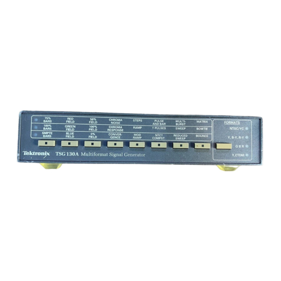
Page 23: Figure 1-1: Tsg130A Front Panel
NTSC/YC; Y, B-Y, R-Y; Y, CTDM; and GBR. Table 1–1 lists the test signals available from the TSG130A and Table 1–2 lists what is available from each rear panel output in each of the four modes. The rest of the tables, Tables 1–3 through 1–14 list the special signals and outputs... -
Page 24: For Option
Betacam level color bars (Opt 2J), 100% SMPTE level color bars, Chroma noise, Active picture markers, 5 step New, and Shallow ramp. Three signals were added on each of the component/composite matrices. It also has a color flag reference pulse from one of the Y/G outputs. 1–2 TSG130A Instruction Manual... -
Page 25: Table 1-2: Available Outputs For Standard Tsg130A In Various
Test Signal Summary and Available Outputs The following tables summarize the test signals and lists the available outputs for each of the options. Table 1–1: TSG130A test signal summary, for standard and Option 02 (black burst) Format NTSC/YC 75% color... -
Page 26: Table 1-3: Available Outputs For Tsg130A Option 2
Y, CTDM Y/0 Volts Black burst or 0 Volts CTDM (Betacam) comp sync Table 1–4: TSG130A test signal summary, for Option 01 and 01/02 Mll signals Format NTSC/YC 75% color Red field 50 IRE flat Chromi- 5-step Pulse & bar... -
Page 27: Table 1-5: Available Outputs For Tsg130A Option 01
Getting Started Table 1–4: TSG130A test signal summary, for Option 01 and 01/02 Mll signals (cont.) Format Y, B-Y, R-Y 50% flat field Valid 5-step Pulse & bar 60% multi- Matrix 75% color with window burst (Mll 3 wire) bars... -
Page 28: Table 1-6: Available Outputs For Tsg130A, Opt 01/02
(with/without sync) Y, CTDM (Mll) Y/0 Volts Black burst or 0 Volts CTDM comp sync Table 1–7: TSG130A test signal summary, for Option 2J signals Format NTSC/YC 75% color Red Field 50 IRE flat Chromi- 5-step Pulse & bar... -
Page 29: Table 1-8: Tsg130A Rear Panel Output, In Various Formats
Y, CTDM Y/0 Volts Black burst (no 0 Volts CTDM (Betacam) setup) or comp sync Table 1–9: TSG130A test signal summary, for Option 03 signals, with black burst output Format NTSC/YC 75% color Red Field 50 IRE flat Chromi- 5-step Pulse &... -
Page 30: Table 1-10: Tsg130A Rear Panel Output, In Various Formats, For Option 03
Getting Started Table 1–9: TSG130A test signal summary, for Option 03 signals, with black burst output (cont.) Format Y, B-Y, R-Y 75% color 350 mV on Y 5-step Pulse & bar 60% Multi- Matrix bars with window burst (Betacam 3 wire) -
Page 31: Table 1-11: Tsg130A Test Signal Summary, For Option 04 Mll
Getting Started Table 1–11: TSG130A test signal summary, for Option 04 Mll signals, with comp sync on the optional output Format NTSC/YC 75% color Red Field 50 IRE flat Chromi- 5-step Pulse & bar Multiburst Matrix bars field nance Noise... -
Page 32: Table 1-13: Tsg130A Test Signal Summary, For Option 05
Getting Started Table 1–12: TSG130A rear panel outputs, in various formats, for Option 04 (cont.) Rear panel output Format Format Composite S-video Black/Sync C/B-Y/B Y/G (left) Y/G (right) CTDM/R-Y/R G B R Illegal signal Comp sync Color frame (G + B) -
Page 33: Table 1-14: Available Outputs For Tsg130A, Opt 05
Getting Started Table 1–14: Available outputs for TSG130A, Opt 05 Rear panel output Format Composite S-video Black/Sync C/B-Y/B CTDM/R-Y/R NTSC/YC Black burst or NTSC 0 Volts comp sync Y, B-Y, R-Y Illegal signal Y/B-Y Black burst or (Mll) (Y + B-Y) -
Page 34: Table 1-15: Tsg130A Option Signal Comparison
Getting Started Table 1–15: TSG130A option signal comparison Standard 01/02 Signal for- Betacam Betacam Betacam Betacam Output ––– ––– Black burst Black burst Black burst Black burst Composite Black burst or –4 V or –4 V or –4 V or –4 V sync or –4 V... - Page 35 H Two BNC connector mounting boards: the top board contains one SVHS and three BNC connectors; the bottom board contains four BNC connectors. H A ribbon cable that supplies signals from the main board to the bottom BNC connector mounting board. 1–13 TSG130A Instruction Manual...
-
Page 36: Table 1-16: Power Cord Identification
Getting Started Power Cord Options The standard TSG130A power cord is a 120 V, 15 Amp cord equipped with the standard North American three-prong power plug as shown in Table 1–16. The signal generator may be ordered with the other power-cord options shown in table 1–16. - Page 37 Operating Basics...
-
Page 39: Figure 2-1: Tsg130A Front Panel
This section describes the front panel controls, the rear panel connectors, and how to use them. For information on configuring the internal jumpers see TSG130A Jumper List, Table 7–2. For information on configuring the power supply for 110 VAC or 220 VAC operation, see Selecting the Power Supply Mains Voltage, page 7–1. -
Page 40: Figure 2-2: Determining The Signal Selected
If the format is changed and no test signals are offered from that column in the selected format, the indicator moves to 75% bars. Figure 2–2: Determining the signal selected 2–2 TSG130A Instruction Manual... -
Page 41: Figure 2-3: Tsg130A Rear Panel
Rear Panel Connections This section describes the signal generator’s rear panel connections (see Figure 2–3). Figure 2–3: TSG130A rear panel Multi-purpose outputs NOTE. Only the output associated with the active signal set selected from the front panel has a valid signal on it. For example, if NTSC/YC is active there is not a valid signal on the CTDM / R-Y / R output. - Page 42 CAUTION. The audio tone output is only specified to drive a 600 W or greater impedance. It can run down to 150 W. Do not use less than 150 W. Using a lower impedance termination risks damaging the TSG130A. 9. 1 kHz audio tone output with jumper-selectable ID click. The frequency of the ID click may be changed, or the click may be disabled.
-
Page 43: Figure 2-4: Ntsc/Yc Format Signal Locations
100% color Green field 100 IRE flat Chrominance Ramp Sweep bars field frequency re- sponse SMPTE bars Blue field 0 IRE flat field Convergence Mod ramp NTC7 com- Bounce posite Figure 2–4: NTSC/YC format signal locations 2–5 TSG130A Instruction Manual... -
Page 44: Figure 2-5: Ntsc/Yc Format Rear Panel Signal Locations
50% flat field Valid 5-step Pulse & bar Multiburst bars with window 100% color 100% flat field T pulses 60% sweep Bowtie bars 0% flat field 50% reduced sweep Figure 2–6: Y, B-Y, R-Y format signal locations 2–6 TSG130A Instruction Manual... -
Page 45: Figure 2-7: Y, B-Y, R-Y Format Rear Panel Signal Locations
Figure 2–7: Y, B-Y, R-Y format rear panel signal locations Table 2–5: GBR format available signals 75% color Red field 10-step Pulse & bar Multiburst bars 100% color Green field Sweep Bowtie bars Blue filed Convergence Figure 2–8: GBR format signal locations 2–7 TSG130A Instruction Manual... -
Page 46: Figure 2-9: Gbr Format Rear Panel Signal Locations
Figure 2–9: GBR format rear panel signal locations Table 2–7: Y-CTDM format available signals 75% color 50% flat field bars 100% color 100% flat field Sweep bars 0% flat field Figure 2–10: Y-CTDM format signal locations 2–8 TSG130A Instruction Manual... -
Page 47: Figure 2-11: Y-Ctdm Format Rear Panel Signal Locations
Operating Basics Table 2–8: Y-CTDM format rear panel outputs Composite S-video C/B-Y/B CTDM/R-Y/R Black/sync Y/0 volts 0 volts CTDM No output Figure 2–11: Y-CTDM format rear panel signal locations 2–9 TSG130A Instruction Manual... - Page 48 Operating Basics 2–10 TSG130A Instruction Manual...
- Page 49 Specifications...
- Page 51 Supporting figures (waveforms and related data) follow the specifications. Performance conditions The performance requirements are valid within the environmental limits if the instrument is adjusted at 25° C ±5° C and a minimum warmup time of 20 min- utes is allowed. 3–1 TSG130A Instruction Manual...
-
Page 52: Table 3-1: Certifications And Compliances
Betacam component test signals are available on the standard instrument and on the Options 01, 03, and 2J instruments. Mll component test signals are available on the Options 01, 04, and 05 instruments. NOTE. All figures referenced in this section are located after the specifications. 3–2 TSG130A Instruction Manual... -
Page 53: Table 3-2: General Test Signal Characteristics
Y = 31 2.3 ms ±50 ns Equalizing pulse duration 50% amplitude point NTSC = 17 Y = 31 0 VDC ±50 mVDC Blanking level NTSC = 2 B-Y = 37 Y = 22 R-Y = 41 3–3 TSG130A Instruction Manual... -
Page 54: Table 3-3: General Ntsc/Yc Signal Characteristics (Ntsc/Yc Formats Only)
4 & 34 Burst 5.308 ms ±35 ns Delay from sync 19 subcarrier cycles 2.51 ms 0.1 ms Burst duration 9 subcarrier cycles 600 ns ±50 ns Breezeway duration 0° ±5° SC/H phase ≤12 ns Chrominance-to-luminance delay 3–4 TSG130A Instruction Manual... -
Page 55: Table 3-4: Ntsc/Yc Test Signal Definitions
58.83 mV Chrominance amplitude 480.24 mV Flat field 357.14 mV (50 IRE) See Figures 3–25 and 3–26 100% 714.29 mV (100 IRE) See Figures 3–27 and 3–28 0 mV (0 mV) See Figures 3–23 and 3–24 3–5 TSG130A Instruction Manual... - Page 56 Equal width packets Pedestal 285.7 mV (40 IRE) Pedestal 0.5, 1.0, 2.0, 3.0, 3.58, and 4.2 MHz Packet frequencies Packet rise time 0.5 MHz 140 ns typical (sin shaped packets) Other packets 400 ns typical (sin shaped packets) 3–6 TSG130A Instruction Manual...
- Page 57 191–214 453–476 Figures 3–15 and 3–16 Multiburst 215–238 477–500 Figures 3–39 and 3–40 100% Color Bar Option 2J 239–263 501–525 Figures 3–257, 3–258, 3-259 0 – 80 IRE ramp (Option 04) See Figures 3–230 and 3–231 3–7 TSG130A Instruction Manual...
- Page 58 Specifications Betacam component test signals are available on the TSG130A standard instrument and with instrument Options 02, 03, and 2J. Mll component test signals are available with TSG130A instrument Options 01 and 04. Table 3–5: Component test signal definitions (Y, B-Y, and R-Y format)
- Page 59 –135.1 & 135.1 mV Reference flag 420 mV Frequency 2.75 MHz 18.16 ms Slope width Line 17 (Option 03) See Figures 3–218, Not available 3–219, 3–220 Mod 5-step staircase Y level 700 mV B-Y level –231.4 mV 3–9 TSG130A Instruction Manual...
- Page 60 B-Y, R-Y pulses 4T pulse HAD 500 ns 500 ns 7T pulse HAD 875 ns 875 ns (no Option 04) Bar amplitude Y channel 0 – 714.29 mV 0 – 700 mV ±350 mV ±350 mV B-Y, R-Y 3–10 TSG130A Instruction Manual...
- Page 61 700 mV B-Y, R-Y 700 mV 60% narrow sweep See Figures 3–225, See Figures 3–242, 3–226 3–243 Y channel amplitude 420 mV B-Y, R-Y amplitude 420 mV Frequency response Y channel 200 kHz to 5.5 MHz 3–11 TSG130A Instruction Manual...
- Page 62 0.5, 1.0, 2.0, 3.0, 4.0, 0.5, 1.0, 2.0, 3.0, 4.0, 4.5 MHz 4.5 MHz R-Y, B-Y frequencies 0.2, 0.5, 1.0, 1.5, 2.0 0.2, 0.5, 1.0, 1.5, 2.0 60% multiburst (Opt 03) See Figures 3–221, Not available 3–222 3–12 TSG130A Instruction Manual...
- Page 63 167 – 190 429 – 452 T pulses See Figures 3–139, 3–140 191 – 214 453 – 476 Pulse and bar See Figures 3–136, 3–137, 3–138 215 – 238 477 – 500 60% Sweep See Figures 3–242, 3–243 3–13 TSG130A Instruction Manual...
- Page 64 Figures 3–156, 3–157 Not in Option 03 Bowtie Figures 3–88 to 3–90 Figures 3–160 to 3–162 Y channel 500 kHz sine wave Not in Option 04 C channel 1.04 MHz sine wave Not in Option 03 3–14 TSG130A Instruction Manual...
- Page 65 700 mV on B channel See Figures 3–100 to 3–102 Multiburst See Figures 3–113 and 3–114 Amplitude 420 mV centered on 350 mV White flag 420 mV centered on 350 mV Frequencies 0.5, 1, 2, 3, 4, and 5 MHz 3–15 TSG130A Instruction Manual...
- Page 66 Amplitude 0 to +8 dBu adjustable Balanced XLR impedance to drive 600 W or high-imped- ance load Frequency ≤0.5% THD Distortion (THD) Audio ID click frequency range Rate adjustable 0.2 Hz – 4 Hz (one channel) 3–16 TSG130A Instruction Manual...
- Page 67 240 VAC 180 – 250 VAC Fuse data 110 V setting 0.5 A, 250 V med. blow 230 V setting 0.25 A, 250 V med. blow Power consumption, typical 15 Watts Line frequency 48 – 62 Hz 3–17 TSG130A Instruction Manual...
- Page 68 Ten minutes each axis at any resonant point, or at 33 cycles per second. Shock 50 g, half sine, 11 ms duration, 3 guillotine-type shocks per side. Transportation Qualified under NTSB Test Procedure 1A, Category ll (24-inch drop). 3–18 TSG130A Instruction Manual...
- Page 69 CAT II Local-level mains (wall sockets). Equipment at this level includes appliances, portable tools, and similar products. Equipment is usually cord-connected CAT I Secondary (signal level) or battery operated circuits of electronic equipment 3–19 TSG130A Instruction Manual...
- Page 70 Specifications 3–20 TSG130A Instruction Manual...
-
Page 71: Figure 3-1: Options 01/02, 02, And 03 Black Burst Output
Waveform Illustrations In the following illustrations, time is referenced to the half–amplitude point (or a pulse peak) unless otherwise specified. Figure 3–1: Options 01/02, 02, and 03 black burst output Figure 3–2: Option 2J black burst output 3–21 TSG130A Instruction Manual... - Page 72 Specifications Y–C Signal Format Figure 3–3: Y channel – 75% bars Figure 3–4: C channel – 75% bars 3–22 TSG130A Instruction Manual...
-
Page 73: Figure 3-5: Y Channel - 75% Red (Same As Red Field)
Specifications Figure 3–5: Y channel – 75% red (same as red field) Figure 3–6: C channel – 75% red (same as red field) 3–23 TSG130A Instruction Manual... -
Page 74: Figure 3-7: Y Channel - 100% Bars
Specifications Figure 3–7: Y channel – 100% bars Figure 3–8: C channel – 100% bars 3–24 TSG130A Instruction Manual... - Page 75 Specifications Figure 3–9: Y channel – SMPTE bars Figure 3–10: C channel – SMPTE bars 3–25 TSG130A Instruction Manual...
-
Page 76: Figure 3-11: Y Channel - Smpte Reverse Blue Bars
Specifications Figure 3–11: Y channel – SMPTE reverse blue bars Figure 3–12: C channel – SMPTE reverse blue bars 3–26 TSG130A Instruction Manual... -
Page 77: Figure 3-13: Y Channel - Smpte Bars (Iyqb)
Specifications Figure 3–13: Y channel – SMPTE bars (IYQB) Figure 3–14: C channel – SMPTE bars (IYQB) 3–27 TSG130A Instruction Manual... -
Page 78: Figure 3-15: Y Channel - Ntc7 Composite
Specifications Figure 3–15: Y channel – NTC7 composite Figure 3–16: C channel – NTC7 composite 3–28 TSG130A Instruction Manual... -
Page 79: Figure 3-17: Y Channel - Chroma Frequency Response
Specifications Figure 3–17: Y channel – chroma frequency response Figure 3–18: C channel – chroma frequency response 3–29 TSG130A Instruction Manual... - Page 80 Specifications Figure 3–19: Y channel – blue field Figure 3–20: C channel – blue field 3–30 TSG130A Instruction Manual...
- Page 81 Specifications Figure 3–21: Y channel – green field Figure 3–22: C channel – green field 3–31 TSG130A Instruction Manual...
- Page 82 Specifications Figure 3–23: Y channel – 0% flat field Figure 3–24: C channel – 0% flat field 3–32 TSG130A Instruction Manual...
- Page 83 Specifications Figure 3–25: Y channel – 50% flat field Figure 3–26: C channel – 50% flat field 3–33 TSG130A Instruction Manual...
- Page 84 Specifications Figure 3–27: Y channel – 100% flat field Figure 3–28: C channel – 100% flat field 3–34 TSG130A Instruction Manual...
- Page 85 Specifications Figure 3–29: Y channel – chroma noise Figure 3–30: C channel – chroma noise 3–35 TSG130A Instruction Manual...
- Page 86 Specifications Figure 3–31: Y channel – pulse and bar window Figure 3–32: C channel – pulse and bar window 3–36 TSG130A Instruction Manual...
- Page 87 Specifications Figure 3–33: Y channel – 5 step Figure 3–34: C channel – 5 step 3–37 TSG130A Instruction Manual...
- Page 88 Specifications Figure 3–35: Y channel – ramp Figure 3–36: C channel – ramp 3–38 TSG130A Instruction Manual...
- Page 89 Specifications Figure 3–37: Y channel – modulated ramp Figure 3–38: C channel – modulated ramp 3–39 TSG130A Instruction Manual...
- Page 90 Specifications Figure 3–39: Y channel – multiburst Figure 3–40: C channel – multiburst 3–40 TSG130A Instruction Manual...
- Page 91 Specifications Figure 3–41: Y channel – sweep Figure 3–42: C channel – sweep 3–41 TSG130A Instruction Manual...
- Page 92 Specifications Figure 3–43: Y channel – convergence (vertical) Figure 3–44: Y channel – convergence (horizontal) 3–42 TSG130A Instruction Manual...
- Page 93 Specifications Figure 3–45: C channel – convergence Figure 3–46: Y channel – sin(x)/x 3–43 TSG130A Instruction Manual...
- Page 94 Specifications Figure 3–47: C channel – sin(x)/x Figure 3–48: Y channel – NTC7 combination 3–44 TSG130A Instruction Manual...
- Page 95 Specifications Figure 3–49: C channel – NTC7 combination Betacam Component Signals (3–Wire) Figure 3–50: Y channel – 75% bars 3–45 TSG130A Instruction Manual...
- Page 96 Specifications Figure 3–51: B–Y channel – 75% bars Figure 3–52: R–Y channel – 75% bars 3–46 TSG130A Instruction Manual...
- Page 97 Specifications Figure 3–53: Y channel – 100% bars Figure 3–54: B–Y channel – 100% bars 3–47 TSG130A Instruction Manual...
- Page 98 Specifications Figure 3–55: R–Y channel – 100% bars Figure 3–56: Y channel – 0% flat field 3–48 TSG130A Instruction Manual...
- Page 99 Specifications Figure 3–57: Y channel – 50% flat field Figure 3–58: Y channel – 100% flat field 3–49 TSG130A Instruction Manual...
- Page 100 Specifications Figure 3–59: Y channel – valid 5 step Figure 3–60: B–Y channel – valid 5 step 3–50 TSG130A Instruction Manual...
- Page 101 Specifications Figure 3–61: R–Y channel – valid 5 step Figure 3–62: Y channel – pulse and bar with window 3–51 TSG130A Instruction Manual...
- Page 102 Specifications Figure 3–63: B–Y channel – pulse and bar with window Figure 3–64: R–Y channel – pulse and bar with window 3–52 TSG130A Instruction Manual...
- Page 103 Specifications Figure 3–65: Y channel – T pulses Figure 3–66: B–Y and R–Y channels – T pulses 3–53 TSG130A Instruction Manual...
- Page 104 Specifications Figure 3–67: Y channel – line sweep Figure 3–68: B–Y and R–Y channel – line sweep 3–54 TSG130A Instruction Manual...
- Page 105 Specifications Figure 3–69: Y channel – reduced line sweep Figure 3–70: B–Y and R–Y channel – reduced line sweep 3–55 TSG130A Instruction Manual...
- Page 106 Specifications Figure 3–71: Y channel – bowtie Figure 3–72: B–Y and R–Y channels – bowtie 3–56 TSG130A Instruction Manual...
- Page 107 Specifications Figure 3–73: Y channel – bowtie markers Figure 3–74: Y channel – multiburst 3–57 TSG130A Instruction Manual...
- Page 108 Specifications Figure 3–75: B–Y and R–Y channels – multiburst Figure 3–76: Y channel – 5 step (matrix only) 3–58 TSG130A Instruction Manual...
- Page 109 Specifications Figure 3–77: B–Y and R–Y channels – 5 step (matrix only) Figure 3–78: Y channel – 75% bars 3–59 TSG130A Instruction Manual...
- Page 110 Specifications Figure 3–79: C channel – 75% bars 3–60 TSG130A Instruction Manual...
- Page 111 Specifications CTDM Format Betacam (2 Wire) Figure 3–80: Y channel – 100% bars Figure 3–81: C channel – 100% bars 3–61 TSG130A Instruction Manual...
- Page 112 Specifications Figure 3–82: C channel – flat field signals Figure 3–83: Y channel – 0% flat field 3–62 TSG130A Instruction Manual...
- Page 113 Specifications Figure 3–84: Y channel – 50% flat field Figure 3–85: Y channel – 100% flat field 3–63 TSG130A Instruction Manual...
- Page 114 Specifications Figure 3–86: Y channel – line sweep Figure 3–87: C channel – line sweep 3–64 TSG130A Instruction Manual...
- Page 115 Specifications Figure 3–88: Y channel – channel timing (bowtie) Figure 3–89: Y channel – channel timing (bowtie markers) 3–65 TSG130A Instruction Manual...
- Page 116 Specifications Figure 3–90: C channel – channel timing (bowtie) GBR Signals Figure 3–91: Green channel – 75% color bars 3–66 TSG130A Instruction Manual...
- Page 117 Specifications Figure 3–92: Blue channel – 75% color bars Figure 3–93: Red channel – 75% color bars 3–67 TSG130A Instruction Manual...
- Page 118 Specifications Figure 3–94: Green channel – 100% color bars Figure 3–95: Blue channel – 100% color bars 3–68 TSG130A Instruction Manual...
- Page 119 Specifications Figure 3–96: Red channel – 100% color bars Figure 3–97: Green channel – red field 3–69 TSG130A Instruction Manual...
- Page 120 Specifications Figure 3–98: Blue channel – red field Figure 3–99: Red channel – red field 3–70 TSG130A Instruction Manual...
- Page 121 Specifications Figure 3–100: Green channel – blue field Figure 3–101: Blue channel – blue field Figure 3–102: Red channel – blue field 3–71 TSG130A Instruction Manual...
- Page 122 Specifications Figure 3–103: Green channel – green field Figure 3–104: Blue and red channels – green field 3–72 TSG130A Instruction Manual...
- Page 123 Specifications Figure 3–105: Green channel – convergence (horizontal) Figure 3–106: Blue and red channels – convergence (horizontal) 3–73 TSG130A Instruction Manual...
- Page 124 Specifications Figure 3–107: Green channel – convergence (vertical) Figure 3–108: Blue and red channels – convergence (vertical) 3–74 TSG130A Instruction Manual...
- Page 125 Specifications Figure 3–109: Green channel – 10 step Figure 3–110: Blue and red channels – 10 step 3–75 TSG130A Instruction Manual...
- Page 126 Specifications Figure 3–111: Green channel – pulse and bar Figure 3–112: Blue and red channels – pulse and bar 3–76 TSG130A Instruction Manual...
- Page 127 Specifications Figure 3–113: Green channel – multiburst Figure 3–114: Blue and red channels – multiburst 3–77 TSG130A Instruction Manual...
- Page 128 Specifications Figure 3–115: Green channel – sweep Figure 3–116: Blue and red channels – sweep 3–78 TSG130A Instruction Manual...
- Page 129 Specifications Figure 3–117: Green channel – bowtie Figure 3–118: Blue and red channels – bowtie 3–79 TSG130A Instruction Manual...
- Page 130 Specifications Figure 3–119: Green channel – bowtie markers Figure 3–120: Blue and red channels – bowtie markers 3–80 TSG130A Instruction Manual...
- Page 131 Specifications Option 01 Signals (Mll 3–Wire) Figure 3–121: Y channel – 75% color bars Figure 3–122: B–Y channel – 75% color bars 3–81 TSG130A Instruction Manual...
- Page 132 Specifications Figure 3–123: R–Y channel – 75% color bars Figure 3–124: Y channel – 100% color bars 3–82 TSG130A Instruction Manual...
- Page 133 Specifications Figure 3–125: B–Y channel – 100% color bars Figure 3–126: R–Y channel – 100% color bars 3–83 TSG130A Instruction Manual...
- Page 134 Specifications Figure 3–127: Y channel – clip components Figure 3–128: B–Y and R–Y channels – clip components 3–84 TSG130A Instruction Manual...
- Page 135 Specifications Figure 3–129: Y channel – 50% flat field Figure 3–130: B–Y and R–Y channels – all flat fields 3–85 TSG130A Instruction Manual...
- Page 136 Specifications Figure 3–131: Y channel – 0% flat field Figure 3–132: Y channel – 100% flat field 3–86 TSG130A Instruction Manual...
- Page 137 Specifications Figure 3–133: Y channel – valid sweep Figure 3–134: B–Y channel – valid 5 step 3–87 TSG130A Instruction Manual...
- Page 138 Specifications Figure 3–135: R–Y channel – valid 5 step Figure 3–136: Y channel – pulse and bar 3–88 TSG130A Instruction Manual...
- Page 139 Specifications Figure 3–137: B–Y channel – pulse and bar Figure 3–138: R–Y channel – pulse and bar 3–89 TSG130A Instruction Manual...
- Page 140 Specifications Figure 3–139: Y channel – T pulses Figure 3–140: B–Y and R–Y channels – T pulses 3–90 TSG130A Instruction Manual...
- Page 141 Specifications Figure 3–141: Y channel – line sweep Figure 3–142: B–Y and R–Y channels – line sweep 3–91 TSG130A Instruction Manual...
- Page 142 Specifications Figure 3–143: Y channel – reduced line sweep Figure 3–144: B–Y and R–Y channels – reduced line sweep 3–92 TSG130A Instruction Manual...
- Page 143 Specifications Figure 3–145: Y channel – inter–channel timing (bowtie) Figure 3–146: B–Y and R–Y channels – inter–channel timing 3–93 TSG130A Instruction Manual...
- Page 144 Specifications Figure 3–147: Y channel – timing markers Figure 3–148: Y channel – 5 step (matrix only) 3–94 TSG130A Instruction Manual...
- Page 145 Specifications Figure 3–149: B–Y and R–Y channels – 5 step Figure 3–150: Y channel – multiburst 3–95 TSG130A Instruction Manual...
- Page 146 Specifications Figure 3–151: B–Y and R–Y channels – multiburst Mll 2–Wire Format Figure 3–152: Y channel – 75% bars 3–96 TSG130A Instruction Manual...
- Page 147 Specifications Figure 3–153: C channel – 75% bars Figure 3–154: Y channel – 100% bars 3–97 TSG130A Instruction Manual...
- Page 148 Specifications Figure 3–155: C channel – 100% bars Figure 3–156: Y channel – 0% flat field 3–98 TSG130A Instruction Manual...
- Page 149 Specifications Figure 3–157: C channel – all flat field signals Figure 3–158: Y channel – 50% flat field 3–99 TSG130A Instruction Manual...
- Page 150 Specifications Figure 3–159: Y channel – 100% flat field Figure 3–160: Y channel – inter–channel timing 3–100 TSG130A Instruction Manual...
- Page 151 Specifications Figure 3–161: C channel – inter–channel timing Figure 3–162: Y channel – inter-channel timing 3–101 TSG130A Instruction Manual...
- Page 152 Specifications Figure 3–163: Y channel – sweep Figure 3–164: C channel – sweep 3–102 TSG130A Instruction Manual...
- Page 153 Specifications Option 2J Signals (Y–C Unique Signals) Figure 3–165: Y channel – 75% color bars (no setup) Figure 3–166: C channel – 75% color bars (no setup) 3–103 TSG130A Instruction Manual...
- Page 154 Specifications Figure 3–167: Y channel – 100% color bars (no setup) Figure 3–168: C channel – 100% color bars (no setup) 3–104 TSG130A Instruction Manual...
- Page 155 Specifications Figure 3–169: Y channel – SMPTE bars (no setup) Figure 3–170: C channel – SMPTE bars (no setup) 3–105 TSG130A Instruction Manual...
- Page 156 Specifications Figure 3–171: Y channel – IYQB (no setup) Figure 3–172: C channel – IYQB (no setup) 3–106 TSG130A Instruction Manual...
- Page 157 Specifications Figure 3–173: Y channel – reverse blue bars (no setup) Figure 3–174: C channel – reverse blue bars (no setup) 3–107 TSG130A Instruction Manual...
- Page 158 Specifications Figure 3–175: Y channel – red field (no setup) Figure 3–176: C channel – red field (no setup) 3–108 TSG130A Instruction Manual...
- Page 159 Specifications Figure 3–177: Y channel – green field (no setup) Figure 3–178: C channel – green field (no setup) 3–109 TSG130A Instruction Manual...
- Page 160 Specifications Figure 3–179: Y channel – blue field (no setup) Figure 3–180: C channel – blue field (no setup) 3–110 TSG130A Instruction Manual...
- Page 161 Specifications Option 2J Signals (Y, B–Y, R–Y Unique Signals) Figure 3–181: Y channel – 75% color bars (no setup) Figure 3–182: B–Y channel – 75% color bars (no setup) 3–111 TSG130A Instruction Manual...
- Page 162 Specifications Figure 3–183: R–Y channel – 75% color bars (no setup) Figure 3–184: Y channel – 100% bars (no setup) 3–112 TSG130A Instruction Manual...
- Page 163 Specifications Figure 3–185: B–Y channel – 100% bars (no setup) Figure 3–186: R–Y channel – 100% bars (no setup) 3–113 TSG130A Instruction Manual...
- Page 164 Specifications Figure 3–187: Y channel – SMPTE bars (no setup) Figure 3–188: B–Y channel – SMPTE bars (no setup) 3–114 TSG130A Instruction Manual...
- Page 165 Specifications Figure 3–189: R–Y channel – SMPTE bars (no setup) Figure 3–190: Y channel – IYQB (no setup) 3–115 TSG130A Instruction Manual...
- Page 166 Specifications Figure 3–191: B–Y channel – IYQB (no setup) Figure 3–192: R–Y channel – IYQB (no setup) 3–116 TSG130A Instruction Manual...
- Page 167 Specifications Figure 3–193: Y channel – reverse blue bars (no setup) Figure 3–194: B–Y channel – reverse blue bars 3–117 TSG130A Instruction Manual...
- Page 168 Specifications Figure 3–195: R–Y channel – reverse blue bars Option 03 Signals (Y–C Unique Signals) Figure 3–196: Y channel – 5 step 3–118 TSG130A Instruction Manual...
- Page 169 Specifications Figure 3–197: C channel – 5 step Figure 3–198: Y channel – ramp 3–119 TSG130A Instruction Manual...
- Page 170 Specifications Figure 3–199: C channel – ramp Figure 3–200: Y channel – modulated ramp 3–120 TSG130A Instruction Manual...
- Page 171 Specifications Figure 3–201: C channel – modulated ramp Figure 3–202: Y channel – chroma response (SN B020000 and up) 3–121 TSG130A Instruction Manual...
- Page 172 Specifications Figure 3–203: C channel – chroma response Figure 3–204: Y channel – chroma response markers 3–122 TSG130A Instruction Manual...
- Page 173 Specifications Figure 3–205: Y channel – sweep Figure 3–206: C channel – sweep 3–123 TSG130A Instruction Manual...
- Page 174 Specifications Figure 3–207: Y channel – convergence (vertical) Figure 3–208: Y channel – convergence (horizontal) 3–124 TSG130A Instruction Manual...
- Page 175 Specifications Option 03 Signals (Betacam 3–Wire Unique Signals) Figure 3–209: Y channel – sin(x)/x Figure 3–210: B–Y and R–Y channels – sin(x)/x 3–125 TSG130A Instruction Manual...
- Page 176 Specifications Figure 3–211: Y channel – 5 step Figure 3–212: B–Y and R–Y channels – 5 step 3–126 TSG130A Instruction Manual...
- Page 177 Specifications Figure 3–213: Y channel – quad phase Figure 3–214: B–Y channel – quad phase 3–127 TSG130A Instruction Manual...
- Page 178 Specifications Figure 3–215: R–Y channel – quad phase Figure 3–216: Y channel – T pulses 3–128 TSG130A Instruction Manual...
- Page 179 Specifications Figure 3–217: B–Y channel – T pulses Figure 3–218: Y channel – line 17 3–129 TSG130A Instruction Manual...
- Page 180 Specifications Figure 3–219: B–Y channel – line 17 Figure 3–220: R–Y channel – line 17 3–130 TSG130A Instruction Manual...
- Page 181 Specifications Figure 3–221: Y channel – 60% multiburst Figure 3–222: B–Y and R–Y channels – 60% multiburst 3–131 TSG130A Instruction Manual...
- Page 182 Specifications Figure 3–223: Y channel – 100% narrow sweep Figure 3–224: B–Y and R–Y channels – 100% narrow sweep 3–132 TSG130A Instruction Manual...
- Page 183 Specifications Figure 3–225: Y channel – 60% narrow sweep Figure 3–226: B–Y and R–Y channels – 60% narrow sweep 3–133 TSG130A Instruction Manual...
- Page 184 Specifications Figure 3–227: Y channel – 12.5T pulses Figure 3–228: B–Y channel – 12.5T pulses 3–134 TSG130A Instruction Manual...
- Page 185 Specifications Figure 3–229: R–Y channel – 12.5T pulses Option 04 Signals (Y–C Unique Signals) Figure 3–230: Y channel – 0–80 IRE mod ramp 3–135 TSG130A Instruction Manual...
- Page 186 Specifications Figure 3–231: C channel – 0–80 IRE mod ramp Figure 3–232: Y channel – chroma response 3–136 TSG130A Instruction Manual...
- Page 187 Specifications Figure 3–233: C channel – chroma response Figure 3–234: Y channel – chroma response markers 3–137 TSG130A Instruction Manual...
- Page 188 Specifications Option 04 Signals (Mll 3-Wire Unique Signals) Figure 3–235: Y channel – level reference (lines 182–262) Figure 3–236: Y channel – 5 step 3–138 TSG130A Instruction Manual...
- Page 189 Specifications Figure 3–237: B–Y and R–Y channels – 5 step Figure 3–238: Y channel – T pulses 3–139 TSG130A Instruction Manual...
- Page 190 Specifications Figure 3–239: B–Y and R–Y channels – T pulses Figure 3–240: Y channel – 100% sweep 3–140 TSG130A Instruction Manual...
- Page 191 Specifications Figure 3–241: B–Y and R–Y channels – 100% sweep Figure 3–242: Y channel – 60% sweep 3–141 TSG130A Instruction Manual...
- Page 192 Specifications Figure 3–243: B–Y and R–Y channels – 60% sweep Figure 3–244: Y channel – 100% bowtie and markers 3–142 TSG130A Instruction Manual...
- Page 193 Specifications Figure 3–245: B–Y and R–Y channels – 100% bowtie Option 05 Signals (DVCPRO) –100 –200 –300 –300 62.0 TIME in ms Figure 3–246: Y channel – Chroma Noise 3–143 TSG130A Instruction Manual...
- Page 194 Specifications –100 –200 –300 62.0 TIME in ms Figure 3–247: B-Y channel – Chroma Noise –100 –200 –300 62.0 TIME in ms Figure 3–248: R-Y channel – Chroma Noise 3–144 TSG130A Instruction Manual...
- Page 195 Figure 3–249: Y channel – 5 Step (Option 05) –70 –100 –200 –210 –300 –350 13.778 21.481 29.185 36.889 44.593 52.296 60.000 TIME in ms Figure 3–250: B-Y and R-Y channel – 5 Step (Option 05) 3–145 TSG130A Instruction Manual...
- Page 196 Figure 3–251: Y channel – SMPTE Level 100% Colorbars 350.0 231.9 118.1 –100 –118.1 –200 –231.9 –300 –350.0 –400 15.8 22.5 29.1 35.7 42.4 49.0 55.6 TIME in ms Figure 3–252: B-Y channel – SMPTE Level 100% Colorbars 3–146 TSG130A Instruction Manual...
- Page 197 –400 15.8 22.5 29.1 35.7 42.4 49.0 55.6 TIME in ms Figure 3–253: R-Y channel – SMPTE Level 100% Colorbars -285.7 -300 mV for Matrix signal Figure 3–254: Y channel – 100% Color Bars Option 2J 3–147 TSG130A Instruction Manual...
- Page 198 Specifications Figure 3–255: B–Y channel – 100% Color Bars Option 2J Figure 3–256: R–Y channel – 100% Color Bars Option 2J 3–148 TSG130A Instruction Manual...
- Page 199 Specifications –100 –200 –300 –400 9.037 62.370 63.555 TIME in ms Figure 3–257: Y channel – Active Picture Marker 3–149 TSG130A Instruction Manual...
- Page 200 Specifications 3–150 TSG130A Instruction Manual...
- Page 201 WARNING The following servicing instructions are for use only by qualified personnel. To avoid injury, do not perform any servicing other than that stated in the operating instructions unless you are qualified to do so. Refer to all safety summaries before performing any service.
- Page 203 Block Diagram...
- Page 205 Block Diagram TSG130A Simplified block diagram 4–1 TSG130A Instruction Manual...
- Page 206 Block Diagram 4–2 TSG130A Instruction Manual...
- Page 207 Performance Verification...
- Page 209 Performance Check Procedures This section consists of checklists and detailed procedures that can be used to check the performance of the TSG130A against specifications. Table 5–1 is a list of equipment and corresponding performance requirements needed for the following performance check procedures.
- Page 210 16. Luminance rise times: 250 ns ±25 ns 17. Horizontal sync duration, vertical serration duration, equalizing pulse duration: sync = 4.7 ms ±50 ns; vertical serration = 4.7 ms ±50 ns; equalizing pulse = 2.3 ms ±50 ns 5–2 TSG130A Instruction Manual...
- Page 211 40. Blanking level: 0 mVDC ±50 mVDC R-Y Signals 41. R-Y rise times: color bars 400 ns ±40 ns; other signal transitions 250 ns ±25 ns 42. R-Y sine squared pulse accuracy: HADs accurate within 25 ns 5–3 TSG130A Instruction Manual...
- Page 212 62. Total harmonic distortion: ≤0.5% THD Audio Outputs 63. Black burst amplitude: 7.5 IRE ±1 IRE; 0 IRE ±1 IRE (Option 2J) Black Burst Output (Options 01/02, 02, 03, 2J) 64. Black burst blanking width: 10.9 ± 5–4 TSG130A Instruction Manual...
- Page 213 = 2.3 66. Amplitude: –4.0 V ±0.5 V 67. Rise and fall times: 140 ns ±20 ns Color Flag Reference 68. Amplitude and position Pulse (Option 03) Color Frame Square Wave 69. Amplitude and position (Option 04) 5–5 TSG130A Instruction Manual...
- Page 214 Set the frequency counter to count using ratio A/B. c. CHECK that the measured oscillator frequency is 14.31818 MHz ±28 Hz at room temperature. The following table lists the suggested Tektronix 1780R setup for the perfor- mance checks. 5–6...
- Page 215 Right display WFM horizontal ONE/LINE Filter FLAT Waveform gain Figure 5–2: Basic performance check setup NOTE. If the TSG130A being checked has an optional black burst signal, use that signal as the waveform monitor’s EXT REF input. 5–7 TSG130A Instruction Manual...
- Page 216 CHECK for a burst amplitude of 285.7 mV ±5.7 mV (40 IRE ±0.8 IRE). 5. Steps (5-step) staircase linearity <1% a. Connect the test equipment as shown in Figure 5–2. b. Display CH A on the waveform monitor. 5–8 TSG130A Instruction Manual...
- Page 217 Display CH A on the waveform monitor. c. Select the Pulse & Bar signal in NTSC/YC format from the signal generator. d. Set the waveform monitor to view the bottom of the 12.5T modulated pulse. 5–9 TSG130A Instruction Manual...
- Page 218 Performance Check Procedures e. Use the Chroma/Luma measurement mode of the Tektronix 1780R to measure both C/Y delay and gain. CHECK that the delay is <12 ns and the gain is <1%. g. Compare the measured values for luminance amplitude (from part 6) and chrominance amplitude (from part 7).
- Page 219 100 and 0 IRE respectively. e. Using the timing cursor, measure the time from the 50 IRE points of the sync. CHECK that the sync duration is 4.7 ms ±50 ns. 5–11 TSG130A Instruction Manual...
- Page 220 Use the variable vertical gain to normalize the sync to 0 – 100 IRE. e. CHECK that horizontal sync duration between 50% points is 4.7 ms ±50 ns. Set the waveform monitor to display the serrations and equalizing pulses in the vertical interval. 5–12 TSG130A Instruction Manual...
- Page 221 CHECK for differential phase of ≤0.3°. Set the test equipment to measure differential gain. Again, use a double trace, if possible. g. CHECK that the differential gain of the modulated ramp is ≤0.3%. 5–13 TSG130A Instruction Manual...
- Page 222 23. Sync amplitude: 285.7 mV ±2%; 300.0 mV ±2% for MII 3-wire signals a. Connect the test equipment as shown in Figure 5–2. b. Display CH B1 on the waveform monitor. c. Select any signal from the signal generator in the NTSC/YC format. 5–14 TSG130A Instruction Manual...
- Page 223 100 and 0 IRE respectively. Using the timing cursor, measure the time from the 50 IRE points of the sync. CHECK that the sync duration is 5.0 ms ±50 ns. 5–15 TSG130A Instruction Manual...
- Page 224 0.2 milliseconds (about 3 lines) of the bar. factor <0.6% ≤1% of peak 28. Ringing: K a. Connect the test equipment as shown in Figure 5–2. b. Display CH B1 on the waveform monitor. 5–16 TSG130A Instruction Manual...
- Page 225 Set the waveform monitor to display the 3T pulse on the T pulses signal in Y, B-Y, R-Y format. h. Use the variable gain control to normalize the pulse to 100 IRE and use the horizontal magnification to make the pulse fill the waveform monitor display. 5–17 TSG130A Instruction Manual...
- Page 226 Select the chroma response signal from the signal generator in NTSC/ YC format. d. CHECK that the amplitude of the chrominance is flat, within 1%, using the voltage cursors. 33. Chrominance amplitude: ±1% a. Connect the test equipment as shown in Figure 5–2. 5–18 TSG130A Instruction Manual...
- Page 227 Set the signal generator to output the chroma response signal in the NTSC/YC format. c. Display CH B2 on the waveform monitor using external reference. d. Set the waveform monitor to display the rise on the B2 channel. 5–19 TSG130A Instruction Manual...
- Page 228 Select any signal from the signal generator in Y, B-Y, R-Y format. d. Switch the display from DC coupled to ground reference. e. Use the vertical position adjustment of the waveform monitor to set the ground line to a convenient reference graticule. 5–20 TSG130A Instruction Manual...
- Page 229 Using the timing cursors, measure the time between the 50 IRE points. CHECK that the HAD of the 4T pulse is 500 ns ±25 ns. 5–21 TSG130A Instruction Manual...
- Page 230 Reset the time cusrors to 400 ns. h. With the timing cursors set to track 400 ns, move the cursors to other rising and falling edges and observe 10% and 90% points. 5–22 TSG130A Instruction Manual...
- Page 231 2-3 position. 43. Amplitude accuracy: ±1% a. Connect the equipment as shown in Figure 5–3. b. Display CH B1 on the waveform monitor. c. Select the 100% bars signal in GBR format from the signal generator. 5–23 TSG130A Instruction Manual...
- Page 232 Display CH B2 on the waveform monitor using external reference. c. Select GBR format and the sweep test signal from the signal generator. d. Use the WFM + CAL feature to match the top of the lower waveform with the bottom of the upper. 5–24 TSG130A Instruction Manual...
- Page 233 CHECK that the field bar tilts no more than 0.5% over its length. Ignore the first and last 3 lines of the signal. 51. Pulse-to-bar ratio: 1:1 ±1% a. Connect the equipment as shown in Figure 5–3. 5–25 TSG130A Instruction Manual...
- Page 234 Select GBR format and red field test signal from the signal generator. d. Use the WFM + CAL to align to top of the lower waveform with the blanking level of the upper. e. CHECK that signal amplitude is 700 mV ±7 mV (1%). 5–26 TSG130A Instruction Manual...
- Page 235 CHECK that the inverted pulse tip is within 1% of blanking level, using the WFM + CAL signal. Inter-Channel Timing and 58. B-Y to Y Timing: within 5 ns Amplitude a. Connect the equipment as shown in Figure 5–3. 5–27 TSG130A Instruction Manual...
- Page 236 Display CH B1, B2, and B3 on the waveform monitor using external reference in overlay mode. c. Select GBR format and the 100% bars test signal from the signal generator. d. Use the channel offset to set the bottom of the waveforms to the 0 IRE graticule. 5–28 TSG130A Instruction Manual...
- Page 237 CHECK that the signal is flat within 2% to 4.2 MHz. Figure 5–5: Setup to check S-video output 62. Total harmonic distortion: TDH ≤0.5% Audio Output a. Disable the CH 1 ID click by moving jumper J12 to pins 2 and 3. 5–29 TSG130A Instruction Manual...
- Page 238 Return jumper J12 to pins 1 and 2. Move the cable at the signal generator from audio channel 1 to audio channel 2. g. CHECK that the THD on channel 2 is ≤0.5%. Figure 5–6: Setup to measure total harmonic distortion 5–30 TSG130A Instruction Manual...
- Page 239 Use the voltage cursor to measure the time between the 4 IRE point on the front porch and the 4 IRE point on the back porch. d. CHECK that the blanking width is 10.9 ±0.2 ms. 5–31 TSG130A Instruction Manual...
- Page 240 4.7 ms ±50 ns. CHECK that the time between the 50% points of the equalizing pulse is 2.3 ms ±50 ns. 66. Amplitude: –4.0 V ±0.5 V a. Connect the equipment as shown in Figure 5–8. 5–32 TSG130A Instruction Manual...
- Page 241 Expand the oscilloscope horizontal to display this pulse at 100 ms/div. CHECK that the color frame reference pulse is approximately 200 ms in duration, and aligns with the vertical sync pulse interval of the black burst signal. 5–33 TSG130A Instruction Manual...
- Page 242 CHECK that the amplitude of the color frame square wave is –5 V within 200 mV. d. CHECK that the timing of the color frame square wave is low for fields 1 and 2 and high for fields 3 and 4. The transition should occur on line 11. 5–34 TSG130A Instruction Manual...
- Page 243 Adjustment Procedure...
- Page 245 The parts in these steps are loaded only in Option 04. Comp sync channel sin(x)/x compensation – C278 The parts in step 26 are factory set. Do not adjust unless these parts are out of spec. Comp sync interchannel timing – L31, L32, L34, L35, L36 6–1 TSG130A Instruction Manual...
- Page 246 2. Audio output amplitude – R123, R122 a. Connect the equipment as shown in Figure 6–2 with the following distortion analyzer settings: Table 6–2: Distortion analyzer settings Function Setting Input level range Auto range dBm switch 6–2 TSG130A Instruction Manual...
- Page 247 +8 dBm). d. Return jumper J12 to the 1–2 position. e. Move the TSG130A cable from audio channel 1 to audio channel 2. Adjust R122 to obtain the desired output level for audio 2 (factory setting is +8 dBm).
- Page 248 Connect the equipment as shown in Figure 6–3. b. Adjust R126 for the desired interval between ID clicks. The range of adjustment is about 0.2 – 4 seconds. Figure 6–4: Basic setup for calibration procedures 6–4 TSG130A Instruction Manual...
- Page 249 One/line WFM readout Waveform gain NOTE. If the TSG130A under check has the optional black burst signal installed, use that signal as the waveform monitor Ext Ref input. 4. Y/G channel DC level and gain – R82, R79 a. Begin with the 1780R reference setup shown in Table 6–3 and Fig- ure 6–4 and select channel B1 as the input.
- Page 250 Begin with the 1780R reference setup and display channel B2 using external reference. b. Select the 100% bars signal in Y, B-Y, R-Y format from the TSG130A. c. Set the 1780R to GND coupling and center the trace on a reference graticule.
- Page 251 10. CTDM/R-Y/R channel DC level and gain – R101 & R98 a. Begin with the 1780R reference setup and select channel B3 as the input using external reference. b. Select the 100% bars signal in GBR format from the TSG130A. 6–7 TSG130A Instruction Manual...
- Page 252 Switch to DC coupling and adjust R101 for a blanking level of 0 V by setting the blanking level to the reference graticule. e. Select the red field signal in GBR format from the TSG130A. Select WFM + CAL at the right display section of the 1780R, set CAL for 700 mV, and adjust R98 to match the top of the lower waveform with the blanking level of the upper.
- Page 253 14. Composite blanking level and gain – R20, R18 a. Begin with the reference setup and select channel A as the input. b. Select the steps (5-step) signal in NTSC/YC format from the TSG130A. c. Set the 1780R to GND coupling and center the trace on a reference graticule.
- Page 254 Begin with the reference setup of the measurement set and select B1-B2 as the input. b. Select the bowtie signal in GBR format from the TSG130A. c. Adjust C30 to place the crossover point of the bowtie on the center (highest amplitude) marker.
- Page 255 18. Chrominance-to-luminance delay a. Begin with the reference setup and select channel A as the input. b. Select the pulse & bar signal in NTSC/YC format from the TSG130A. c. Display the bottom of the 12.5T modulated pulse, using horizontal magnification to view the sine wave distortion.
- Page 256 22. Black burst channel (sin(x))/x compensation – C278 a. Begin with the reference setup and select channel A as the input. b. Select any signal in the NTSC/YC format from the TSG130A. c. Choose WFM + CAL at the 1780R and set it to 40 IRE.
- Page 257 Begin with the 1780R reference setup and select channel A as the input using external reference. b. Select the 0% flat field in NTSC/YC format from the TSG130A. c. Put the vectorscope in SCH mode. d. CHECK that the phase difference (SCH) between the black burst and the composite signal is <3°.
- Page 258 Adjust C69 so that the burst amplitude is 285.7 mV. Figure 6–8: Comp sync inter-channel timing setup NOTE. The parts in this step are factory set. Do not adjust these parts unless they are out of spec. 6–14 TSG130A Instruction Manual...
- Page 259 Set the equipment up as shown in Figure 6–8 and select channel A as the input using external reference. b. Select the 0% flat field in NTSC/YC format from the TSG130A. c. Put the vectorscope in SCH mode. d. CHECK that the phase difference (SCH) between the 0% flat field and comp sync is <3°.
- Page 260 Adjustment Procedures 6–16 TSG130A Instruction Manual...
- Page 261 Maintenance...
- Page 263 Selecting the Power Supply Mains Voltage The TSG130A is shipped from the factory configured for 110 VAC, 60 Hz operation. To configure the TSG130A for 220 VAC operation, follow this procedure.
- Page 264 6. Lift the board and flip it at the same time (J128, attached to the board toward the front of the instrument, forces it to flip over revealing the component side of the board). 7. The adjustments for the black burst and comp sync can now be made. 7–2 TSG130A Instruction Manual...
- Page 265 (red field, blue field, green field) when J2 is in the 2–3 position. No other signals are changed and the TSG130A can be left in this mode if the diagnostic signals are more useful than the standard signal set in a particular application.
- Page 266 Maintenance Setting the Internal Jumpers Table 7–2 lists the available jumper functions that enable you to set the instrument for individual preferences. Table 7–2: TSG130A jumper list Jumper Position Function Diagnostic signals 1–2 Enables standard front panel operation. 2–3 Allows selection of diagnostic test signals.
- Page 267 Replaceable Electrical Parts...
- Page 269 Replaceable Electrical Parts This section contains a list of the electrical components for the TSG130A. Use this list to identify and order replacement parts. Parts Ordering Information Replacement parts are available through your local Tektronix field office or representative. Changes to Tektronix products are sometimes made to accommodate improved components as they become available and to give you the benefit of the latest improvements.
- Page 270 Chassis-mounted parts have no assembly number prefix, and they are located at the end of the electrical parts list. Tektronix part number Use this part number when ordering replacement parts from Tektronix. 3 and 4 Serial number Column three indicates the serial number at which the part was first effective. Column four indicates the serial number at which the part was discontinued.
- Page 271 3005 SW 154TH TERRACE #3 BEAVERTON OR 97006 76493 BELL INDUSTRIES INC 19070 REYES AVE COMPTON CA 90224–5825 JW MILLER DIV PO BOX 5825 80009 TEKTRONIX INC 14150 SW KARL BRAUN DR BEAVERTON OR 97077–0001 PO BOX 500 8–3 TSG130A Instruction Manual...
- Page 272 C/O PANEL COMPONENTS CORP S4307 SCHAFFNER ELECTRONIK AG LUTERBACH SWITZERLAND TK1345 ZMAN & ASSOCIATES TK1450 TOKYO COSMOS ELECTRIC CO LTD 2–268 SOBUDAI ZAWA KANAGAWA 228 JAPAN TK2058 TDK CORPORATION OF AMERICA 1600 FEEHANVILLE DRIVE MOUNT PROSPECT, IL 60056 8–4 TSG130A Instruction Manual...
- Page 273 58361 Q6480/MV5274C *MOUNTING PARTS* 352–1012–00 HOLDER,LED:BLK,ABS 80009 352–1012–00 *END MOUNTING PARTS* A1DS215 150–1029–00 LT EMITTING DIO:GRN,565NM,35MA 58361 Q6480/MV5274C *MOUNTING PARTS* 352–1012–00 HOLDER,LED:BLK,ABS 80009 352–1012–00 *END MOUNTING PARTS* A1DS218 150–1029–00 LT EMITTING DIO:GRN,565NM,35MA 58361 Q6480/MV5274C *MOUNTING PARTS* 8–5 TSG130A Instruction Manual...
- Page 274 260–2675–00 Switch, push, gr LED 80009 260–2675–00 *ATTACHED PARTS* 366–0682–00 PUSH BTN:LIGHTED CAP,INSERT ASSY 80009 366–0682–00 *END ATTACHED PARTS* A1S205 260–2675–00 Switch, push, gr LED 80009 260–2675–00 *ATTACHED PARTS* 366–0682–00 PUSH BTN:LIGHTED CAP,INSERT ASSY 80009 366–0682–00 8–6 TSG130A Instruction Manual...
- Page 275 P20.3 A1U209 160–9207–00 671–2710–01 IC,DGTL:CMOS,PLD;EEPLD,16V8,25NS,90MA,PRGM;16V8–25,DI 80009 160–9207–00 P20.3 A1U209 160–9205–00 671–2709–01 IC,DGTL:CMOS,PLD;EEPLD,16V8,25NS,90MA,PRGM;16V8–25,DI 80009 160–9205–00 P20.3 A1U209 160–9203–00 671–2711–01 IC,DGTL:CMOS,PLD;EEPLD,16V8,25NS,90MA;PRGM,16V8–25,DI 80009 160–9203–00 P20.3,TUBE A1U209 163–1412–00 671–5138–00 IC,DIGITAL:FTTL,FLIP FLOP,OCTAL D–TYPE,FLOW THRU, 163–1412–00 3–STATE,74F574, (OPTION 5 ONLY) *MOUNTING PARTS* 8–7 TSG130A Instruction Manual...
- Page 276 CAP,FXD,CER:MLC;0.01UF,20%,50V,X7R,0.20 X 0.20;RDL 04222 SR205C103MAA A2C40 281–0775–01 CAP,FXD,CER:MCL;0.1UF,20%,50V,Z5U,0.170 X 0.100;AXIAL 04222 SA105E104MAA A2C41 281–0775–01 CAP,FXD,CER:MCL;0.1UF,20%,50V,Z5U,0.170 X 0.100;AXIAL 04222 SA105E104MAA A2C42 283–0177–05 CAP,FXD,CER DI:1UF,+80–20%,25V 04222 SR303E105ZAAAP1 A2C43 283–0220–00 CAP,FXD,CER:MLC;0.01UF,20%,50V,X7R,0.20 X 0.20;RDL 04222 SR205C103MAA A2C46 281–0898–00 CAP,FXD,CER DI:7.5PF,+/–0.5PF,500V 04222 MA107A7R5DAA 8–8 TSG130A Instruction Manual...
- Page 277 CAP,FXD,CER:MCL;0.1UF,20%,50V,Z5U,0.170 X 0.100;AXIAL 04222 SA105E104MAA A2C89 281–0775–01 CAP,FXD,CER:MCL;0.1UF,20%,50V,Z5U,0.170 X 0.100;AXIAL 04222 SA105E104MAA A2C90 290–0973–00 CAP,FXD,ELCTLT:100UF,20%,25VDC 24165 513D107M025BB4D A2C91 283–0220–00 CAP,FXD,CER:MLC;0.01UF,20%,50V,X7R,0.20 X 0.20;RDL 04222 SR205C103MAA A2C92 283–0177–05 CAP,FXD,CER DI:1UF,+80–20%,25V 04222 SR303E105ZAAAP1 A2C93 283–0220–00 CAP,FXD,CER:MLC;0.01UF,20%,50V,X7R,0.20 X 0.20;RDL 04222 SR205C103MAA 8–9 TSG130A Instruction Manual...
- Page 278 SA105E104MAA A2C167 281–0775–01 CAP,FXD,CER:MCL;0.1UF,20%,50V,Z5U,0.170 X 0.100;AXIAL 04222 SA105E104MAA A2C168 281–0775–01 CAP,FXD,CER:MCL;0.1UF,20%,50V,Z5U,0.170 X 0.100;AXIAL 04222 SA105E104MAA A2C169 281–0775–01 CAP,FXD,CER:MCL;0.1UF,20%,50V,Z5U,0.170 X 0.100;AXIAL 04222 SA105E104MAA A2C170 281–0775–01 CAP,FXD,CER:MCL;0.1UF,20%,50V,Z5U,0.170 X 0.100;AXIAL 04222 SA105E104MAA A2C172 281–0775–01 CAP,FXD,CER:MCL;0.1UF,20%,50V,Z5U,0.170 X 0.100;AXIAL 04222 SA105E104MAA 8–10 TSG130A Instruction Manual...
- Page 279 CAP,FXD,CER:MLC;0.01UF,20%,50V,X7R,0.20 X 0.20;RDL 04222 SR205C103MAA A2C274 281–0775–01 CAP,FXD,CER:MCL;0.1UF,20%,50V,Z5U,0.170 X 0.100;AXIAL 04222 SA105E104MAA A2C275 281–0775–01 CAP,FXD,CER:MCL;0.1UF,20%,50V,Z5U,0.170 X 0.100;AXIAL 04222 SA105E104MAA A2C276 290–0973–00 CAP,FXD,ELCTLT:100UF,20%,25VDC 24165 513D107M025BB4D A2C277 281–0898–00 CAP,FXD,CER DI:7.5PF,+/–0.5PF,500V 04222 MA107A7R5DAA A2C278 281–0153–00 671–2715–01 CAP,VAR,AIR DI:1.7–10PF,250V 80009 281–0153–00 8–11 TSG130A Instruction Manual...
- Page 280 CAP,FXD,MICA DI:670PF,1%,300V 80009 283–0692–00 A2C305 283–0796–01 CAP,FXD,MICA DI:100PF,5%,500V,TAPE & AMMO 09023 CDA10FD101J03 A2CR4 152–0601–01 SEMICOND DVC,DI:RECTIFIER,SI,150V,1A,35NS 04713 MUR115RL A2CR5 152–0601–01 SEMICOND DVC,DI:RECTIFIER,SI,150V,1A,35NS 04713 MUR115RL A2CR6 152–0601–01 SEMICOND DVC,DI:RECTIFIER,SI,150V,1A,35NS 04713 MUR115RL A2CR7 152–0601–01 SEMICOND DVC,DI:RECTIFIER,SI,150V,1A,35NS 04713 MUR115RL 8–12 TSG130A Instruction Manual...
- Page 281 80009 114–0364–00 A2L11 114–0366–00 COIL,RF:VAR,2.40–2.70UH,Q MIN 190 @ 2.6 UH, POT CORE 54937 114–0366–00 A2L12 114–0366–00 COIL,RF:VAR,2.40–2.70UH,Q MIN 190 @ 2.6 UH, POT CORE 54937 114–0366–00 A2L13 108–1491–00 COIL,RF:FXD,TOROIDAL,9.0UH,5.5% TK1345 108–1491–00 A2L14 120–1180–00 XFMR,RF:VAR 80009 120–1180–00 8–13 TSG130A Instruction Manual...
- Page 282 114–0364–00 671–2650–01 COIL,RF:VAR,1.42–1.68UH 80009 114–0364–00 A2L34 114–0364–00 671–2717–01 COIL,RF:VAR,1.42–1.68UH 80009 114–0364–00 A2L34 114–0364–00 671–2716–01 COIL,RF:VAR,1.42–1.68UH 80009 114–0364–00 A2L34 114–0364–00 671–2718–01 COIL,RF:VAR,1.42–1.68UH 80009 114–0364–00 A2L35 114–0366–00 671–2715–01 COIL,RF:VAR,2.40–2.70UH,Q MIN 190 @ 2.6 UH, POT CORE 54937 114–0366–00 8–14 TSG130A Instruction Manual...
- Page 283 AMPL;2N3906,TO–92 EBC A2Q6 151–0188–00 XSTR,SIG:BIPOLAR,PNP;40V,200MA,250MHZ, 80009 151–0188–00 AMPL;2N3906,TO–92 EBC A2Q7 151–0188–00 XSTR,SIG:BIPOLAR,PNP;40V,200MA,250MHZ, 80009 151–0188–00 AMPL;2N3906,TO–92 EBC A2Q8 151–0190–00 XSTR,SIG:BIPOLAR,NPN;40V,200MA,300MHZ, 80009 151–0190–00 AMPL;2N3904,TO–92 EBC A2Q9 151–0190–00 XSTR,SIG:BIPOLAR,NPN;40V,200MA,300MHZ, 80009 151–0190–00 AMPL;2N3904,TO–92 EBC A2Q10 151–0190–00 XSTR,SIG:BIPOLAR,NPN;40V,200MA,300MHZ, 80009 151–0190–00 AMPL;2N3904,TO–92 EBC 8–15 TSG130A Instruction Manual...
- Page 284 IAL,T&R,SM BODY A2R45 322–3056–01 RES,FXD,FILM:37.4 OHM,0.5%,0.2W,TC=T0 57668 CRB20 DXE 37E4 A2R46 322–3085–07 RES,FXD:MET FILM;75 OHM,0.1%,0.2W,TC=25 PPM;AX- 91637 CCF502–C75ROOBT IAL,T&R,SM BODY A2R47 322–3001–00 RES,FXD:MET FILM;10 OHM,1%,0.2W,TC=100 PPM;AX- 80009 322–3001–00 IAL,T&R,SM BODY A2R48 317–0036–00 RES,FXD,CMPSN:3.6 OHM,5%,0.125W 80009 317–0036–00 8–16 TSG130A Instruction Manual...
- Page 285 CRB20 FXE 2K21 IAL,T&R,SM BODY A2R89 317–0036–00 RES,FXD,CMPSN:3.6 OHM,5%,0.125W 80009 317–0036–00 A2R90 317–0036–00 RES,FXD,CMPSN:3.6 OHM,5%,0.125W 80009 317–0036–00 A2R91 322–3001–00 RES,FXD:MET FILM;10 OHM,1%,0.2W,TC=100 PPM;AX- 80009 322–3001–00 IAL,T&R,SM BODY A2R92 322–3085–07 RES,FXD:MET FILM;75 OHM,0.1%,0.2W,TC=25 PPM;AX- 91637 CCF502–C75ROOBT IAL,T&R,SM BODY 8–17 TSG130A Instruction Manual...
- Page 286 RES,FXD:MET FILM;1K OHM,1%,0.2W,TC=100 PPM;AX- 57668 CRB20 FXE 1K00 IAL,T&R,SM BODY A2R211 322–3085–07 RES,FXD:MET FILM;75 OHM,0.1%,0.2W,TC=25 PPM;AX- 91637 CCF502–C75ROOBT IAL,T&R,SM BODY A2R212 307–0650–00 RES NTWK,FXD,FI:9,2.7K OHM,5%,0.150W 11236 750–101–R2.7K A2R213 322–3193–00 RES,FXD:MET FILM;1K OHM,1%,0.2W,TC=100 PPM;AX- 57668 CRB20 FXE 1K00 IAL,T&R,SM BODY 8–18 TSG130A Instruction Manual...
- Page 287 RES,VAR,TRMR:CERMET;5K OHM,20%,0.5W,0.197 SQ,TOP TK1450 GF06UT 5K ADJUST;T&R A2R231 311–2234–00 671–2650–01 RES,VAR,TRMR:CERMET;5K OHM,20%,0.5W,0.197 SQ,TOP TK1450 GF06UT 5K ADJUST;T&R A2R231 311–2234–00 671–2717–01 RES,VAR,TRMR:CERMET;5K OHM,20%,0.5W,0.197 SQ,TOP TK1450 GF06UT 5K ADJUST;T&R A2R231 311–2234–00 671–2716–01 RES,VAR,TRMR:CERMET;5K OHM,20%,0.5W,0.197 SQ,TOP TK1450 GF06UT 5K ADJUST;T&R 8–19 TSG130A Instruction Manual...
- Page 288 322–3034–00 RES,FXD,METAL FILM;22.1 OHM,1%,0.2W,TC=25 PPM 80009 322–3034–00 A2R379 322–3277–00 RES,FXD,7.50K OHM,0.2W,1% 80009 322–3277–00 A2R380 322–3277–00 RES,FXD,7.50K OHM,0.2W,1% 80009 322–3277–00 A2R381 322–3277–00 RES,FXD,7.50K OHM,0.2W,1% 80009 322–3277–00 A2R382 322–3277–00 RES,FXD,7.50K OHM,0.2W,1% 80009 322–3277–00 A2T1 120–1885–01 XFMR,PWR: 80009 120–1885–01 8–20 TSG130A Instruction Manual...
- Page 289 BRS,W/ RED NYL CLR A2U1 156–4024–00 IC,LIN:BIPOLAR,OP–AMP;190MHZ,CUR FEEDBACK,1 TO 40 80009 156–4024–00 GAIN RANGE;AD9617JN,DIP08.3 A2U2 156–4024–00 IC,LIN:BIPOLAR,OP–AMP;190MHZ,CUR FEEDBACK,1 TO 40 80009 156–4024–00 GAIN RANGE;AD9617JN,DIP08.3 A2U3 156–0527–00 IC,LIN:BIPOLAR,VR;NEG,15V,1.0A,4%;MC7915CT,TO–220 80009 156–0527–00 A2U4 156–4170–00 IC,LIN:BIPOLAR OP–AMP;CUR FEEDBACK,100MHZ,HI OUT 80009 156–4170–00 CUR;OPA603AP,DIP08.3 8–21 TSG130A Instruction Manual...
- Page 290 160–9230–00 671–2718–01 IC,MEMORY:CMOS,PROM;32K X 80009 160–9230–00 8,50NS,RGTR;PRGM,7C277.DIP28.3 A2U23 163–1419–00 671–5139–00 IC,MEMORY:CMOS,PROM,32K X 8, 50NS,REGISTERED,7C277 163–1419–00 (OPTION 5 ONLY) 80009 *MOUNTING PARTS* 136–1038–00 SKT,DIP: 00779 2–641873–1 *END MOUNTING PARTS* A2U25 160–9056–01 671–2713–01 IC,MEMORY:CMOS,PROM;32K X 80009 160–9056–01 8,50NS,RGTR;7C277,PRGM,DIP28.3 8–22 TSG130A Instruction Manual...
- Page 291 *MOUNTING PARTS* 136–1038–00 SKT,DIP: 00779 2–641873–1 *END MOUNTING PARTS* A2U29 156–3019–00 IC,LIN:BIPOLAR,V REF;1.235V,1.0%,150PPM,SHUNT,MICRO- 27014 LM385BZ–1.2 POWER;LM385BZ–1.2,TO–92 A2U30 156–4170–00 IC,LIN:BIPOLAR OP–AMP;CUR FEEDBACK,100MHZ,HI OUT 80009 156–4170–00 CUR;OPA603AP,DIP08.3 A2U31 156–6345–00 IC,CONV:BIPOLAR,D/A;12–BIT,80MHZ,2LSB,AD9713BAP 80009 156–6345–00 *MOUNTING PARTS* 136–1005–00 SKT,PL–IN ELEK: 00779 3–821581–1 8–23 TSG130A Instruction Manual...
- Page 292 A2U103 160–9219–00 671–2716–01 MICROCKT,DGTL:CMOS,1024 X 8,PROM,PRGM,7C281–45,DIP24 80009 160–9219–00 A2U103 160–9219–00 671–2718–01 MICROCKT,DGTL:CMOS,1024 X 8,PROM,PRGM,7C281–45,DIP24 80009 160–9219–00 A2U103 163–1417–00 671–5139–00 IC,MEMORY:CMOS,PROM,1024 X 8,7C281–45,DIP24.300 163–1417–00 (OPTION 5 ONLY) 80009 *MOUNTING PARTS* 136–0925–00 SKT,DIP: 91506 224–AG30D *END MOUNTING PARTS* 8–24 TSG130A Instruction Manual...
- Page 293 IC,DIGITAL:CMOS,PLD,OTP,MAX 5000 FAMILY,5064,64 M/C,28 163–1414–00 I/O,8 IN,30NS,EPM50 (OPTION 5 ONLY) 80009 *MOUNTING PARTS* 136–1047–00 SKT,PLCC:PCB;44 POS,0.05 CTR,0.360 H X 0.125 TAIL,TIN 80009 136–1047–00 *END MOUNTING PARTS* A2U163 160–8640–00 671–2715–01 IC,DGTL:PRGM,7C245 80009 160–8640–00 A2U163 160–8640–00 671–2650–01 IC,DGTL:PRGM,7C245 80009 160–8640–00 8–25 TSG130A Instruction Manual...
- Page 294 IC,LIN:BIPOLAR OP–AMP;CUR FEEDBACK,100MHZ,HI OUT 80009 156–4170–00 CUR;OPA603AP,DIP08.3 A2U167 156–4024–00 671–2718–01 IC,LIN:BIPOLAR,OP–AMP;190MHZ,CUR FEEDBACK,1 TO 40 80009 156–4024–00 GAIN RANGE;AD9617JN,DIP08.3 A2W112 174–2617–00 671–2715–01 CA ASSY,RF:75 OHM COAX,4.75 L 80009 174–2617–00 A2W112 174–2617–00 671–2650–01 CA ASSY,RF:75 OHM COAX,4.75 L 80009 174–2617–00 8–26 TSG130A Instruction Manual...
- Page 295 SA105E104MAA A5C81 281–0775–01 CAP,FXD,CER:MCL;0.1UF,20%,50V,Z5U,0.170 X 0.100;AXIAL 04222 SA105E104MAA A5C83 281–0775–01 CAP,FXD,CER:MCL;0.1UF,20%,50V,Z5U,0.170 X 0.100;AXIAL 04222 SA105E104MAA A5C84 281–0775–01 CAP,FXD,CER:MCL;0.1UF,20%,50V,Z5U,0.170 X 0.100;AXIAL 04222 SA105E104MAA A5C85 281–0775–01 CAP,FXD,CER:MCL;0.1UF,20%,50V,Z5U,0.170 X 0.100;AXIAL 04222 SA105E104MAA A5C86 281–0775–01 CAP,FXD,CER:MCL;0.1UF,20%,50V,Z5U,0.170 X 0.100;AXIAL 04222 SA105E104MAA 8–27 TSG130A Instruction Manual...
- Page 296 CONN,HDR:PCB;MALE,RTANG,1 X 36,0.1 CTR,0.23 MLG X 0.195 22526 65524–136 TAIL,GLD,STACKABLE A5J128 131–0608–00 TERM,PIN:0.365 L X 0.025 BRZ GLD PL 80009 131–0608–00 (QUANTITY 10) A5P12 131–0993–05 BUS,CNDCT:SHUNT ASSY,GRN 00779 850100–5 A5Q1 151–1045–00 XSTR,SIG:JFET,P–CH;4.5V(SELECTED),5MA, 1MS,GENER- 80009 151–1045–00 AL;2N5460_SPECIAL,TO–92 8–28 TSG130A Instruction Manual...
- Page 297 91637 CCF50–2F24301F A2R126 311–2262–00 RES,VAR,NONWW:TRMR,1M OHM,20%,0.5W 80009 311–2262–00 A5R127 322–3226–00 RES,FXD:MET FILM;2.21K OHM,1%,0.2W,TC=100 PPM;AX- 57668 CRB20 FXE 2K21 IAL,T&R,SM BODY A2R150 322–3260–00 RES,FXD,FILM:4.99K OHM,1%,0.2W,TC=T0 57668 CRB20 FXE 4K99 A2R151 322–3260–00 RES,FXD,FILM:4.99K OHM,1%,0.2W,TC=T0 57668 CRB20 FXE 4K99 8–29 TSG130A Instruction Manual...
- Page 298 NOISE;NE5532N,DIP08.3 A5U43 156–0402–00 IC,MISC:BIPOLAR,TIMER;LM555CN,DIP08.3 80009 156–0402–00 A5W128 174–2967–00 CA ASSY,SP,ELEC:RIBBON;IDC,10,28 AWG,1.6 L,2X5,0.1 80009 174–2967–00 CTR,RECPT BOTH ENDS,ACCOM 0.025 SQ PIN A5W129 131–4566–00 BUS,CNDCT:0 OHM,300 SPACING,SM BODY 80009 131–4566–00 A5W130 131–4566–00 BUS,CNDCT:0 OHM,300 SPACING,SM BODY 80009 131–4566–00 8–30 TSG130A Instruction Manual...
- Page 299 Diagrams...
- Page 321 Replaceable Mechanical Parts...
- Page 323 This section contains a list of the replaceable mechanical components for the TSG 130A. Use this list to identify and order replacement parts. Parts Ordering Information Replacement parts are available through your local Tektronix field office or representative. Changes to Tektronix products are sometimes made to accommodate improved components as they become available and to give you the benefit of the latest improvements.
- Page 324 Items in this section are referenced by figure and index numbers to the exploded view illustrations that follow. Tektronix part number Use this part number when ordering replacement parts from Tektronix. 3 and 4 Serial number Column three indicates the serial number at which the part was first effective. Column four indicates the serial number at which the part was discontinued.
- Page 325 ILLINOIS TOOL WORKS INC ST CHARLES ROAD ELGIN IL 60120 SHAKEPROOF DIV 80009 TEKTRONIX INC 14150 SW KARL BRAUN DR BEAVERTON OR 97077–0001 PO BOX 500 93907 TEXTRON INC 600 18TH AVE ROCKFORD IL 61108–5181 CAMCAR DIV 10–3 TSG130A Instruction Manual...
- Page 326 –18 210–0586–00 NUT,PL,ASSEM WA:4–40 X 0.25,STL CD PL 78189 211–041800–00 *END MOUNTING PARTS* –19 337–3750–00 SHIELD,ELEC:PLASTIC 80009 337–3750–00 337–3892–00 SHIELD,ELEC:BE CU,CLIP ON,1 X 60 80009 337–3892–00 –20 ––––– ––––– CIRCUIT BD ASSY:TOP BNC (SEE A3 REPL) 10–4 TSG130A Instruction Manual...
- Page 327 MARKER,IDENT:MARKED TEKTRONIX BEAVERTON 80009 334–3388–00 STANDARD ACCESSORIES –28 161–0066–00 CABLE ASSY,PWR:3,18AWG,98 L,SVT,GREY/BLK,60 DEG 80009 161–0066–00 C,IEC BME X STR,IEC RCPT,10A/125V 071–0472–00 INSTRUCTION MANUAL: TSG130A; B04000 AND ABOVE 80009 071–0472–00 OPTION ACCESSORIES ––––– ––––– TVGF11A:RACK MOUNT KIT 10–5 TSG130A Instruction Manual...
- Page 328 Replaceable Mechanical Parts 10–6 TSG130A Instruction Manual...
Need help?
Do you have a question about the TSG130A and is the answer not in the manual?
Questions and answers