Table of Contents
Advertisement
Quick Links
Advertisement
Table of Contents

Related Manuals for Tektronix RFA300A


Summary of Contents for Tektronix RFA300A
- Page 1 User Manual RFA300A Measurement Set 8VSB 071-0697-01 www.tektronix.com...
- Page 2 Copyright © Tektronix, Inc. All rights reserved. Tektronix products are covered by U.S. and foreign patents, issued and pending. Information in this publication supercedes that in all previously published material. Specifications and price change privileges reserved. Tektronix, Inc., P.O. Box 500, Beaverton, OR 97077...
- Page 3 Tektronix, with shipping charges prepaid. Tektronix shall pay for the return of the product to Customer if the shipment is to a location within the country in which the Tektronix service center is located. Customer shall be responsible for paying all shipping charges, duties, taxes, and any other charges for products returned to any other locations.
- Page 5 ........3- - 18 RFA300A Measurement Set 8VSB...
-
Page 6: Table Of Contents
......... . . A- - 1 RFA300A Measurement Set Specifications ...... - Page 7 Table of Contents List of Figures Figure 1- -1: RFA300A 8VSB Measurement Set front panel ..1- -2 Figure 1- -2: Home window ........
- Page 8 ..B- -6 Figure B- -2: Repackaging the instrument (old packaging) ..B- -8 Figure B- -3: Placement of bottom spacer pad in inner shipping box B- -9 RFA300A Measurement Set 8VSB...
- Page 9 ....... . . B- -4 Table D- -1: ResultID Values for Mask Tests ....D- -2 RFA300A Measurement Set 8VSB...
- Page 10 Table of Contents RFA300A Measurement Set 8VSB...
- Page 11 Do Not Operate in Wet/Damp Conditions. Do Not Operate in an Explosive Atmosphere. Keep Product Surfaces Clean and Dry. Provide Proper Ventilation. Refer to the manual’s installation instructions for details on installing the product so it has proper ventilation. RFA300A Measurement Set 8VSB...
- Page 12 WARNING indicates an injury hazard not immediately accessible as you read the marking. CAUTION indicates a hazard to property including the product. Symbols on the Product. The following symbols may appear on the product: Protective Ground CAUTION (Earth) Terminal Refer to Manual viii RFA300A Measurement Set 8VSB...
-
Page 13: Getting Started 1
Preface This manual contains operating information for the RFA300A Measurement Set 8VSB. The manual consists of the following sections: H Chapter 1: Getting Started. Provides a product description, installation procedures, connection information, and information on getting the instrument ready for use. - Page 14 This phone number is toll free in North America. After office hours, please leave a voice mail message. Outside North America, contact a Tektronix sales office or distributor; see the Tektronix web site for a list of offices. RFA300A Measurement Set 8VSB...
- Page 15 Getting Started This chapter provides basic information about using and installing the RFA300A Measurement Set 8VSB. There is information about the physical instrument and introductory material on how to operate it. Once you have a basic understanding, proceed to the next chapter, Operating Basics, to form a conceptual model of how the measurement set works.
-
Page 16: Figure 1- 1: Rfa300A 8Vsb Measurement Set Front Panel
Getting Started Figure 1- 1: RFA300A 8VSB Measurement Set front panel The measurement set uses the Microsoft Windows NT operating system. The Home window is the point-of-entry into the program. Access each measurement from the Home window by clicking on the appropriate icon as shown in Figure 1- -2 on page 1- -3. -
Page 17: Figure 1- 2: Home Window
Getting Started RFA300A - - Home Figure 1- 2: Home window Refer to the next chapters Operating Basics and Reference for an overview on operating the measurement set. For detail information, refer to the online help. 1- 3 RFA300A Measurement Set 8VSB... -
Page 18: Table 1- 1: Standard Accessories
Table 1- -1 and Table 1- -2 list the standard and optional accessories. Table 1- 1: Standard accessories Description Quantity Part number RFA300A Measurement Set 8VSB User Manual 071-0697-XX RFA300A Measurement Set 8VSB Application Software on 063-3410-XX CD-ROM Windows NT Software and manual on CD-ROM 119-5514-XX WINNT keyboard (US) 119-6216-XX... -
Page 19: Installation 1
Windows NT software registration number when you first power on the analyzer. (See step 3 under Powering On and Off on page 1- -18.) H Verify that you have all the other standard and optional accessories that you ordered. 1- 5 RFA300A Measurement Set 8VSB... -
Page 20: Table 1- 3: Operating Requirements
The measurement set is limited to installations where a single, high-amplitude, 8VSB RF signal is available for direct input to the measurement set. Refer to RF Connections on page 1- -14. 1- 6 RFA300A Measurement Set 8VSB... - Page 21 2. Select the appropriate mounting holes in the front rails of the equipment rack, observing the clearance measurements shown in Figure 1- -4. The front panel of the rack adapter is designed to fit in an 11-inch high opening. 1- 7 RFA300A Measurement Set 8VSB...
-
Page 22: Figure 1- -3: Attaching The Extension Brackets To The Stationary Tracks
Figure 1- 3: Attaching the extension brackets to the stationary tracks 0.500 in. 1.75 in. Adjacent equipment Figure 1- 4: Mounting hole selection on the front rails of the equipment rack REV SEP 1994 1- 8 RFA300A Measurement Set 8VSB... -
Page 23: Figure 1- 5: Attaching The Extension Bracket To The Rear Rail Of The Equipment Rack
Method A Method B Rear rail Rear rail 10-32 PNH screws Bar nut (use if rear rail is not tapped) Figure 1- 5: Attaching the extension bracket to the rear rail of the equipment rack 1- 9 RFA300A Measurement Set 8VSB... -
Page 24: Figure 1- 6: Mounting The Stationary Section To The Front Rail Of The Equipment Rack
Figure 1- 6: Mounting the stationary section to the front rail of the equipment rack 4. Tighten the screws attaching the extension bracket to the stationary section. Refer to Figure 1- -7. Tighten these screws Figure 1- 7: Stationary bracket, extension bracket, and attaching screws 1- 10 RFA300A Measurement Set 8VSB... -
Page 25: Figure 1- 8: Installing The Instrument Into The Equipment Rack
3. Press both stop latch releases and push the rack adapter toward the rack until the latches snap into their holes. 4. Again press the stop latches and push the rack adapter fully into the equipment rack. Figure 1- 8: Installing the instrument into the equipment rack 1- 11 RFA300A Measurement Set 8VSB... - Page 26 Table 1- -2 on page 1- -4 lists the part number of the portable cabinet. CAUTION. Keep the bottom of the instrument clear of obstructions to ensure proper cooling. 1- 12 RFA300A Measurement Set 8VSB...
- Page 27 Installation Creating a Startup Disk An RFA300A Windows NT Start Up disk is shipped with the instrument. Use this disk to restart your measurement set in case of a major hardware or software failure. This section creates an extra startup disk in case the original becomes corrupted.
-
Page 28: Figure 1- 9: Transmitter Connection
Connect the measurement set to your transmitter in a manner that ensures the instrument will receive only one channel. If the input signal strength is more than 1 watt, install the external 10 dB attenuator (the input signal strength cannot be more than 2 watts). 1- 14 RFA300A Measurement Set 8VSB... -
Page 29: Figure 1- 10: Rear View
> 10 mW and less ≤ 2 W with the external 10 dB attenuator installed. Ethernet Parallel Power Alarm SVGA port port Keyboard Mouse RS-232 COM port 1 connections Figure 1- 10: Rear view 1- 15 RFA300A Measurement Set 8VSB... -
Page 30: Figure 1- 11: Keyboard And Mouse Connections
Keyboard and Mouse Connections Connect the keyboard and mouse to the left side of the instrument as shown in Figure 1- -11. Earphones (Not used) Keyboard Mouse Figure 1- 11: Keyboard and mouse connections 1- 16 RFA300A Measurement Set 8VSB... -
Page 31: Figure 1- 12: On/Standby Switch
To avoid this, do the following steps: a. Enter a user name (for example, RFA300A) in the Enter Windows Password dialog box. b. Click OK, but do not enter a password. -
Page 32: Selecting Rf Input Channel And Channel Frequency 1
10 dB attenuator is installed. 3. Power on the instrument. 4. Click the Setup button on the toolbar. 5. Click on the System tab to display the System page (shown in Figure 1- -13). 1- 18 RFA300A Measurement Set 8VSB... -
Page 33: Figure 1- 13: System Setup
9. Check to see if the RF input signal level is in the OK range; if it is not, then adjust the output of your transmitter accordingly. 10. Close the Input Signal Power dialog box and click OK to close the System Setup window. 1- 19 RFA300A Measurement Set 8VSB... -
Page 34: Incoming Inspection 1
3. Select All Modules and Tests and then select One Time. 4. Click Run and observe that a failure does not occur. If a failure does occur, contact Tektronix using the information provided in the Preface of this manual or click on Support located under the Help menu. -
Page 35: Figure 2- 1: Front Panel
Operating Basics This chapter describes the basic operation of the RFA300A Measurement Set 8VSB. For operating details, refer to the online help. Front Panel The front panel controls are used to operate the measurement set without the mouse or keyboard. Figure 2- -1 shows the front panel. -
Page 36: Table 2- 1: Front Panel-Key Controls
Locked mode key feature. Space Button Space bar or use as mouse button 1 Shift Button with LED Shift key. LED indicates when keypad is in shift mode. Locked mode key feature. 2- 2 RFA300A Measurement Set 8VSB... -
Page 37: Table 2- 2: Control Key Combination Functions
Licensing. If the RFA300A software is correctly installed the first time you use the soft keyboard, the My- -T- -Soft keyboard registers itself. If the RFA300A is not installed, the My- -T- -Soft keyboard will be loaded as a demo version. To undo this, uninstall the My- -T- -Soft keyboard, properly install the RFA300A software, and then reinstall the keyboard. -
Page 38: Figure 2- 2: Home Window
A measurement begins to run immediately when the window opens. Figure 2- -2 shows the Home window. Refer to the Reference chapter for an overview of each measurement window. RFA300A - - Home Figure 2- 2: Home window Menus Menu selections are available from any measurement window and the Signal Monitor window. -
Page 39: Figure 2- 3: Toolbar
Begins or stops performing measurements. Back and Forward Back opens the previously opened window. Forward opens the following window. Home Returns to the Home window. What’s This? Provides a brief description of the selected control or object. 2- 5 RFA300A Measurement Set 8VSB... -
Page 40: Making A Measurement 2
For some measurements, you cannot enter values for all limits because it would be counter productive. For example, there is no reason to set a high caution or alarm value for signal-to-noise when you want the signal-to-noise ratio to be as high as possible. 2- 6 RFA300A Measurement Set 8VSB... -
Page 41: Online Help 2
1. Open the Signal Monitor window. 2. Click Setup in the Toolbar. 3. Select the measurements you want to monitor. 4. Select how often you want your results to be automatically saved or select Off to disable the function. 2- 7 RFA300A Measurement Set 8VSB... - Page 42 9. Click Suspend Actions and select how often you want to be notified. 10. Click OK to close. 11. Click the Setup’s OK button to apply your selections and return to the Signal Monitor window. 2- 8 RFA300A Measurement Set 8VSB...
-
Page 43: Figure 2- 4: Help Menu
What’s This? help provides a short description of the control or screen feature selected. First, click the What’s This? button on the toolbar as shown in Figure 2- -4, and then click the item of interest. 2- 9 RFA300A Measurement Set 8VSB... -
Page 44: Backing Up Files 2
NOTE. To access Windows NT help using the Touchscreen, press the START key on the font panel. Release Notes The online Release Notes contain information about this release of the RFA300A application. Check the Release Notes for information such as software compati- bility and software version differences from last release. -
Page 45: Out Of Channel Emissions 3
H A listing of each cursor’s position and the difference between the two. H Graphic showing the spectral waveform with the selected mask overlaid on the spectrum display, if enabled from the setup (refer to Out of Channel Emissions Setup next). 3- 1 RFA300A Measurement Set 8VSB... -
Page 46: Figure 3- 1: Out Of Channel Emissions Measurement Window
Refer to Appendix D: Mask File Formatting in this manual for detailed instructions. Figure 3- -2 shows the Out of Channel Emissions setup. Figure 3- 2: Out of Channel Emissions setup 3- 2 RFA300A Measurement Set 8VSB... -
Page 47: S/N, Evm, And Pilot Amplitude Error 3
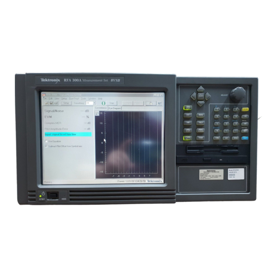
This allows you to distinguish among causes of poor signal quality. H A control for subtracting the pilot amplitude from the horizontal axis. RFA300A - - Signal / Noise & EVM Results listing Controls Figure 3- 3: S/N, EVM, and Pilot Amplitude measurement window The S/N measurement provides a broad measure of impairments in the trans- mitted signal. -
Page 48: Phase Noise 3
H Graphic showing the pilot’s phase noise spectral density measured in dBc/Hz versus frequency. The selected mask is overlaid on the display, if you enabled any in the setup (see Phase Noise Setup next). 3- 4 RFA300A Measurement Set 8VSB... -
Page 49: Figure 3- 4: Phase Noise Measurement Window
Reference RFA300A - - Phase Noise Results listing Mask indication Cursor position Cursor directions Figure 3- 4: Phase Noise Measurement window Phase Noise Setup Click the Setup button in the toolbar to enable and select a mask for the measurement window. The setup dialog box contains the control for turning masks on and off, plus a list of available masks. -
Page 50: Frequency Response And Group Delay 3
H Graphics showing frequency response measured in dB versus frequency and group delay measured in time (nanoseconds) versus frequency. Selected masks are overlaid on the display, if you enabled any in the setup (refer to Frequency Response and Group Delay Setup next). 3- 6 RFA300A Measurement Set 8VSB... -
Page 51: Figure 3- -6: Frequency Response And Group Delay Measurement
Reference RFA300A - - Frequency Response & Group Delay Results listing Mask indication Cursor position Cursor directions Figure 3- 6: Frequency Response and Group Delay measurement window Frequency Response and Click the Setup button in the toolbar to enable and select a mask for each Group Delay Setup measurement in the measurement window. -
Page 52: Amplitude And Phase Errors 3
(refer to the Glossary) and signal phase errors versus ideal signal amplitude measured in degrees versus constellation units. The selected masks are overlaid on the graphics, if enabled from the setup (refer to Amplitude and Phase Errors Setup next). 3- 8 RFA300A Measurement Set 8VSB... -
Page 53: Figure 3- 8: Amplitude And Phase Errors Measurement Window
Reference RFA300A - - Amplitude & Phase Errors Results listing Mask indication Cursor position Cursor directions Figure 3- 8: Amplitude and Phase Errors measurement window Amplitude and Phase Click the Setup button in the toolbar to enable and select masks for the measure- Errors Setup ment window. -
Page 54: Figure 3- 10: Peak-To-Average And Channel Spectrum Measurement Window
The channel spectrum is another tool to assess a transmitter’s amplitude linearity. To view this graph, click on the Channel Spectrum tab. RFA300A - - Peak / Average & Channel Spectrum Results listing Target operating point control... - Page 55 Click the Setup button in the toolbar to select the target operating point method for the measurement window. You can select in dB or percentage of time. Figure 3- -11 shows the Peak-to-Average Setup. Figure 3- 11: Peak-to-Average Setup 3- 11 RFA300A Measurement Set 8VSB...
-
Page 56: Signal Monitor 3
Limits dialog box (refer to Limits on page 2- -6). The selection of which measurements to monitor is made in the Signal Monitor Setup. Figure 3- -12 shows the Signal Monitor measurement window. RFA300A - - Amplitude & Phase Errors Figure 3- 12: Signal Monitor measurement window 3- 12... - Page 57 (see Figure 1- -10 on page 1- -15 for the alarm connection location). H How often or when to be notified. Figure 3- -13 shows the Signal Monitor Setup. Measurement selections Notification controls AutoSave controls Figure 3- 13: Signal Monitor Setup 3- 13 RFA300A Measurement Set 8VSB...
- Page 58 187-byte data block and adds 20 parity bytes. The receiver compares the 187-byte block to the 20 parity bytes to determine if the data is valid. RS encoding can correct up to 10 byte errors per one 187-byte data block (packet). 3- 14 RFA300A Measurement Set 8VSB...
- Page 59 The Trellis decoder (Viterbi) in a receiver uses the three bits to reconstruct the evolution of the data stream from one two-bit word to the next. The Trellis and Viterbi coding scheme is very effective in managing white noise. 3- 15 RFA300A Measurement Set 8VSB...
- Page 60 828 Symbols = 187 data bytes + 20 parity (R-S) bytes Symbols 1 byte 1 byte 832 Symbols = 188 byte MPEG data packet + 20 parity bytes Figure 3- 16: Data segment sync 3- 16 RFA300A Measurement Set 8VSB...
- Page 61 H Twelve symbols repeated from the previous segment. 828 Symbols Frame Sync #1 313 Segments (24.2 ms) 1 Segment = 832 Symbols = Frame Sync #2 77.3 s 313 Segments (24.2 ms) Figure 3- 17: Frame synchronizing segment 3- 17 RFA300A Measurement Set 8VSB...
-
Page 62: Closed-Loop Transmitter Control 3
A less advanced transmitter can have an open-loop precorrection system that requires manual adjustments to the controls in a shaping network to produce the corrected output. 3- 18 RFA300A Measurement Set 8VSB... -
Page 63: Appendix A: Specifications
This section lists the electrical, physical, and environmental characteristics of the RFA300A Measurement Set 8VSB. Specification Tables The tables list the specifications for the RFA300A Measurement Set 8VSB. All specifications are guaranteed unless labeled typical. Typical specifications are provided for your convenience but are not guaranteed. Specifications marked with the n symbol are checked in the Performance Verification Procedures (refer to the RFA300A Measurement Set 8VSB Service Manual). -
Page 64: Table A- 1: Input Specifications
This specification is the allowable signal amplitude of TV signals other than the one the RFA300A is to measure. It is defined as the ratio of the desired signal’s average power divided by the sync tip power of analog TV or average power of DTV signals. - Page 65 5 x 10 = 10, 762, 238 MHz Symbol Perform all calculations using the nominal value 2 ( 6 MHz ) α = – 1 = 0.1150097 Symbol Figure A- 1: IF filter characteristics A- 3 RFA300A Measurement Set 8VSB...
-
Page 66: Table A- 2: Measurement Specifications
1 dB of the correct value when S/N ≥25 dB with high smoothing. S/N Accuracy Reading is within nResidual S/N ≥40 dB . The amount of S/N that is created within the RFA300A measurement set. A- 4 RFA300A Measurement Set 8VSB... - Page 67 Note that the ratio is intentionally inverted to make the value in dB positive. EVM Accuracy 12% of the correct reading. When S/N ≥25 dB with high smoothing. nResidual EVM ≤1%. Residual EVM is created within the RFA300A measurement set. A- 5 RFA300A Measurement Set 8VSB...
- Page 68 1 dB of the correct reading. When S/N ≥25 dB with high smoothing. nResidual MER ≥40 dB. Residual MER is created within the RFA300A measurement set. (0.1 dB + 0.2 × deviation reading) dB. Pilot Amplitude Deviation When S/N ≥25 dB with high smoothing.
- Page 69 Plots the signal’s instantaneous phase error as a function of amplitude. This error is typically caused by variation of an amplifier’s phase because of signal amplitude. (5 + 0.2 × p-p degrees measured error) degree. Residual Phase Accuracy A- 7 RFA300A Measurement Set 8VSB...
- Page 70 Phase Noise ≤- - 105 dBc/Hz at 20 kHz carrier offset. This is the single sideband noise exhibited by the RFA300A local oscillator. ≤5 milliradians RMS, integrated over the range from 2 kHz to 300 kHz. Residual Phase Jitter...
-
Page 71: Table A- 3: System Components
One parallel port (printer) Two hot-pluggable keyboard ports (one on the rear panel, one on the left front side panel) Two hot-pluggable mouse ports (one on the rear panel, one on the left front side panel) A- 9 RFA300A Measurement Set 8VSB... -
Page 72: Table A- 4: Front Panel Interface Characteristics
1. Vbus 3. + data 2. - - data 4. GND Touch Panel Standard 10.4 in. touch panel pointing device mounted on the surface of the TFT display, connecting to the Front Panel Interface Board. A- 10 RFA300A Measurement Set 8VSB... -
Page 73: Table A- 5: Rear Panel Interface Characteristics
* See IEEE P1284-A in IEEE Standard 1284- - 1994 for pin connection definitions for other modes. Serial Interface Port (on back panel) 9-pin male D-sub connector RS232 Pin Assignments: 1. DCD 6. DSR 2. RXD 7. RTS 3. TXD 8. CTS 4. DTR 9. RI 5. GND A- 11 RFA300A Measurement Set 8VSB... - Page 74 3. RX+ 7. NC 4. NC 8. NC Alarm Contacts DB-9 female connector. C-form relay contacts change state upon an alarm condition Contact Ratings 28 V, 2A maximum. Pin assignments: Normally closed Common Normally open A- 12 RFA300A Measurement Set 8VSB...
-
Page 75: Table A- 6: Ac Power Source Characteristics
10 A Fast / 250 V Maximum Power Consumption 540 Watts max, 170 Watts typical Steady State Input Current 6 Amps max, 1.9 Amps RMS typical Inrush Surge Current 65 Amps maximum Power Factor Correction A- 13 RFA300A Measurement Set 8VSB... -
Page 76: Table A- 7: Environmental Characteristics
(at 50 °C or 122 °F, maximum relative humidity is ~50%). Altitude Up to 10,000 ft. (3,040m), (derated 1 °C or 1.8 °F per 1,000 ft. [305 m] above 5,000 ft. Operating [1524 m] altitude) Non-Operating 40,000 ft (12,190 m) A- 14 RFA300A Measurement Set 8VSB... -
Page 77: Table A- 8: Dynamics
Half-sine, 20 g’s, 11ms duration. 3 drops each side, 18 shocks total (no media in floppy disk drive). Table A- 9: Transportation Characteristic Description Transportation Package Material Transportation Package material meets recycling criteria as described in Environmental Guidelines for Package Design (Tektronix 063-1290-00) and Environmentally Responsible Packaging Handbook (Tektronix 063-1302-00). A- 15 RFA300A Measurement Set 8VSB... -
Page 78: Table A- 10: Certifications And Compliances
1 Compliance demonstrated using high-quality shielded interface cables. 2 EN 61326 Immunity Test requirement for Industrial Location intended use. 3 EN 61326 Minimum Immunity Test requirement. 4 Performance Criteria: Signal/Noise Ratio greater than or equal to 38 dB. A- 16 RFA300A Measurement Set 8VSB... - Page 79 Mains fuse is 10A, 250V, Fast; Not operator replaceable. Refer servicing to qualified service personnel. 80 % for temperatures up to 31 °C, decreasing linearly to 50 % at 40 °C Relative Humidity (maximum operating) A- 17 RFA300A Measurement Set 8VSB...
-
Page 80: Table A- 11: Mechanical Characteristics
60 lb (27.2 kg) Construction Materials Chassis parts are constructed of aluminum alloy and aluminized steel; front panel and trim pieces are constructed of plastic; circuit boards are constructed of glass and/or ceramic-glass laminate. A- 18 RFA300A Measurement Set 8VSB... -
Page 81: Appendix B: User Service
Appendix B: User Service This appendix describes general care and service procedures for the RFA300A Measurement Set 8VSB. Instrument and module service troubleshooting procedures are located in the service manual (refer the Preface for a list of manuals). General Care Protect the instrument from adverse weather conditions. - Page 82 Clean the face of the CD drive monthly with a cloth dampened with deionized water. CAUTION. Do not allow moisture to enter the disk drive. When power is applied, the internal components may be damaged. B- 2 RFA300A Measurement Set 8VSB...
-
Page 83: In Case Of Problems
This section does not identify specific problems relating to performance verification or adjustments. For information on running perfor- mance verification procedures or adjustment procedures, refer to the RFA300A Measurement Set 8VSB Service Manual, available as an optional accessory. -
Page 84: Table B- 1: Troubleshooting
Possible software failure or corrupted hard disk. Refer to Software Problems at the beginning of this chapter. Power-on diagnostics fail Isolate problem to faulty platform or to faulty module. Contact your local Tektronix service center. Instrument does not recognize Check that accessories are properly connected or installed. Contact your local Tektronix service accessories such as monitor, center. -
Page 85: Repackaging For Shipment
Appendix B: User Service Repackaging for Shipment Your instrument was originally shipped by Tektronix in a carton with packaging components designed to protect the instrument from damage during shipment. If you need to ship the instrument to another location, it is strongly recommended that you use the original shipping carton and packaging components to provide adequate protection during shipment. - Page 86 Appendix B: User Service Replacement Packaging New packaging materials are available from Tektronix. To obtain these items, Materials contact your nearest Tektronix representative. The replacement packaging kit, Tektronix part number 065-0651-XX, includes all of the packaging material shown in Figure B- -1. Each packaging component in the illustration has an index number, which corresponds to reference numbers in the packaging procedure.
- Page 87 NOTE. The packaging materials illustrated in Figure B- -1 will accommodate both the portable and the rackmount versions of the instrument cabinet. 1. If the instrument is to be shipped to a Tektronix field office for repair, attach a tag to the instrument showing the following: H Owner’s name and address...
- Page 88 NOTE. The packaging materials illustrated in Figure B- -2 will accommodate only the portable version of the instrument cabinet. Note: The keyboard, mouse, and manual boxes do not need to be returned with the instrument for servicing. Figure B- 2: Repackaging the instrument (old packaging) B- 8 RFA300A Measurement Set 8VSB...
- Page 89 Pack the inner shipping box as follows: 1. If an instrument is to be shipped to a Tektronix field office for repair, attach a tag to the instrument showing the following: H Owner’s name and address...
- Page 90 13. When shipping the accessories, place the two accessory trays in the top tray, then arrange the accessories in the trays. 14. Close and tape the outer shipping box (5). 15. Attach the appropriate shipping documents needed to ship the instrument to its destination. B- 10 RFA300A Measurement Set 8VSB...
-
Page 91: Overview
NOTE. If you are restoring software after replacing the hard disk drive with one you ordered as a replacement from Tektronix, follow the instructions provided with the hard disk drive replacement. If you are restoring software after reformatting the hard drive, perform all of the procedures in this section in sequence. - Page 92 H Intel EtherExpress PRO/100B PCI Adapter Driver H Touch-Base SC3 Touch Screen Driver H My- -T- -Soft NT soft keyboard H Microsoft ODBC H Microsoft Data Access Object H Tektronix RFA300A Measurement Set 8VSB application software C- 2 RFA300A Measurement Set 8VSB...
-
Page 93: Restore The Bios Settings
Boot Options The RFA300A Measurement Set 8VSB is set at the factory to boot from a removable device, CD-ROM, hard drive, and then network. If this has been changed, you must reset the boot options before you can restore the BIOS settings from the CD-ROM. -
Page 94: Restore The Contents Of The Partitions
Restore the Contents of the Partitions In some situations, such as when the power has been interrupted, or files were mistakenly deleted, the RFA300A may fail to boot from the hard drive. If this happens, use the RFA300A System and Application Restore Media CD-ROM to restore the hard drive to factory default installation status. - Page 95 Assign drive letter D: if needed. 10. From the Partition menu, select Commit Change Now. 11. From the Tools menu, select Format the new partition. Format it with the NTFS file system. C- 5 RFA300A Measurement Set 8VSB...
-
Page 96: Install And Configure Individual Components
If a component is malfunctioning, reinstall or reconfigure the driver or software individually. This may save you from having to restore the entire partition. Install ESS Technology Make sure that the RFA300A System and Application Restore Media CD-ROM is ES1869 Sound Chip Driver in the CD-ROM drive. - Page 97 Parity None Stop bits Flow control None 6. Configure COM4 as follows: Input/Output Range 02E8-02EF Interrupt Request Bits per second 9600 Data bits Parity None Stop bits Flow control None 7. Restart the system. C- 7 RFA300A Measurement Set 8VSB...
- Page 98 Appendix C: System Recovery Install the Tektronix JPS Make sure that the RFA300A System and Application Restore Media CD-ROM is Software in the CD-ROM drive. 1. From the Start menu, run E:\Drivers\Tekjps\Setup.exe. 2. Click Next in the Choose Destination Directory dialog box.
- Page 99 8. After the driver installation completes, remove the CD-ROM from the drive and restart the system. Install the Touch-Base Make sure that the RFA300A System and Application Restore Media CD-ROM is SC3 Touch-Screen Driver in the CD-ROM drive. 1. From the Start menu, run “e:\drivers\TouchBas\tnsetup.exe”.
- Page 100 8. Click Exit to exit My-T-Soft Setup. 9. Remove the CD-ROM from the drive and restart the system. Install Windows NT Make sure the RFA300A System and Application Restore Media CD-ROM is in Service Pack 5 the CD-ROM drive. 1. From the Start menu, run “e:\SP5\sp51386.exe”.
- Page 101 From the Start menu, select Setting, and then Taskbar. b. Check Auto Hide. c. Click OK. 2. Configure automatic logon (to allow the RFA300A to automatically log on when you start the system or reboot) as follows: a. From the Start menu, run E:\tools\autologon.exe (where E is the CD-ROM drive letter).
- Page 102 Appendix C: System Recovery C- 12 RFA300A Measurement Set 8VSB...
- Page 103 H A mask of the form (y, x1, x2) is one which does not necessarily have a value for all x locations. x and y numbers are in integer or scientific format. Table D- -1 lists the ResultID for each type of mask. D- 1 RFA300A Measurement Set 8VSB...
-
Page 104: Table D- 1: Resultid Values For Mask Tests
Appendix D: Mask File Formatting Table D- 1: ResultID Values for Mask Tests Mask test ResultID Frequency Response Group Delay Phase Error Phase Noise Amplitude Error Out of Channel Emissions D- 2 RFA300A Measurement Set 8VSB... - Page 105 A parameter set in the Limits dialog. When a measurement exceeds the parameter, you are notified in the measurement or Signal Monitor window. Caution limits are typically set to warn you when the measurement is close to exceeding the Alarm limit. Glossary- 1 RFA300A Measurement Set 8VSB...
- Page 106 Mask A visual parameter within the graphic portion of the measurement window against which acquired waveforms are compared. Peak Transient Power The maximum value of envelope power occasionally reached by a digitally modulated signal. Glossary- 2 RFA300A Measurement Set 8VSB...
- Page 107 Setup A collection of instrument control settings that includes measurement, monitoring, and viewing parameters. Setups do not include any option settings or system frequency selection. Glossary- 3 RFA300A Measurement Set 8VSB...
- Page 108 Glossary Glossary- 4 RFA300A Measurement Set 8VSB...
- Page 109 1- - 6 Diagnostics JSP software, C- - 8 descriptions, B- - 3 extended, 1- - 20 Display driver, C- - 6 Keyboard driver, C- - 9 Keyboard, soft, 2- - 3 Keypad, 2- - 1 Index- 1 RFA300A Measurement Set 8VSB...
- Page 110 RF connections, 1- - 14 My-T-Soft keyboard, 2- - 3 RFA300 Measurement Set 8VSB, description, 1- - 1 RFA300A software, C- - 10 My-T-Soft Keyboard driver, C- - 9 On/Standby switch, 1- - 17 Saved files, backing up, 2- - 10...
- Page 111 Sound chip driver, C- - 6 Specification, measurement, A- - 4 Specification tables, definition, A- - 1 Starting measurements, 2- - 7 Web site address, Tektronix, x Startup disks, 1- - 13 Window Stopping measurements, 2- - 7 Amplitude Error, 3- - 8...
- Page 112 Index Index- 4 RFA300A Measurement Set 8VSB...
Need help?
Do you have a question about the RFA300A and is the answer not in the manual?
Questions and answers