Advertisement
Table of Contents
- 1 Specifications
- 2 Operation and Adjustment
- 3 Maintenance and Testing
- 4 Replacement Parts
- 5 Test Button
- 6 Version Description
- 7 Operation
- 8 Filter Monitoring
- 9 Adjustment and Operation
- 10 Maintenance
- 11 Accessories and Replacement Parts
- 12 Installation
- 13 Setting and Adjustments
- 14 Auxiliary Switches
- Download this manual
UL Listed
• UL 353
• File # MH 16628
CSA Certified
• CSA C22.2 No. LR 53222
• File # 201527
FM Approved
• Class 3510, 3530
• File # J.I. 1Y9A9.AF
Commonwealth of Massachusetts
Approved Product
• Approval code G3-0106-191
• Gas pressure switch
Codes and Standards
This product is intended for installations
covered by but not limited to NFPA
85, NFPA 86, UL 795, CSD-1, ANSI
Z83.4, ANSI Z83.18, ANSI Z21.13,
and CSA B149.3.
DUNGS is an ISO 9001
manufacturing facility.
1 ... 6
Gas Pressure Switch
for DMV safety shutoff valves
GAO-A2...
GMH-A2...
GML-A2...
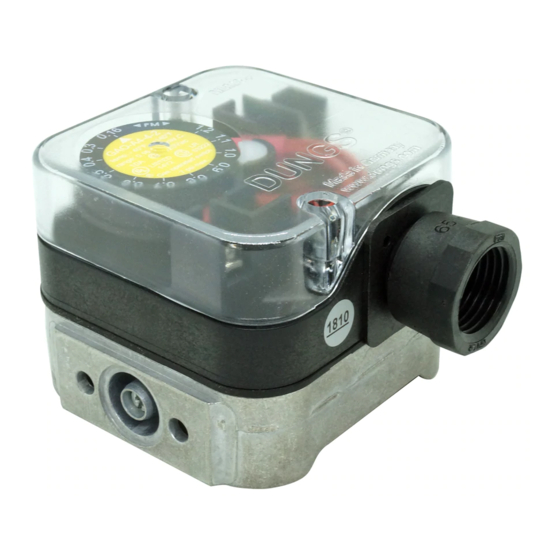
Description
The GAO-, GMH-, and GML-A2... pres-
sure switches are compact, ventless gas
pressure switches for modular valve train
components.
A2 pressure switches are suitable for
making and/or breaking a circuit when
the medium pressure changes relative
to the set point. The set point can be
set in the field by an adjustable dial with
an integrated scale. The switches incor-
porate a vent limiter as per UL 353 and
limits the escape of gas less than 1.0 CFH
of natural gas at 7 PSI if internal switch
diaphragm ruptures.
Application
The GAO-, GMH-, and GML-A2... pres-
sure switches are recommended for
industrial and commercial heating ap-
plications with DMV dual modular valves,
SV safety valves, MBC multifunctional
controls, and FRI modular pressure regu-
lators. Various mounting options allow
direct mounting on the housing.
The GAO-, GMH-, and GML-A2... pres-
sure switch is suitable for natural gas,
propane, butane, air and other inert
gases. Suitable for up to 0.1% by vol-
ume, dry H
S.
2
Advertisement
Table of Contents

Subscribe to Our Youtube Channel
Related Manuals for Dungs GAO-A2 Series


Summary of Contents for Dungs GAO-A2 Series
- Page 1 85, NFPA 86, UL 795, CSD-1, ANSI Z83.4, ANSI Z83.18, ANSI Z21.13, and CSA B149.3. Description Application DUNGS is an ISO 9001 The GAO-, GMH-, and GML-A2… pres- The GAO-, GMH-, and GML-A2… pres- manufacturing facility. sure switches are compact, ventless gas...
- Page 2 GAO-A2… SPDT pressure switch requires no auxiliary power to actuate. The GAO-A2… is suitable for making and/or breaking a circuit when the set point is exceeded or undershot. A tripped switch is indicated by a neon light after set point is exceeded or undershot.
- Page 3 Dimensions inch (mm) GAO-, GMH-, GML-A2… Slot for O-ring Adapters / replacement parts / Order No. For equipment Notes Accessories A2 Mounting kit 226-188 GAO, GMH, GML M4 Screws, 10.5 x 2.25 O-ring (included with switch) DMV & MBC Port 3 adapter (side mount 214-975 DMV-D(LE) 701 - 703 NPT 1/2“...
- Page 4 A2 mounting options FRI gas pressure regulator M o u n t i n g P r e s s u r e possible? A2 mounting options DMV 701-703 Dual modular valve Mounting P r e s s u r e possible? yes, with # 214-975 yes, horizontal...
- Page 5 A2 mounting options MBC series multifunctional control P r e s s u r e Mounting MBC ports possible? yes, with # 214-975 yes, horizontal yes, vertical with #225-047 16 12 8 16 12 8 yes, horizontal yes, vertical with #225-047 A2 mounting options SV 1005 and SV 1007 Series ports SV 1005 and SV 1007 series safety...
- Page 6 40.0 - 200.0 All switches have 120 VAC neon lights factory installed We reserve the right to make any changes in the interest of technical progress. Karl Dungs GmbH & Co. KG Karl Dungs Inc. P.O. Box 12 29 524 Apollo Drive, Suite 10 D-73602 Schorndorf, Germany Lino Lakes, MN 55014, U.S.A.
-
Page 7: Specifications
CSD-1, ANSI Z83.4, ANSI Z83.18, ANSI Z21.13, and • Ensure that the switch is not subjected to vibration during CSA B149.3. operation. Karl Dungs, Inc 524 Apollo Drive,Suite 10 Lino Lakes, MN 55014 U.S.A. 1 …6 Phone: (651) 792-8912 Fax: (651) 792-8919 E-mail: info@karldungsusa.com... - Page 8 This will be either a flange, the side of the FRI regulator, or a G 1/8 port of Dungs safety shutoff valve. • Mount the switch onto the port using the thread-forming socket head screws.
-
Page 9: Operation And Adjustment
OPERATION AND ADJUSTMENT Annually check the switch for proper operation Automatic Reset Set Point Calibration The NC contact of the GAO breaks when pressure rises The set point dial of the GAO and GMH is factory calibrated above the set point. It makes automatically when pressure with increasing pressure (GML: decreasing pressure). -
Page 10: Maintenance And Testing
MAINTENANCE AND TESTING Annually check the switch for proper operation High Gas Pressure Switch: • First, connect a meter capable of reading +/- 0 ohms to Low Gas Pressure Switch: the NC and COM contacts, and verify that the NC and •... - Page 11 MOUNTING TO SAFTY VALVES Location Model series GAO-A2-4, GMH-A2-4, and GML-A2-4 can be mounted directly to various ports on a DUNGS valve. The pressure switch should be mounted in locations meeting the requirements of the applicable code. Order mounting kit 214-975 for DMV port 3 mount and MBC port 3 mounting, and kit 225-047 for mounting switch vertically on a valve flange.
-
Page 12: Replacement Parts
MOUNTING TO SAFTY VALVES or FRI REGULATOR A2 mounting options DMV 525,5040-5125/11dual modular valve Mounting Pressure tap possible? A2 mounting options FRI gas pressure regulator M o u n t i n g Pressure tap possible? REPLACEMENT PARTS Replacement cover 228-732 (for GAO switches) and 233-113 (for GMH and GML switches) (screws not included) Screw for replacement cover... - Page 13 AA-A2… differential pressure switches Differential pressure monitoring in firing, are field adjustable, compact pressure ventilation and air-conditioning systems. DUNGS is an ISO 9001 switches for automatic burner controls. The AA-A2… can be used as a pressure, manufacturing facility. Available with hose or NPT threaded vacuum or differential pressure switch for connections.
- Page 14 AA-A2… SPDT differential pressure switch in pressure and vacuum ranges. The differential pressure acts via the diaphragm against the force of the setting spring on the microswitch. The pressure switch operates without any auxiliary power Specifications TYPE: AA-A2-4 Hose connection TYPE: AA-A2-6 Threaded connection 7 PSI (500 mbar) Max.
-
Page 15: Test Button
AA-A2-6… Threaded connection Dimensions inch (mm) Pressure connection (+) Pressure connection (–) Test nipple p (+) AA-A2-4… Hose connection 1/2” NPT 1/2” NPT Test button again and the microswitch changes to The AA-A2-6… threaded version is its original position. equipped with a test button. When the test button is pressed, the connection to the 1/4"... -
Page 16: Version Description
210-318 Male plug for DIN connector 219-659 We reserve the right to make any changes in the interest of technical progress. Karl Dungs GmbH & Co. KG Karl Dungs Inc. P.O. Box 12 29 524 Apollo Drive, Suite 10 D-73602 Schorndorf, Germany Lino Lakes, MN 55014, U.S.A. - Page 17 217-330A 0.4 - 4 AA-A2-6-5 Threaded connection 217-331A 2 - 20 AA-A2-6-6 Threaded connection 217-332A 12 - 60 Karl Dungs, Inc. 524 Apollo Drive,Suite 10 Lino Lakes, MN 55014 U.S.A. 1 …4 Phone: (651) 792-8912 Fax: (651) 792-8919 E-mail: info@karldungsusa.com...
-
Page 18: Operation
OPERATION Definition of switching hysteresis ∆p The pressure difference between the upper and lower switching pressures. Installation position: Standard installation position is vertical diaphragm. When installed horizontally, the pressure switch trips at a pressure higher by approx. 0.2 in. W.C. When installed upside down, the pressure switch switches at a pressure lower by approx. -
Page 19: Adjustment And Operation
PRESSURE CONNECTIONS AND MOUNTING AA..A2-6 AA...A2-6 Threaded Connection (1) Pressure connection (+) (2) Pressure connection (–) (3) Test nipple p (+) AA...A2-6 Mounting Procedure • Apply good quality pipe sealant to the male threads only. • Use 13/16” Wrench to secure the switch to the pipe. DO NOT Exceed 45 lb-in of Torque on 1/8”... -
Page 20: Maintenance
MAINTENANCE • Apply appressure to the + air pressure connection, and Annually check the switch for proper operation confirm that the NC contact breaks when pressure rises Set Point Calibration above the set point and that the NO contact makes. the •... - Page 21 217-330A 0.4 - 4 AA-A2-6-5 Threaded connection 217-331A 2 - 20 AA-A2-6-6 Threaded connection 217-332A 12 - 60 Karl Dungs, Inc. 524 Apollo Drive,Suite 10 Lino Lakes, MN 55014 U.S.A. 1 …4 Phone: (651) 792-8912 Fax: (651) 792-8919 E-mail: info@karldungsusa.com...
- Page 22 OPERATION Definition of switching hysteresis ∆p The pressure difference between the upper and lower switching pressures. Installation position: Standard installation position is vertical diaphragm. When installed horizontally, the pressure switch trips at a pressure higher by approx. 0.2 in. W.C. When installed upside down, the pressure switch switches at a pressure lower by approx.
- Page 23 PRESSURE CONNECTIONS AND MOUNTING AA..A2-6 AA...A2-6 Threaded Connection (1) Pressure connection (+) (2) Pressure connection (–) (3) Test nipple p (+) AA...A2-6 Mounting Procedure • Apply good quality pipe sealant to the male threads only. • Use 13/16” Wrench to secure the switch to the pipe. DO NOT Exceed 45 lb-in of Torque on 1/8”...
- Page 24 MAINTENANCE • Apply appressure to the + air pressure connection, and Annually check the switch for proper operation confirm that the NC contact breaks when pressure rises Set Point Calibration above the set point and that the NO contact makes. the •...
- Page 25 220736A,B Internal Auxiliary Switches INSTALLATION INSTRUCTIONS FEATURES • The 220736A includes one spdt Micro Switch V3 precision switch. • The 220736B includes two spdt Micro Switch V3 precision switches. • Either kit can be installed in any TRADELINE Modutrol IV motor. •...
-
Page 26: Installation
220736A,B INTERNAL AUXILIARY SWITCHES INSTALLATION 7. Position the switch assembly above the motor as shown in Fig. 1. 8. Lower the switch assembly into place and tighten the CAUTION two mounting screws, making sure the switch followers are properly aligned with the inner and outer cams in Disconnect power supply before beginning the motor. - Page 27 220736A,B INTERNAL AUXILIARY SWITCHES Table 1. Auxiliary switch leadwire colors for low and medium torque Series 91 motors with one auxiliary switch Replace with Factory-installed auxiliary switch leadwire color 220736A,B leadwire Left auxiliary switch N.O. Yellow W/Yellow Orange N.C. Blue W/Blue Purple Com.
- Page 28 220736A,B INTERNAL AUXILIARY SWITCHES Table 3. Auxiliary switch leadwire colors for all motor series except low and medium torque Series 91 (See tables 1 and 2). Replace with 220736A,B Factory-installed Auxiliary Switch Leadwire Colors Leadwire Left Auxiliary Switch N.O. Blue Blue W/Yellow Purple...
-
Page 29: Setting And Adjustments
220736A,B INTERNAL AUXILIARY SWITCHES WIRING NOTE: When the slow-rise portion of the cam is used, the switching differential is approximately 10° of rotation. When the fast-rise portion of the cam is used, the switch differential is approximately 1° of rotation. Do CAUTION not use the fast rise portion of the cam if fast cycling of auxiliary equipment is undesirable. - Page 30 220736A,B INTERNAL AUXILIARY SWITCHES M9164D1009 AND M9174D1007 ALL OTHER TRADELINE MOTORS MOVE SCREWDRIVER AT TOP ONLY TO ADJUST CAM. MOVE SCREWDRIVER AT TOP ONLY TO ADJUST CAM. RIGHT/OUTER 1/8 IN. STRAIGHT-BLADE RIGHT/INNER AUXILIARY DIVISION SCREWDRIVER AUXILIARY SWITCH (15°) SWITCH SLOW RISE SWITCH SWITCH PORTION...
- Page 31 220736A,B INTERNAL AUXILIARY SWITCHES CHECKOUT a. If contacts are open, rotate cam clockwise until N.O. contacts close. b. If contacts are closed, rotate cam counterclockwise until N.O. contacts open. WARNING 5. For switch differential of 10°, the cams must be rotated approximately 180°...
- Page 32 220736A,B INTERNAL AUXILIARY SWITCHES Automation and Control Solutions Honeywell International Inc. Honeywell Limited-Honeywell Limitée 1985 Douglas Drive North 35 Dynamic Drive Golden Valley, MN 55422 Toronto, Ontario M1V 4Z9 customer.honeywell.com ® U.S. Registered Trademark © 2009 Honeywell International Inc. 63-2228—03 K.K.
- Page 33 Stainless Steel-Case Gauge Type 1008S, ASME B 40.1 Grade B (±3-2-3% of span) • True Zero™ pointer indication – no DESIGNED FOR SAFETY AND stop pin to mask false zero reading LONGER LIFE – ensures safety and process control • Patented PowerFlex™ movement isolates movement from shock and vibration for longer life OTHER FEATURES:...
- Page 37 KECKLEY 01/06 Style B Cast Iron Y-Strainer Y-Strainer APPLICATIONS Cast Iron (ASTM A 126, Class B) Steam, water, oil or gas where protection from foreign matter in a 250 lb. Threaded pipeline is required. CONSTRUCTION The Keckley Style B strainers are constructed from rugged cast iron castings that are machined to exacting specifications.
- Page 38 KECKLEY 01/06 TECHNICAL DATA DIMENSIONS AND WEIGHTS Style B Y-Strainer, 250 lb. Threaded Cast Iron (ASTM A 126, Class B) PARTS LIST ITEM DESCRIPTION MATERIAL BODY CAST IRON (ASTM A 126, CLASS B) SCREEN STAINLESS STEEL (304) BUSHING MALLEABLE IRON GASKET* COMPOSITION CAP SCREW*...
- Page 39 O.C. Keckley Company 3400 Cleveland Street PO Box 67 Skokie, IL 60076 Toll Free Telephone: (800) 532-5539 Telephone: (847) 674-8422 Fax: Fax: (847) 674-2106 E-Mail: sales@keckley.com Web site: www.keckley.com Style B 250# threaded Cast Iron Y Strainers (CAD) KECKLEY Style B 250# threaded y-strainers are constructed from rugged cast iron castings that are machined to exacting specifications.
Need help?
Do you have a question about the GAO-A2 Series and is the answer not in the manual?
Questions and answers