
Related Manuals for VERDER JEC JRZW Series


Summary of Contents for VERDER JEC JRZW Series
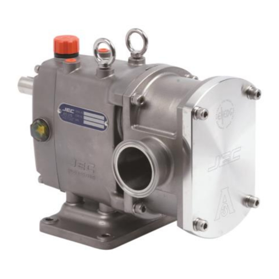
- Page 1 HYGIENIC PUMP SOLUTIONS JRZW SERIES Hygienic wine processing pump Operation and maintenance manual Find you local supplier at www.verderliquids.com...
-
Page 2: Table Of Contents
Contents Thank you for purchasing a JEC Products! This manual contains installation, operation, disassembly and assembly instructions, maintenance procedures, troubleshooting and a complete parts list for all JP series Centrifugal Pumps designed and manufactured by JEC Ltd. South Korea. READ THIS MANUAL carefully to learn how to service these pumps. Failure to do so could result in person injury or equipment damage. -
Page 7: Ce(Declaration Of Conformity)
SAFETY DO’S & DON’TS DO read and understand these instructions before installing or using the pump. DO use JEC spare parts when replacing a component of the pump. DO NOT service the pump while it is running. DO NOT place the pump in an application where the service ratings are exceed. DO NOT modify the pump. -
Page 8: Installation
INSTALLATION INSTALLATION 1. Mounting surface should be flat and level. 2. The suction line should be kept as short as possible and present minimum friction loss. 3. Suction and discharge lines must be fully supported and installed so that no expansion or shock forces act on the pump which could lead to distortion. -
Page 9: Troubleshooting
TROUBLESHOOTING Problem Cause Solution Pump not turning Interruption of electrical power Reset circuit breaker, check fuses. Key sheared or missing. Replace. Coupler or belts are not connected. Replace or adjust. Pump shaft or gears sheared. Replace. Wrong rotation. Reverse. Relief valve not properly adjusted. Adjust valve. -
Page 10: Maintenance
MAINTENANCE PUMP HOUSING DISASSEMBLY Prior to removal of pump, the shut-off valves in the suction and discharge pipe work must be closed. If there is any risk that product many harden, crystallize or freeze in the pump it should be thoroughly drained and cleaned immediately after use. Similar attention must apply to the seal flush system. -
Page 11: Disassembly
If you want replace the seal ring only, you can ease dismantle pull it off from pump housing just after removed rotors without dismantle the pump housing. And new one pushes in to pump housing. The pump housing away from the gear box. In this time, handle the shims with care to avoid lost and damage. -
Page 12: Seal Assembly
SEAL ASSEMBLY Inspect each piece of your seal replacement kit for damage before installing them. Place the pump housing face down on a table, put new seal in to the pump housing and bolts tighten. PUMP HOUSING ASSEMBLY Before install the pump housing to the gearbox make sure that cleaning on the surface of pump hosing and gear box and check to the shim plate between pump housing and gear box. -
Page 13: Rotor Clearance
ROTOR CLEALANCE Rotor clearance must be precisely maintained to provide maximum pumping efficiency, yet prevent contact between rotors, rotor housing, and front cover during operation. If pumping efficiency is below expectations, or if parts contact has occurred during operation (Within rated differential pressure), check, rotor clearances and adjust if incorrect. -
Page 14: Rotor Timing
ROTOR TIMING Rotor timing must be precisely maintained to provide maximum pumping efficiency, yet prevent contact between rotors during operation. If pumping efficiency is below expectations, or if rotors contact during operation (within rated differential pressure), check rotor timing and adjust if incorrect. Also check rotor timing after any gearbox dismantling when the gears are removed and/or replaced. -
Page 15: Shaft And Bearing Replacement
SHAFT AND BEARING REPLACEMENT Gearbox Disassembly 1. Remove the oil drain plug and drain the oil. 2. Remove the gear box cover bolts (6) from the rear cover (4). 3. Pull the rear cover off the drive shaft extension. If the cover stuck use a soft hammer carefully to loosen it. - Page 16 Gearbox Assembly 1. Clean and lubricate the front and rear bearing areas of the drive and idle shafts with oil. 2. Fit the front bearing, spacer and rear bearing on the shaft by arbor press or heat 120C (250F) up by heater. 3.
-
Page 17: Technical Information
TECHNICAL INFORMATION TECHNICAL DATA SPECIFICATIONS Maximum Inlet Pressure ----------------------------------------------- 1 bar (100 kPa, 14.5 psi) Maximum Differential Pressure ------------------------------------------ 6 bar (600 kPa, 87 psi) Maximum Flow Rate ------------------------------------------------------- 15 m3/hr (66 US GPM) ---------------------------------------- Please consult to JEC over 15 m3/hr Temperature Range ------------------------------------------------ -5 C to 120 C (23 F to 248 F) Viscosity Range -------------------------------------------------------------------------- 100,000 cPs Noise Level -------------------------------------------------------------------------------- 60 ~ 80 dB... -
Page 18: Dimensional Drawing
DIMENSIONAL DRAWING... -
Page 19: Parts List
Parts list EXPLODED VIEW... - Page 20 All orders for repair parts must contain the following; 1. Complete model number (located on nameplate). 2. Pump serial number (located on nameplate). 3. Description and part number from the parts list. Please refer the ‘Parts list’ separately for further reference. Q'ty ITEM PART NO.
- Page 21 Q'ty ITEM PART NO. Description Material Ass'y Pump ZL10-GB02-A1 Gear Box Ass'y - White FCD40 ZL10-GB02-A2 Gear Box Ass'y – Silver FCD40 ZL10-GB02-A3 Gear Box Ass'y - Stainless Steel SUS304 ZW10-RC01-SS Rotor Case SUS316L ZL10-FC03-SS Front Cover SUS316L ZL10-CN01-SS Cap Nut SUS304 ZL10-OR09-L1 O-ring, Front Cover (AN251)
-
Page 22: Single/Double Mechanical Seal
Single/Double mechanical seal Single mechanical seal Double mechanical seal Q'ty ITEM PART NO. Description Material Ass'y Pump ZL10-FW01-SS Flat Washer, M/Seal Gland (Φ6) SUS304 ZL10-WB04-SS Wrench Bolt, M/Seal Gland (M6x10L) SUS304 ZW10-OR03-L1 O-ring, Rotor (AN027) EPDM 52-2 ZW10-OR03-L2 O-ring, Rotor (AN027) ZW10-OR03-L3 O-ring, Rotor (AN027) Perfluoro... - Page 23 Q'ty ITEM PART NO. Description Material Ass'y Pump ZL10-SE02-S1 Double Seal Body, Case TC/SUS304 ZL10-SE02-S2 Double Seal Body, Case SiC/SUS304 ZL10-OR06-L1 O-ring, Case, Double seal (AN036) EPDM ZL10-OR06-L2 O-ring, Case, Double seal (AN036) ZL10-OR06-L3 O-ring, Case, Double seal (AN036) Perfluoro ZL10-SE01-C Rotation part, Double Seal, Shaft Carbon/SUS304...
Need help?
Do you have a question about the JEC JRZW Series and is the answer not in the manual?
Questions and answers