Table of Contents
Advertisement
Quick Links
INSTRUCTIONS - PARTS LIST
This manual contains important
warnings and information.
READ AND RETAIN FOR REFERENCE
INSTRUCTIONS
VERDERAIR VA 8 Air-Operated
Diaphragm Pumps
0.7 MPa, 7 bar Maximum Incoming Air Pressure
0.7 MPa, 7 bar Maximum Fluid Working Pressure
* NOTE: Refer to the pump listing on page to determine the Model No of your pump.
Patent Pending
Contents
. . . . . . . . . . . . . . . . . . . . . . . . . . . . . . . . . . . . . . . . . .
. . . . . . . . . . . . . . . . . . . . . . . . . . . . . . . . . . . . . . . . .
. . . . . . . . . . . . . . . . . . . . . . . . . . . . . . . . . . . . . . . . . .
. . . . . . . . . . . . . . . . . . . . . . . . . . . . . . . . . . . . . . . .
. . . . . . . . . . . . . . . . . . . . . . . . . . . . . . . . . . . . .
. . . . . . . . . . . . . . . . . . . . . . . . . . . . . . . . . . . . . . . . . . .
. . . . . . . . . . . . . . . . . . . . . . . . . . . . . . . . . . . . . . .
. . . . . . . . . . . . . . . . . . . . . . . . . . . . . . . . . .
. . . . . . . . . . . . . . . . . . . . . . . . . . . . . . . . . . . . . . . . .
. . . . . . . . . . . . . . . . . . . . . . . . . . . . . . . . . . . . . .
. . . . . . . . . . . . . . . . . . . . . . . . . . . . . . . . . . .
. . . . . . . . . . . . . . . . . . . . . . . . . . . . . . . . . . . . .
. . . . . . . . . . . . . . . . . . . . . . . . . . . . . . . .
. . . . . . . . . . . . . . . . . . . . . . . . . . . . . . . .
Parts
2
4
7
8
9
11
14
14
15
16
17
19
. . . . . . . . . . . . . . . .
19
20
22
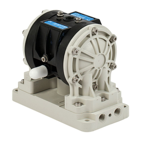
Model 810.6012
shown
819.6247
Rev. R
06176
Advertisement
Table of Contents

Related Manuals for VERDER AIR VA 8 810.6012


Summary of Contents for VERDER AIR VA 8 810.6012
-
Page 1: Table Of Contents
Parts INSTRUCTIONS - PARTS LIST This manual contains important 819.6247 warnings and information. READ AND RETAIN FOR REFERENCE INSTRUCTIONS Rev. R VERDERAIR VA 8 Air-Operated Diaphragm Pumps 0.7 MPa, 7 bar Maximum Incoming Air Pressure 0.7 MPa, 7 bar Maximum Fluid Working Pressure * NOTE: Refer to the pump listing on page to determine the Model No of your pump. -
Page 2: Warnings
If you are not sure, or if you have questions about installation or operation, call your VERDER distributor. D Never alter or modify any part of this equipment; doing so could cause it to malfunction. - Page 3 Warning HAZARDOUS FLUIDS Improper handling of hazardous fluids or inhaling toxic vapors can cause extremely serious injury or death from splashing in the eyes, ingestion, or bodily contamination. Observe all the following precautions when you handle hazardous or potentially hazardous fluids. D Know what fluid you are pumping and its specific hazards.
-
Page 4: Installation
Installation Tightening Threaded Fasteners Before First Place the nut in the nut catcher on the underside of the manifold. Insert the bolt through the loop end of the ground wire. After unpacking the pump, and before using it for the first time, check and retorque all external fasteners. - Page 5 Installation Install a bleed-type master air valve downstream Mountings from the air regulator, and use it to relieve trapped air. See the Bleed-Type Master Air Valve and Caution Fluid Drain Valve warning at left. Locate another bleed-type master air valve upstream from all air line The pump exhaust air may contain contaminants.
- Page 6 The installation shown in Fig. 3 is only a guide to help select and install a pump; they are not actual system designs. Caution Typical installation includes (not supplied by VERDER): D For solenoid operation: four-way, 5-port, 2-position sole- For solenoid operation, the pump must exhaust through the noid valve with 1/4-in.
-
Page 7: Operation
Operation Place the suction tube (if used) in the fluid to be pumped. Pressure Relief Procedure Place the end of the outlet hose into an appropriate con- Warning tainer. Close the fluid drain valve. To reduce the risk of serious injury, including splashing fluid in the eyes or on the skin, follow this procedure whenever With the air regulator closed, open all bleed-type master you are instructed to relieve pressure, when you shut off... -
Page 8: Maintenance
Maintenance Lubrication Flushing and Storage The air valve is lubricated at the factory and designed to op- Flush the pump to prevent the fluid from drying or freezing in erate without additional lubrication. the pump and damaging it. Always flush the pump and re- If added lubrication is desired, every 500 hours of operation lieve the pressure before storing for any length of time. -
Page 9: Troubleshooting
Troubleshooting Relieve the pressure before you check or service the equip- Warning ment. Check all possible problems and causes before you disas- To reduce the risk of serious injury whenever you are semble the pump. instructed to relieve pressure, always follow the Pressure Relief Procedure on page 7. - Page 10 Troubleshooting Internal Air Valve-Operated Pumps Only PROBLEM CAUSE SOLUTION The pump will not cycle, or it cycles The air valve is stuck or dirty. Disassemble and clean or repair the air. once and stops. Use filtered air. Increase air pressure supply. Do not ex- Not enough air pressure supplied.
-
Page 11: Service
Service Remove the four screws (14) that hold the valve Service Kits cover (7) on the center housing (1). Service Kits may be ordered separately. Remove the valve block (4) and valve carriage (2), and replace the u-cups (3). Replace the valve carriage and To repair the air valve, order Part No. - Page 12 Service Replacing Diaphragms Remove the diaphragm pins (8), remove and replace the o-rings (9), and reinstall the diaphragm pins in the center Replace the diaphragms as follows. See Fig. 5 and Fig. 6. housing (1). Relieve the pressure, and disconnect the air line from the pump.
- Page 13 Service Replacing Check Valves Replace each pair of check valves as follows. See Fig. 6. Relieve the pressure, and disconnect the air line from the pump. Warning To reduce the risk of serious injury whenever you are instructed to relieve pressure, always follow the Pressure Relief Procedure on page 7.
-
Page 14: Parts Listing
Parts Listing VERDERAIR VA 8 Polypropylene, Acetal, and Kynarr Pumps, Series B Your Model No. is marked on the pump’s serial plate. The listing of existing VERDERAIR VA 8 pumps is below: Standard operation For Solenoid Operation Seats Seats Fluid Fluid Ref. -
Page 15: Parts Lists
Parts Air Motor Section Fluid Ref. Section Ref. Part No. Description Qty. Material Part No. Description Qty. 819.6900 HOUSING, center 819.7019 COVER, fluid; acetal 819.6252 CARRIAGE, valve 819.7020 MANIFOLD; acetal 819.6860 SEAL, u-cup 819.6272 PLUG, port; acetal 819.6901 VALVE BLOCK (for pump with 819.0186 SCREW, grounding air-operated air motor) -
Page 16: Parts Drawing
Parts Check Valve Check Check Valve Valve Ref. Ref. Material Part No. Description Qty. Material Part No. Description Qty. 819.7027 VALVE, check; acetal 819.7029 VALVE, check; KynarR 4 819.6262 O-RING, packing 819.6262 O-RING, packing 819.7028 VALVE, check; polypropylene Diaphragm Ref. Part No. -
Page 17: Torque Sequence
Torque Sequence For proper installation, always follow torque sequence whenever you are instructed to torque screws. 1. Valve Cover 2. Left/Right Fluid Cover 3. Manifold to Center Section 11, 19 12, 20 Back View Front View 819.6247... - Page 18 18 819.6247...
-
Page 19: Technical Data
Technical Data Maximum fluid working pressure ....100 psi Weight 0.7 MPa (7 bar) Polypropylene pump ....2.0 lb (0.9 kg) Maximum/minimum air pressure . -
Page 20: Performance Charts
Performance Charts VERDERAIR VA 8 Fluid Outlet Pressure Test Conditions: Pump tested in water with inlet submerged. (0.7, 7) Fluid Pressure Curves at 100 psi (0.7 MPa, 7 bar) air pressure (0.62, 6.2) at 70 psi (0.48 MPa, 4.8 bar) air pressure at 40 psi (0.28 MPa, 2.8 bar) air pressure (0.55, 5.5) (0.48, 4.8) - Page 21 Performance Charts VERDERAIR VA 8 Air Consumption Test Conditions: Pump tested in water with inlet submerged. (0.17) (0.14) Air Consumption Curves at 100 psi (0.7 MPa, 7 bar) air pressure at 70 psi (0.48 MPa, 4.8 bar) air pressure at 40 psi (0.28 MPa, 2.8 bar) air pressure (0.11) (0.09) (0.06)
-
Page 22: Customer/Guarantee
GUARANTEE All VERDER pumps are warranted to the original user against defects in workmanship or materials under normal use (rental use excluded) for two years after purchase date. This warranty does not cover failure of parts or components due to normal wear, damage or failure which in the judgement of VERDER arises from misuse. - Page 23 94/9/EC ATEX Directive (Ex II 2 G EEx c IIA T6) EN 292 EN 1127–1 EN 13463–1 ISO 9614–1 0359 12January2005 Frank Meersman 12January2005 DIRECTOR (Print) Verder Ltd. Whitehouse street Part No. : 819.6317 Leeds LS10 1AD Great Britain 819.6247...
- Page 24 Austria Germany Poland VERDER Ges. mbH Austria VERDER Deutschland GmbH VERDER Polska Sp. z o.o Perfektasstrasse 86 Rheinische Straße 43 ul. Kamienskiego 201-219 A-1232 Wien PO Box 1739 PL-51-124 Wroclaw, Polska Tel. 0222-8651074-0 D-42781 Haan Tel. 0 71726158 w.e.w. 59 Fax 0222-8651076 Tel.
Need help?
Do you have a question about the AIR VA 8 810.6012 and is the answer not in the manual?
Questions and answers