
Related Manuals for VERDER JEC JRZLF Series


Summary of Contents for VERDER JEC JRZLF Series
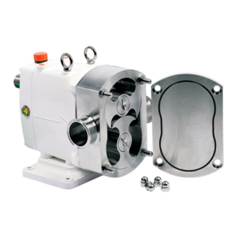
- Page 1 HYGIENIC PUMP SOLUTIONS JRZLF SERIES Hygienic rotary lobe pumps with front bearing cover Operation and maintenance manual Find you local supplier at www.verderliquids.com...
-
Page 2: Table Of Contents
Contents Thank you for purchasing JEC Products! This manual contains installation, operation, disassembly and assembly instructions, maintenance procedures, troubleshooting and a complete parts list for all JP series Centrifugal Pumps designed and manufactured by JEC Ltd. South Korea. READ THIS MANUAL carefully to learn how to service these pumps. Failure to do so could result in person injury or equipment damage. -
Page 8: Ce (Declaration Of Conformity)
SAFETY DO’S & DON’TS DO read and understand these instructions before installing or using the pump. DO use JEC spare parts when replacing a component of the pump. DO NOT services the pump while it is running. DO NOT place the pump in an application where the service ratings are exceed. DO NOT modifies the pump. -
Page 9: Installation
INSTALLATION INSTALLATION 1. Mounting surface should be flat and level. 2. The suction line should be kept as short as possible and present minimum friction loss. 3. Suction and discharge lines must be fully supported and installed so that no expansion or shock forces act on the pump which could lead to distortion. -
Page 10: Troubleshooting
TROUBLESHOOTING Problem Cause Solution Pump not turning Interruption of electrical power. Reset circuit breaker, check fuses. Key sheared or missing. Replace. Coupler or belts are not connected. Replace or adjust. Pump shaft or gears sheared. Replace. Wrong rotation. Reverse. Relief valve not properly adjusted. Adjust valve. -
Page 11: Maintenance
MAINTENANCE PUMP HOUSING DISASSEMBLY This JRZLF series with front bearing cover high pressure application has a same design and structure with JRZL series, except bearing applied front cover. Therefore, except the maintenance for front cover side, all of procedure is same as standard rotary pump. - Page 12 Note: JRZLF series has different screw thread for drive and idle shafts. (but ZL series has same screw thread for CW: tightening, CCW: loosening) The standard screw thread is CCW for loosening, and CW for tightening for drive shaft. But please check pump specification before maintenance because based on flow direction, extended shaft thread could be changed too.
- Page 13 Remove the four stud bolt securing the pump housing to the gearbox. Figure 7 Figure 8 Slide the pump housing away from the gear box. In this time, handle the shim(s) with care to avoid lost and damage. If the housing is stuck, alternately tap on the back of the inlet and outlet ports with a soft hammer.
-
Page 14: Inspection
If you want replace the seal ring only, you can ease dismantle pull it off from pump housing just after removed rotors without dismantle the pump housing. And new one pushes in to pump housing. The seal ring can be easily removed from rotor with small screw driver (-) or a pin as shown in Figure 13. -
Page 15: Seal Assembly
Seal Assembly Inspect each piece of your seal replacement kit for damage before installing them. Place the pump housing face down on a table, put new seal in to the pump housing and bolts tighten. (Figure 16, 17) Figure 16 Figure 17 Pump Housing Assembly Before install the pump housing to the gearbox make sure that cleaning on the surface of... -
Page 16: Rotor Clearance
Rotor Clearance Rotor clearance must be precisely maintained to provide maximum pumping efficiency, yet prevent contact between rotors, rotor housing, and front cover during operation. If pumping efficiency is below expectations, or if parts contact has occurred during operation (Within rated differential pressure), check, rotor clearances and adjust if incorrect. -
Page 17: Rotor Timing
Rotor Timing Rotor timing must be precisely maintained to provide maximum pumping efficiency, yet prevent contact between rotors during operation. If pumping efficiency is below expectations, or if rotors contact during operation (within rated differential pressure), check rotor timing and adjust if incorrect. Also check rotor timing after any gearbox dismantling when the gears are removed and/or replaced. -
Page 18: Shaft And Bearing Replacement
Shaft and Bearing Replacement Gearbox Disassembly 1. Remove the oil drain plug and drain the oil. 2. Remove the gear box cover bolts (33) from the gear box cover (2). 3. Pull the gear box cover off the drive shaft extension. If the cover stuck use a soft hammer carefully to loosen it. - Page 19 Gearbox Assembly 1. Clean and lubricate the front and rear bearing areas of the drive and idle shafts with oil. 2. Fit the front bearing, spacer and rear bearing on the shaft by arbor press or heat 120C (250F) up by heater. 3.
-
Page 20: Technical Information
TECHNICAL INFORMATION TECHNICAL DATA SPECIFICATIONS Maximum Inlet Pressure ---------------------------------------------- 10 bar (1,000 kPa, 145 psi) Maximum Differential Pressure --------25 bar (363psi) is available with ‘Front bearing cover’ Maximum Flow Rate ----------------------------------------------------- 100 m3/hr (440 US GPM) ------------------ Please consult to JEC over 100 m3/hr up to 450 m3/hr Temperature Range ----------------------------------------------- -10 C to 180 C (14 F to 356 F) Viscosity Range ------------------------------------------------------------------------ 1,000,000 cPs Noise Level -------------------------------------------------------------------------------- 60 ~ 80 dB... -
Page 21: Dimensional Drawing
DIMENSIONAL DRAWING Dimension (mm) Model No. ZLF120-021-21 ZLF220-040-25 ZLF225-062-21 ZLF330-102-25 243.5 128.5 ZLF340-144-21 243.5 128.5 ZLF440-227-25 ZLF450-334-21 ZLF560-700-12 ZLF580-1000-08 ZLF5100-1200-06 1014 Dimension B1 (mm) Weight Volume Model No. Ports FLANGE ZLF120-021-21 2” 0.01 ZLF220-040-25 2” 0.03 ZLF225-062-21 2 1/2” 0.03 ZLF330-102-25 3”... -
Page 22: Parts List
PARTS LIST EXPLODED VIEW / ZLF120, ZLF200 and ZLF300... -
Page 23: Part List / Zlf120, Zlf200 And Zlf300
All orders for repair parts must be contained the following; 1. Complete model number (located on nameplate). 2. Pump serial number (located on nameplate). 3. Description and part number from the parts list. Please refer the ‘Parts list’ separately for further reference. Parts list / ZLF120 Q'ty ITEM... - Page 24 Q'ty ITEM PART NO. Description Material Ass'y Pump ZLF120-GBXH-CW Gear Box Ass'y - White FCD40 ZLF120-GBXH-CS Gear Box Ass'y - Silver FCD40 ZLF120-GBXH-SS Gear Box Ass'y - Stainless Steel SUS304 PCZL-M08X-SS Cap Nut SUS304 PCOR-A251-NB O-ring, Front Cover (AN251) PCOR-A251-EP O-ring, Front Cover (AN251) EPDM PCOR-A251-FP...
- Page 25 Q'ty ITEM PART NO. Description Material Ass'y Pump MMZF-120D-SS Rotor Case-2"DIN11851 SUS316L MMZF-120F-SS Rotor Case-2"DIN2633(FLANGE) SUS316L MMZF-120S-SS Rotor Case-2"DS722.1 SUS316L MMZF-120I-SS Rotor Case-2"ISOMALE(IDF) SUS316L MMZF-120R-SS Rotor Case-2"RJT SUS316L MMZF-120M-SS Rotor Case-2"SMS SUS316L MMZF-120C-SS Rotor Case-2"TRICLAMP SUS316L MMZF-120K-SS Rotor Case-2"FLANGE SUS316L MMZF-SW1B-SS Rotor, Single-Wing SUS316L...
- Page 26 SINGLE MECHANICAL SEAL Q'ty ITEM PART NO. Description Material Ass'y Pump PCFW-P06X-SS Flat Washer, M/Seal Gland (Φ6) SUS304 PCWB-M06A-SS Wrench Bolt, M/Seal Gland (M6x10L) SUS304 PCOR-A028-NB O-ring, Rotor (AN028) PCOR-A028-EP O-ring, Rotor (AN028) EPDM PCOR-A028-FP O-ring, Rotor (AN028) PMOR-A028-PF O-ring, Rotor (AN028) Perfluoro PMZL-SR1X-TC Seal Ring...
- Page 27 DOUBLE MECHANICAL SEAL Q'ty ITEM PART NO. Description Material Ass'y Pump PCOR-A028-NB O-ring, Rotor (AN028) PCOR-A028-EP O-ring, Rotor (AN028) EPDM PCOR-A028-FP O-ring, Rotor (AN028) PMOR-A028-PF O-ring, Rotor (AN028) Perfluoro PMZL-SR1X-TC Seal Ring PMZL-SR1X-SI Seal Ring PCOR-A220-NB O-ring, Rotor Case (AN220) PCOR-A220-EP O-ring, Rotor Case (AN220) EPDM...
- Page 28 All orders for repair parts must be contained the following; 1. Complete model number (located on nameplate). 2. Pump serial number (located on nameplate). 3. Description and part number from the parts list. Please refer the ‘Parts list’ separately for further reference. Parts list / ZLF200 Q'ty ITEM...
- Page 29 Q'ty ITEM PART NO. Description Material Ass'y Pump ZLF220-GBXH-CW Gear Box Ass'y - White, ZLF220 FCD40 ZLF220-GBXH-CS Gear Box Ass'y - Silver, ZLF220 FCD40 ZLF220-GBXH-SS Gear Box Ass'y - Stainless Steel, ZLF220 SUS304 ZLF225-GBXH-CW Gear Box Ass'y - White, ZLF225 FCD40 ZLF225-GBXH-CS Gear Box Ass'y - Silver, ZLF225...
- Page 30 Q'ty ITEM PART NO. Description Material Ass'y Pump MMZL-BBC2-SS Bearing Block Cover, High Pressure SUS304 PCWB-M08C-SS Wrench Bolt, M8x40L SUS304 PMHN-M08L-SS Lock Nut, M8 SUS304 PMZL-LB09-SS Bush, Lock Nut, Ø 13xØ 9x13 SUS304 PCWB-M08G-SS Wrench Bolt, M8x30L SUS304 PCWB-M08H-SS Wrench Bolt, M8x35L SUS304 Note: 1.
- Page 31 Q'ty ITEM PART NO. Description Material Ass'y Pump MMZF-220D-SS Rotor Case-2"DIN11851, ZLF220 SUS316L MMZF-220F-SS Rotor Case-2"DIN2633(FLANGE), ZLF220 SUS316L MMZF-220S-SS Rotor Case-2"DS722.1, ZLF220 SUS316L MMZF-220I-SS Rotor Case-2"ISOMALE(IDF), ZLF220 SUS316L MMZF-220R-SS Rotor Case-2"RJT, ZLF220 SUS316L MMZF-220M-SS Rotor Case-2"SMS, ZLF220 SUS316L MMZF-220C-SS Rotor Case-2"TRICLAMP, ZLF220 SUS316L MMZF-220K-SS Rotor Case-2"FLANGE, ZLF220...
- Page 32 SINGLE MECHANICAL SEAL Q'ty ITEM PART NO. Description Material Ass'y Pump PCFW-P06X-SS Flat Washer, M/Seal Gland (Φ6) SUS304 PCWB-M06A-SS Wrench Bolt, M/Seal Gland (M6x10L) SUS304 PCOR-A031-NB O-ring, Rotor (AN031) PCOR-A031-EP O-ring, Rotor (AN031) EPDM PCOR-A031-FP O-ring, Rotor (AN031) PMOR-A031-PF O-ring, Rotor (AN031) Perfluoro PMZL-SR2X-TC Seal Ring...
- Page 33 DOUBLE MECHANICAL SEAL Q'ty ITEM PART NO. Description Material Ass'y Pump PCOR-A031-NB O-ring, Rotor (AN031) PCOR-A031-EP O-ring, Rotor (AN031) EPDM PCOR-A031-FP O-ring, Rotor (AN031) PMOR-A031-PF O-ring, Rotor (AN031) Perfluoro PMZL-SR2X-TC Seal Ring PMZL-SR2X-SI Seal Ring PCOR-A225-NB O-ring, Rotor Case (AN225) PCOR-A225-EP O-ring, Rotor Case (AN225) EPDM...
- Page 34 All orders for repair parts must be contained the following; 1. Complete model number (located on nameplate). 2. Pump serial number (located on nameplate). 3. Description and part number from the parts list. Please refer the ‘Parts list’ separately for further reference. Parts list / ZLF300 Q'ty ITEM...
- Page 35 Q'ty ITEM PART NO. Description Material Ass'y Pump ZLF330-GBXH-CW Gear Box Ass'y - White, ZLF330 FCD40 ZLF330-GBXH-CS Gear Box Ass'y - Silver, ZLF330 FCD40 ZLF330-GBXH-SS Gear Box Ass'y - Stainless Steel, ZLF330 SUS304 ZLF340-GBXH-CW Gear Box Ass'y - White, ZLF340 FCD40 ZLF340-GBXH-CS Gear Box Ass'y - Silver, ZLF340...
- Page 36 Q'ty ITEM PART NO. Description Material Ass'y Pump MMZL-BBC3-SS Bearing Block Cover, High Pressure SUS304 PCWB-M10I-SS Wrench Bolt, M10x50L SUS304 PMHN-M10L-SS Lock Nut, M10 SUS304 PMZL-LB11-SS Bush, Lock Nut, Ø 16x12 SUS304 PCWB-M10F-SS Wrench Bolt, M10x40L SUS304 PCWB-M10G-SS Wrench Bolt, M10x60L SUS304 Note: 1.
- Page 37 Q'ty ITEM PART NO. Description Material Ass'y Pump MMZF-330D-SS Rotor Case-3"DIN11851, ZLF330 SUS316L MMZF-330F-SS Rotor Case-3"DIN2633(FLANGE), ZLF330 SUS316L MMZF-330S-SS Rotor Case-3"DS722.1, ZLF330 SUS316L MMZF-330I-SS Rotor Case-3"ISOMALE(IDF), ZLF330 SUS316L MMZF-330R-SS Rotor Case-3"RJT, ZLF330 SUS316L MMZF-330M-SS Rotor Case-3"SMS, ZLF330 SUS316L MMZF-330C-SS Rotor Case-3"TRICLAMP, ZLF330 SUS316L MMZF-330K-SS Rotor Case-3"...
- Page 38 SINGLE MECHANICAL SEAL Q'ty ITEM PART NO. Description Material Ass'y Pump PCFW-P06X-SS Flat Washer, M/Seal Gland (Φ6) SUS304 PCWB-M06A-SS Wrench Bolt, M/Seal Gland (M6x10L) SUS304 PCOR-A142-NB O-ring, Rotor (AN142) PCOR-A142-EP O-ring, Rotor (AN142) EPDM PCOR-A142-FP O-ring, Rotor (AN142) PMOR-A142-PF O-ring, Rotor (AN142) Perfluoro PMZL-SR3C-TC Seal Ring...
- Page 39 DOUBLE MECHANICAL SEAL Q'ty ITEM PART NO. Description Material Ass'y Pump PCOR-A142-NB O-ring, Rotor (AN142) PCOR-A142-EP O-ring, Rotor (AN142) EPDM PCOR-A142-FP O-ring, Rotor (AN142) PMOR-A142-PF O-ring, Rotor (AN142) Perfluoro PMZL-SR3C-TC Seal Ring PMZL-SR3C-SI Seal Ring PCOR-A230-NB O-ring, Rotor Case (AN230) PCOR-A230-EP O-ring, Rotor Case (AN230) EPDM...
-
Page 40: Exploded View / Zlf400
EXPLODED VIEW / ZLF400... -
Page 41: Part List / Zlf400
All orders for repair parts must be contained the following; 1. Complete model number (located on nameplate). 2. Pump serial number (located on nameplate). 3. Description and part number from the parts list. Please refer the ‘Parts list’ separately for further reference. Parts list / ZLF400 Q'ty ITEM... - Page 42 Q'ty ITEM PART NO. Description Material Ass'y Pump ZLF440-GBXH-CW Gear Box Ass'y - White, ZLF440 FCD40 ZLF440-GBXH-CS Gear Box Ass'y - Silver, ZLF440 FCD40 ZLF440-GBXH-SS Gear Box Ass'y - Stainless Steel, ZLF440 SUS304 ZLF450-GBXH-CW Gear Box Ass'y - White, ZLF450 FCD40 ZLF450-GBXH-CS Gear Box Ass'y - Silver, ZLF450...
- Page 43 Q'ty ITEM PART NO. Description Material Ass'y Pump MMZF-BC40-SS Bearing Block Cover, High Pressure SUS304 PCWB-M10G-SS Wrench Bolt, M10x60L SUS304 PMHN-M10L-SS Lock Nut, M10 SUS304 PMZL-LB11-SS Bush, Lock Nut, Ø 15xØ 11x13 SUS304 PCWB-M12D-SS Wrench Bolt, M12x40L SUS304 PCWB-M12E-SS Wrench Bolt, M12x80L SUS304 Note: 1.
- Page 44 Q'ty ITEM PART NO. Description Material Ass'y Pump MMZF-440D-SS Rotor Case-4"DIN11851, ZLF440 SUS316L Rotor Case-4"DIN2633(FLANGE), MMZF-440F-SS SUS316L ZLF440 MMZF-440S-SS Rotor Case-4"DS722.1, ZLF440 SUS316L MMZF-440I-SS Rotor Case-4"ISOMALE(IDF), ZLF440 SUS316L MMZF-440R-SS Rotor Case-4"RJT, ZLF440 SUS316L MMZF-440M-SS Rotor Case-4"SMS, ZLF440 SUS316L MMZF-440C-SS Rotor Case-4"TRICLAMP, ZLF440 SUS316L MMZF-440K-SS Rotor Case-4"...
- Page 45 SINGLE MECHANICAL SEAL Q'ty ITEM PART NO. Description Material Ass'y Pump PCFW-P06X-SS Flat Washer, M/Seal Gland (Φ6) SUS304 PCWB-M06A-SS Wrench Bolt, M/Seal Gland (M6x10L) SUS304 PCOR-A151-NB O-ring, Rotor (AN151) PCOR-A151-EP O-ring, Rotor (AN151) EPDM PCOR-A151-FP O-ring, Rotor (AN151) PMOR-A151-PF O-ring, Rotor (AN151) Perfluoro PMZL-SR4X-TC Seal Ring...
- Page 46 DOUBLE MECHANICAL SEAL Q'ty ITEM PART NO. Description Material Ass'y Pump PCOR-A151-NB O-ring, Rotor (AN151) PCOR-A151-EP O-ring, Rotor (AN151) EPDM PCOR-A151-FP O-ring, Rotor (AN151) PMOR-A151-PF O-ring, Rotor (AN151) Perfluoro PMZL-SR4X-TC Seal Ring PMZL-SR4X-SI Seal Ring PCOR-A235-NB O-ring, Rotor Case (AN235) PCOR-A235-EP O-ring, Rotor Case (AN235) EPDM...
- Page 47 JEC LTD. All technical information and its contents contained in this manual is subject to change without prior notice and does not represent a commitment on the part of JEC Ltd. Any part of this manual may 15-26, Beodeul-ro, Paltan-myun, Hwaseong-si, NOT be reproduced, copied, duplicated or transmitted in any form or by any means, electronic or mechanical, photocopying, Gyeonggi-do, 18578, Rep.
Need help?
Do you have a question about the JEC JRZLF Series and is the answer not in the manual?
Questions and answers