Subscribe to Our Youtube Channel
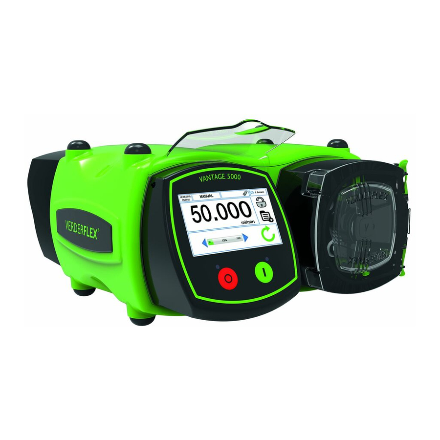
Summary of Contents for VERDER Verderflex Vantage 5000
- Page 1 Peristaltic Cased Tube Pump Appendix F Breakout Box Vantage 5000 Version 1.6v-05/2019 Print-No.
- Page 2 Vantage 5000 Version 1.6v-05/2019 Print-No. 01 Appendix F 1.6v-05.2019 2 | Page...
-
Page 3: Table Of Contents
Table of contents Appendix F Breakout Box Installing the Breakout Box 1.1.1 Parts for Reference 1.1.2 Installation Instructions Functionality Voltage Supplies Applied Voltage Signals ‘Volt-free’ Signals Output Signals Analogue signals Appendix F 1.6v-05.2019 3 | Page... -
Page 4: Appendix F Breakout Box
Appendix F Breakout Box The breakout box has been provided to allow the user to make easy connections to all the remote input/output lines on the 25 WAY Remote I/O Connector on the back of the Vantage 5000. For the connector number’s function of the 24VDC breakout box, see Table 1 and the 115VAC breakout box, see Table 2. - Page 5 The following table shows the Vantage 5000 description of connector numbers on the 25 WAY Remote I/O Connector that are provided with the 24VDC breakout box. Connector Number Function Type Pin number Signal START Input +24V Relay Supply 0V Relay Supply MANUAL/AUTO Input +24V Relay Supply...
- Page 6 The following table shows the Vantage 5000 description of connector numbers on the 25 WAY Remote I/O Connector that are provided with the 115VAC breakout box. Connector Number Function Type Pin number Signal START Input 115V Relay Supply 115V Relay Supply MANUAL/AUTO Input 115V Relay Supply...
-
Page 7: Installing The Breakout Box
Installing the Breakout Box 1.1.1 Parts for Reference Item Image 24 VDC Breakout Box 115 VAC Breakout Board M4 x 8 Fixing Assembly Gland Blanking Plugs with Retaining Nuts Bulkhead Cable Glands with Retaining Nuts 5.6 mm x 4-40 UNC D Type Connector Fix- ing Screws Breakout Box Fix- M5 x 12... -
Page 8: Installation Instructions
1.1.2 Installation Instructions Note The following installation instructions images relate to interfac- ing a remote start/stop cable connection via a 24VDC breakout board powered from the local 24VDC supply of the Vantage 5000. Remove the four M4 x 8 breakout board fixing screws to release the board from the breakout box. Wire up the breakout board as required;... -
Page 9: Functionality
Functionality The following table shows the Vantage 5000 features on the 25 WAY Remote I/O Connector that are provided with the breakout box. Voltage Supplies Maximum power supply for 24VDC & 115VAC version of Breakout box is +/- 10%. Function Connector Description Graphic... -
Page 10: Applied Voltage Signals
Applied Voltage Signals The following signals all require the application of either 24 VDC or 115 VAC (model dependant). Function Connector Description Graphic Number Start - will turn ON the relay and drive the pump start signal which will start the pump. - the signal will respond dif- ferently depending on the settings in Appendix E (1.3... - Page 11 Applied Voltage Signals (continued) The following signals all require the application of either 24 VDC or 115 VAC (model dependant). Function Connector Description Graphic Number Stop - will turn ON the relay and drive the pump stop signal which will allow the pump to start.
-
Page 12: Volt-Free' Signals
‘Volt-free’ Signals The following signals do not require the application of any voltage. Pins 1 and 2 need to be linked together to switch the correspond- ing functionality. This could be done either through a mechanical switch, a relay or some other volt-free device. Function Connector Description... -
Page 13: Output Signals
Output Signals There are a number of “volt-free” outputs provided on the breakout box for the user to wire into. Function Connector Description Graphic Number Output 1 - when the signal is switched ON, the LED D19 will light up. Output 2 - when the signal is switched ON, the LED D13... - Page 14 Output Signals (Continued) Function Connector Description Graphic Number Output 4 - when the signal is switched ON, the LED D10 will light up. Table 7 Output Signals Appendix F 1.6v-05.2019 14 | Page...
-
Page 15: Analogue Signals
Analogue signals Function Connector Description Graphic Number Analogue - the pump will accept either Input 0-10V or 4-20mA signals, with pin 2 as the 0V ana- logue rail. - the analogue common should be kept separate to the 0V analogue rail. NOTE: nominal maximum...


Need help?
Do you have a question about the Verderflex Vantage 5000 and is the answer not in the manual?
Questions and answers