Table of Contents
Advertisement
Quick Links
Advertisement
Table of Contents

Subscribe to Our Youtube Channel
Related Manuals for Knick Stratos Eco 2405 Oxy


Summary of Contents for Knick Stratos Eco 2405 Oxy
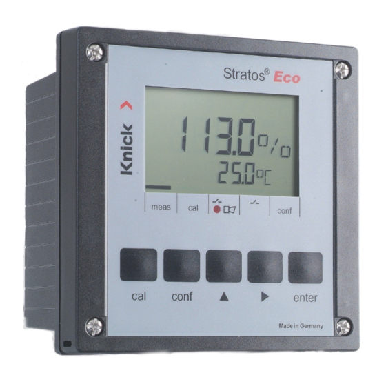
- Page 1 Stratos® Eco 2405 Oxy User Manual Latest Product Information: www.knick.de...
- Page 2 Please observe the applicable local or national regulations concerning the disposal of “waste electrical and electronic equipment”. Knick Elektronische Messgeräte GmbH & Co. KG Beuckestraße 22 14163 Berlin Germany Phone: +49 30 80191-0 Fax: +49 30 80191-200 Web: www.knick.de Email: info@knick.de...
-
Page 3: Table Of Contents
Table of Contents Safety Information ................. 5 Intended Use ....................7 Registered Trademarks .................7 Quickstart Guides ...................8 Overview of Stratos Eco 2405 Oxy ..........9 Assembly ..................10 Package Contents ..................10 Mounting Plan ....................11 Pipe Mounting, Panel Mounting .............12 Installation and Connection ............14 Installation Instructions ................14... - Page 4 Table of Contents Limit Function ....................50 Controlling a Rinsing System ..............52 Connecting a Rinsing System ..............53 Parameters ..................54 Factory Settings of Parameters ...............54 Parameters – Individual Settings ............56 Calibration ..................58 Calibration to Percent Saturation (SAT), in Water ......60 Calibration to Concentration (Conc), in Air ........62 Zero Calibration ...................64 Product Calibration ..................66 Temp Probe Adjustment .............69...
-
Page 5: Safety Information
Safety Information Safety information – Be sure to read and observe the following instructions! The device has been manufactured using state of the art technology and it complies with applicable safety regulations. When operating the device, certain conditions may nevertheless lead to danger for the operator or damage to the device. -
Page 7: Intended Use
The device has been designed for application with amperometric sensors, e.g. Knick SE 703 / SE 706. It provides two current outputs (for transmission of measured value and temperature, for example), two contacts, and a universal power supply 24 ... 230 V AC/DC, AC: 45 ... -
Page 8: Quickstart Guides
Safety Instructions In official EU languages and others. • FM and Control Drawings • EC Declarations of Conformity Quickstart Guides More languages on our website: www.knick.de • Installation and Commissioning • Operation • Menu structure • Calibration • Error messages and recommended actions... -
Page 9: Overview Of Stratos Eco 2405 Oxy
Overview Overview of Stratos Eco 2405 Oxy Do not connect + Output 1 Output 1 terminal ! – Output 1/2 Cathode Output 2 Guard + Output 2 DO input Reference Relay 1 electrode Relay 1 Anode Not in use Temp... -
Page 10: Assembly
Assembly Package Contents Check the shipment for transport damage and completeness. The package should contain: • Front unit • Rear unit • Bag containing small parts • CD-ROM with documentation • Specific test report • Passcode sticker 1 Jumper (2 x) 6 Sealing insert (1 x) 2 Washer (1 x), for conduit mounting: 7 Rubber reducer (1 x) -
Page 11: Mounting Plan
Assembly Mounting Plan 1 Cable gland (3 x) 2 Knockouts for cable gland or 1/2“ conduit, ø 21.5 mm (2 knockouts) Conduits not included! 3 Knockout for pipe mounting (4 x) 4 Knockout for wall mounting (2 x) Fig.: Mounting plan (All dimensions in mm!) -
Page 12: Pipe Mounting, Panel Mounting
Assembly Pipe Mounting, Panel Mounting 1 ZU 0276 protective hood (if required) 2 Hose clamp with worm gear drive to DIN 3017 (2 x) 3 Pipe-mount plate (1 x) 4 For vertical or horizontal posts or pipes 5 Self-tapping screw (4 x) Fig.: ZU 0274 pipe-mount kit (All dimensions in mm!) Fig.: ZU 0276 protective hood for wall and pipe mounting (All dimensions in mm!) - Page 13 Assembly 1 Screw (4 x) max. 25 2 Gasket (1 x) 3 Control panel 4 Span piece (4 x) 5 Threaded sleeve (4 x) Panel cut-out 138 x 138 mm (DIN 43700) 1...22 Fig.: ZU 0275 panel-mount kit (All dimensions in mm!)
-
Page 14: Installation And Connection
20.5 to 253V AC/DC. • All parameters must be set by a system administrator prior to commissioning. The terminals are suitable for single wires and flexible leads up to 2.5 mm (AWG 14). Terminal Assignments Fig.: Stratos Eco 2405 Oxy terminal assignments... - Page 15 Installation and Connection 1 ESD shield covering the signal inputs (Screw off for assembly) Note: The cable shield must end under the ESD shield. (Cut lines if required.) 2 Terminals for temperature probe 3 Terminals for sensor 4 Power supply connection Fig.: Information on installation, rear side of device Division 2 Wiring The connections to the device must be installed...
-
Page 17: Wiring Example
Wiring Example Sensors with Connection via VP Cable Stratos Eco 2405 Oxy Please note: The polarization voltage is factory set to 675 mV. When using a sensor with a different polarization volt- age, you must change this setting before connecting... -
Page 18: Protective Wiring Of Relay Outputs
Protective Wiring of Relay Outputs Protective Wiring of Relay Contacts Relay contacts are subjected to electrical erosion. Especially with inductive and capacitive loads, the service life of the contacts will be reduced. For suppression of sparks and arcing, components such as RC combinations, nonlinear resistors, series resistors and diodes should be used. - Page 19 Protective Wiring of Relay Outputs Typical Protective Wiring Measures A: DC application with inductive load B: AC/DC applications with capacitive load C: Connection of incandescent lamps A1 Inductive load A2 Free-wheeling diode, e.g. 1N4007 (Observe polarity) A3 Contact B1 Capacitive load B2 Resistor, e.g.
-
Page 20: User Interface And Display
User Interface and Display User Interface 1 Display 3 Alarm LED 2 Mode indicators (no keys), 4 Keypad from left to right: - Measuring mode - Calibration mode - Alarm - Cleaning contact - Configuration mode... - Page 21 User Interface and Display Display 9 10 1 Passcode entry 14 Secondary display 2 Not in use 15 Manual temperature specification 3 Temperature 16 Hold mode active 4 Current output 17 Waiting time running 5 Limit values 18 Sensor data 6 Alarm 19 Main display 7 Sensocheck...
-
Page 22: Operation: Keypad
User Interface and Display Operation: Keypad Start, exit calibration Start, exit configuration • Select digit position (selected position blinks) • Menu navigation • Edit digit • Menu navigation • Calibration: Continue in program sequence • Configuration: Confirm entries, next configuration step •... -
Page 23: Safety Functions
Safety Functions Sensocheck, Sensoface Sensor Monitoring Sensocheck continuously monitors the sensor and its wiring. Sensocheck can be switched off (Configuration, page 48). Sensoface provides information on the sensor condition. The slope and response time during calibration are evaluated. The three Sensoface indicators provide the user with informa- tion on wear and required maintenance of the sensor. -
Page 24: Hold Mode
Safety Functions Hold Mode Display: The Hold mode is a safety state during configuration and calibration. Output current is frozen (Last) or set to a fixed value (Fix). Alarm and limit contacts are disabled. If the calibration or configuration mode is exited, the device remains in the Hold mode for safety reasons. - Page 25 Safety Functions Alarm Alarm delay is 10 seconds. During an error message the alarm LED blinks. Error messages can also be signaled by a 22 mA output current. The alarm contact is activated by alarm or power failure, see also page 49.
-
Page 26: Configuration
Configuration In the Configuration mode you set the device parameters. Activation conf Activate using conf Enter passcode “1200“ Edit parameter using and , confirm/proceed using enter. (Exit by pressing conf, then enter.) HOLD The output current is frozen (at its last value or at a preset fixed value, depend- ing on the configuration), limit and During configu-... -
Page 27: Menu Structure Of Configuration
Configuration Menu Structure of Configuration The configuration steps are assigned to different menu groups. Using the arrow keys, you can jump between the individual menu groups. Each menu group contains menu items for setting the parameters. Pressing enter opens a menu item. The values are edited using the arrow keys. -
Page 28: Overview Of Configuration Steps
Configuration Overview of Configuration Steps Code Menu Selection Output 1 Select sensor type Standard (Type A) / Sensors with higher current (Type B) Select saturation / concentration Select current range Enter current start Enter current end Time constant of output filter 22 mA signal in the case of error Signal behavior during HOLD Enter fixed value... - Page 29 Configuration Code Menu Selection Calibration mode Select saturation / concentration Enter cal timer interval Alarm settings Select Sensocheck Relay 1: Limit Select contact function Select contact response Enter setpoint Enter hysteresis Enter delay Rinsing probes Rinse interval Rinse duration Contact response...
-
Page 30: Output 1
Detection limit in air (25 °C) 40 ... 110 nA 0.03 ppm 50 ... 110 nA 0.006 ppm B (sensors with higher 290 ... 500 nA current) Note: Stratos Eco 2405 Oxy has as device a resolution of 0.01 ppm. - Page 31 Configuration Code Display Action Choices Select sensor type A / B Type A (see table on left-hand side) (SE 703/ Select using. SE 706) Press enter to proceed. Type B (sensors with higher current) Select process variable (valid for all following settings): mg/l •...
- Page 32 Configuration Output 1 Output current range, current start, current end 1 Press conf key. conf 2 Enter passcode 1200. 3 Output 1 menu group is displayed. All items of this menu group are indicated by the “o1. ” code. 4 Press enter to select menu, edit using arrow keys (see page 33).
- Page 33 Configuration Code Display Action Choices Set output current range 4-20 mA Select usingkey, (0 - 20 mA) press enter to proceed. 000.0 % Current start Enter lower end of scale. (mg/l, Select usingkey, ppm) edit number using key. Press enter to proceed. Current end 200.0 % Enter upper end of scale,...
- Page 34 Configuration Output 1 Time constant of output filter 1 Press conf key. conf 2 Enter passcode 1200. 3 Output 1 menu group is displayed. All items of this menu group are indicated by the “o1. ” code. 4 Press enter to select menu, edit using arrow keys (see page 35).
- Page 35 Configuration Code Display Action Choices Time constant of output filter 0 sec 0 ... 120 sec Default setting: 0 s (inactive). To specify a time constant: Select usingkey, edit number using key. Press enter to proceed. Time Constant of Output Filter (Attenuation) To smoothen the current output, a low-pass filter with adjustable filter time constant can be switched on.
- Page 36 Configuration Output 1 Output current during Error and HOLD 1 Press conf key. conf 2 Enter passcode 1200. 3 Output 1 menu group is displayed. All items of this menu group are indicated by the “o1. ” code. 4 Press enter to select menu, edit using arrow keys (see page 37).
- Page 37 Configuration Code Display Action Choices 22 mA signal for error message (OFF / ON) Select usingkey, press enter to proceed. LAST Output signal during HOLD LAST: During HOLD the last (LAST / FIX) measured value is main- tained at the output FIX: During HOLD a value (to be entered) is maintained at the output...
-
Page 38: Output 2
Configuration Output 2 Temperature unit and probe, output current 1 Press conf key. conf 2 Enter passcode 1200. 3 Select Output 2 menu group using arrow keys. All items of this menu group are indi- cated by the “o2. ” code. 4 Press enter to select menu, edit using arrow keys (see page 39). - Page 39 Configuration Code Display Action Choices Specify temperature unit °C Select usingkey, (°C / °F) press enter to proceed. 22NTC Select temperature probe Select usingkey, (30NTC) press enter to proceed. 4 - 20 mA Select output current range Select usingkey, (4 - 20 mA/ press enter to proceed.
- Page 40 Configuration Output 2 Time constant of output filter 1 Press conf key. conf 2 Enter passcode 1200. 3 Select Output 2 menu group using arrow keys. All items of this menu group are indi- cated by the “o2. ” code. 4 Press enter to select menu, edit using arrow keys (see page 41).
- Page 41 Configuration Code Display Action Choices Time constant of output filter 0 sec Default setting: (0 ... 120 sec) 0 sec (inactive). To specify a time constant: Select using key, edit number using key. Press enter to proceed. Time Constant of Output Filter To smoothen the current output, a low-pass filter with adjustable filter time constant can be switched on.
- Page 42 Configuration Output 2 Temperature error, output current during HOLD 1 Press conf key. conf 2 Enter passcode 1200. 3 Select Output 2 menu group using arrow keys. All items of this menu group are indi- cated by the “o2. ” code. 4 Press enter to select menu, edit using arrow keys (see page 43).
- Page 43 Configuration Code Display Action Choices 22 mA signal for error message Select usingkey, press enter to proceed. Output signal during HOLD LAST: During HOLD the last measured value is main- tained at the output FIX: During HOLD a value (to be entered) is maintained at the output Select usingkey,...
-
Page 44: Correction
Configuration Correction Polarization voltage / Membrane temperature compensation / Process pressure / Salinity correction 1 Press conf key. conf 2 Enter passcode 1200. 3 Select Correction menu group using arrow keys. All items of this menu group are indi- cated by the “Co. ” code. 4 Press enter to select menu, edit using arrow keys (see page 45). - Page 45 Configuration Code Display Action Choices Enter polarization voltage Select usingkey, edit number usingkey. Press enter to proceed. Membrane temperature 01.00 compensation Select position using key and edit number using key. Press enter to proceed. Select pressure unit Select usingkey, press enter to proceed. Process pressure correction Enter process pressure.
-
Page 46: Calibration Mode
Configuration Calibration Mode 1 Press conf key. conf 2 Enter passcode 1200. 3 Select Calibration mode menu group using arrow keys. All items of this menu group are indicated by the “CA. ” code. 4 Press enter to select menu, edit using arrow keys (see page 47). - Page 47 Configuration Code Display Action Choices Specify calibration mode (calibration to saturation or concentration) Select usingkey, press enter to proceed. Cal timer interval The cal timer reminds you to calibrate in time. Select using, edit number using key. Press enter to proceed. Please note: When calibrating in air-saturated water (standard practice for biotech- nological processes), you should select calibration to saturation (SAT).
-
Page 48: Alarm Settings
Configuration Alarm Settings 1 Press conf key. conf 2 Enter passcode 1200. 3 Select Alarm settings menu group using arrow keys. All items of this menu group are indicated by the “AL. ” code. 4 Press enter to select menu, edit using arrow keys (see page 49). - Page 49 Configuration Code Display Action Choices Select Sensocheck (continuous monitoring of sensor) Select usingkey, press enter to proceed. Alarm Contact Alarm The alarm contact is closed during normal operation (N/C). It opens in the case of alarm or power outage. As a result, a failure message is provided even in the case of line breakage (fail-safe behavior).
-
Page 50: Limit Function
Configuration Limit Function Relay 1 Press conf key. conf 2 Enter passcode 1200. 3 Select Limit function menu group using arrow keys. All items of this menu group are indicated by the “L1. ” code. 4 Press enter to select menu, edit using arrow keys (see page 51). - Page 51 Configuration Code Display Action Choices Contact function (see below for function principle) Select usingkey, press enter to proceed. Contact response N/C: normally closed contact N/O: normally open contact Select usingkey, press enter to proceed. 000.0 % Setpoint Select usingkey, (xxx.x %) edit number using key.
-
Page 52: Controlling A Rinsing System
Configuration Controlling a Rinsing System conf “Clean” contact 1 Press conf key. 2 Enter passcode 1200. 3 Select Rinsing probes menu group using arrow keys. All items of this menu group are indicated by the “Pb. ” code. 4 Press enter to select menu, edit using arrow keys (see next page). -
Page 53: Connecting A Rinsing System
Configuration Code Display Action Choices Rinsing interval 0.000 h Select using key, enter (x.xxx h) number using , press enter to proceed. 0060 s Rinse duration Select using key, (xxxx s) enter number using , press enter to proceed. Contact response N/C: normally closed contact (N/O) -
Page 54: Parameters
Parameters Factory Settings of Parameters Activation: Simultaneously press conf + right arrow key and enter passcode “4321“. The lower display line reads “Clear“. To prevent accidental resetting, “NO“ is set as default (blinking in the main display). Press one of the arrow keys to select “YES“... - Page 55 Parameters Code Parameter Factory setting Polarization voltage Membrane temp. compensation Pressure unit Pressure Salinity Calibration mode Cal interval Sensocheck Contact function Contact response Setpoint Hysteresis Delay Rinsing interval Rinse duration Contact type Please note: Fill in your configuration data on the following pages. Please note: Factory settings for the calibration data are 60.0 nA (slope) and 0.000 nA (zero).
-
Page 56: Parameters - Individual Settings
Parameters Parameters – Individual Settings Code Parameter Setting Sensor type %, mg/l, ppm 0/4-20 mA Current start Current end Filter time 22mA signal HOLD response Fix current Unit °C / °F Temp probe 0/4 ... 20mA Current start Current end Filter time 22mA signal HOLD response... - Page 57 Parameters Code Parameter Setting Fix current Polarization voltage Membrane temp. compensation Pressure unit Pressure Salinity Calibration mode Cal interval Sensocheck Contact function Contact response Setpoint Hysteresis Delay Rinsing interval Rinse duration Contact type...
-
Page 58: Calibration
Calibration Calibration adjusts the device to the sensor. Activation Activate by pressing cal Enter passcode: • Zero point 1001 • Water/Air 1100 Edit parameter using and. Confirm and proceed by pressing enter. (Exit by pressing cal, then enter.) HOLD During calibration the device remains in the Hold mode for reasons of safety. - Page 59 Calibration Information on Calibration It is always recommended to calibrate in air. Compared to water, air is a calibration medium which is easy to handle, stable, and thus safe. In the most cases, however, the sensor must be dismounted for a calibration in air. When dealing with bio- technological processes which require sterile conditions, the sensor cannot be removed for calibration.
-
Page 60: Calibration To Percent Saturation (Sat), In Water
Calibration Calibration to Percent Saturation (SAT), in Water Display Action Remark Press cal key, enter code 1100. SAT or Conc calibra- Select using key, tion is selected during edit number using key. configuration. Press enter to proceed. Device switches to Hold mode. - Page 61 Calibration Display Action Remark Enter setpoint value for Default: last value saturation entered Select using key, edit number using key. Press enter to proceed. Display of new calibration values New calibration: Press cal key. (related to 25°C at 1013 mbars). Ther zero point remains unchanged, for zero calibration see page 67.
-
Page 62: Calibration To Concentration (Conc), In Air
Calibration Calibration to Concentration (Conc), in Air Display Action Remark Press cal key, enter code 1100. SAT or Conc calibra- Presskey to select position, tion is selected during enter number usingkey. configuration. Press enter to proceed. Device switches to Hold mode. If an invalid code is entered, the device returns to measuring... - Page 63 Calibration Display Action Remark Enter default for concentration Default value is calcu- Presskey to select position, lated from rel. humid- enter number usingkey. ity, cal pressure, and Press enter to proceed. cal temperature (the unit of measurement, ppm or mg/l, is preset during configuration).
-
Page 64: Zero Calibration
Calibration Zero Calibration The sensor models SE 703 and SE 706 have a low zero current. Therefore, you should not perform a zero calibration with Stratos Eco 2405. If you still wish to perform a zero calibration, the sensor should remain for at least 10 to 30 minutes in an oxygen-free calibration medium in order to obtain stable, non-drifting values. - Page 65 Calibration Display Action Remark Select calibration (press cal key). Device is in the Hold mode. If an invalid code is entered, the Enter passcode 1001. device returns to Select using key, measuring mode. edit number using key. Press enter to proceed. Place sensor in oxygen-free medium.
-
Page 66: Product Calibration
Calibration Product Calibration Calibration by comparison During product calibration the sensor remains in the process. The measurement is only interrupted briefly. Procedure: The currently measured value is stored in the device for comparison. The comparison value is measured on the site, e.g. using a portable DO meter in a bypass. - Page 67 Calibration Display Action Remark Save currently measured value. Perform reference Press enter to proceed. measurement. Enter the reference value. Calculation of new Confirm by pressing enter. slope Display of new slope or new New calibration: Press cal. zero (related to 25 °C and 1013 mbars).
-
Page 69: Temp Probe Adjustment
Temp Probe Adjustment Display Action Remark Select calibration Wrong settings Press cal key, enter code 1015. change the measure- Presskey to select position, ment properties! If enter number usingkey, an invalid code is confirm by pressing enter. entered, the device returns to measuring mode. -
Page 70: Diagnostics Functions
Diagnostics Functions Display Action Display of output currents Press enter while in measuring mode. The current at output 1 is shown in the main display, the current at output 2 in the secondary display. After 5 sec the device returns to measuring mode. Display of calibration data (Cal Info) Press cal while in measuring mode and enter code 0000. - Page 71 Diagnostics Functions These functions are used for testing the connected peripherals. Display Action Specify current for output 1 Press conf while in measuring mode and enter code 5555. The main display indicates the current provided by output 1. This value can be edited. To do so, select the position usingkey, edit number using key.
-
Page 72: Error Messages (Error Codes)
Error Messages (Error Codes) Problem Error Display Possible causes ERR 01 SAT range Measured value • Sensor defective blinks • Wrong sensor connected • Measurement range exceeded ERR 02 Conc range Measured value • Sensor defective blinks • Wrong sensor connected •... - Page 73 Error Messages (Error Codes) Icon Problem Error (blinks) Possible causes ERR 03 Temperature probe Open or short circuit Temperature range exceeded ERR 11 Current output 1 Current below 0 (3.8) mA ERR 12 Current output 1 Current above 20.5 mA ERR 13 Current output 1 Current span too small / too large...
-
Page 74: Calibration Error Messages
Calibration Error Messages Problem Icon blinks: Possible causes Slope out of range Wrong calibration values specified (relative humidity, pressure, saturation, concentration) Calibration aborted after 12 minutes Sensor defective or dirty • No electrolyte in the sensor • Sensor cable insufficiently shielded or defective •... -
Page 75: Operating States
Operating States Operating status Measure Cal Info 20 s (cal) 0000 Error Info 20 s (conf ) 0000 Calibration (cal) 1100 Temp adjustment (cal) 1015 Product calibration (cal) 1105 Configuration 20 min (conf ) 1200 Sensor monitor 20 min (conf ) 2222 Current source 1 20 min (conf ) 5555... -
Page 77: Sensoface
Sensoface (Sensocheck must have been activated during configuration.) The smiley in the display (Sensoface) alerts to sensor problems (defective cable, maintenance request). The permitted calibration ranges and the conditions for a friendly, neutral or sad Sensoface are summarized in the following chart. Additional icons refer to the error cause. - Page 79 Sensoface Type B Sensors (Sensors with Higher Current) Response Slope Zero point Cal timer time Permitted 200 ... 550 nA -2 ... +2 nA max. 720 s range > 250 ... < 500 nA > -0.5 ... < 0.5 nA <...
-
Page 81: Appendix
Appendix Product Line and Accessories Devices Order No. Stratos Eco 2405 Oxy 2405 Oxy Mounting Accessories Pipe-mount kit ZU 0274 Panel-mount kit ZU 0275 Protective hood ZU 0276 For more information concerning our sensors and fittings product line, please refer to our website:... -
Page 82: Specifications
Specifications DO input Measuring current –2 ... +1800 nA Resolution 0.05 nA (with V ≤ 800 mV and ≤ 200 mV) Saturation 0... 200% (-10 ... 80 °C) 1,2,3) Meas. error 0.5 % meas.val. + 0.5 % Concentration 0,00 ... 20.00 mg/l (-10 ... - Page 83 Specifications Sensor monitoring Sensocheck Monitoring for short circuits / open circuits (can be disabled) Sensoface Provides information on the sensor condition (evaluation of zero/slope, response time, calibration interval, Sensocheck) Temperature input NTC 22 kΩ / NTC 30 kΩ 2-wire connection, adjustable Measuring range –20.0 ...
- Page 84 Specifications Alarm contact Relay contact, floating Contact ratings AC< 250 V / < 3 A / < 750 VA DC< 30 V / < 3 A / < 90 W Contact response N/C (fail-safe type) Response delay 10 s Limit value Output via relay contact Contact ratings AC<...
- Page 85 Specifications Service functions Current source Current specifiable for output 1 and 2 (00.00 ... 22.00 mA) Device self-test Automatic memory test (RAM, FLASH, EEPROM) Display test Display of all segments Last Error Display of last error occurred Sensor monitor Display of direct, uncorrected sensor signal Data retention Parameters and calibration data >...
- Page 86 Specifications Enclosure Molded enclosure made of PBT, glass bead reinforced Color Black Mounting • Wall mounting • Pipe mounting: Ø 40 ... 60 mm 30 ... 45 mm • Panel mounting, cutout to DIN 43 700, sealed against panel Dimensions H 144 mm, W 144 mm, D 105 mm Ingress protection IP 65 / NEMA 4X...
-
Page 87: Approvals - Canada
Approvals – Canada Warnings and Notes to Ensure Safe Operation WARNING! Do not disconnect equipment unless power has been switched off. CAUTION! Clean only with antistatic moistened cloth. CAUTION! Substitution of components may impair suitability for hazardous locations. • The equipment shall be installed and protected from mechanical impact and ultraviolet (UV) sources. - Page 88 Approvals – Canada CAUTION! Use supply wires suitable for 30 °C above ambient and rated at least 250 V. CAUTION! Use signal wires suitable for at least 250V. OBSERVE THE SPECIFICATIONS OF THE CONTROL DRAWING!
-
Page 89: Index
Index 22 mA signal for error message 37, 43 Accessories 81 Alarm contact 49 Alarm setings 25, 48 Approvals 87 Assembly 10 Calibration 58 Calibration mode selection 46 Calibration to concentration (Conc) 62 Calibration to percent saturation (SAT) 60 Cal timer interval 46 Error messages 74 Product calibration 66 Zero calibration 64... - Page 90 Index Temperature 38 Temperature error 42 Time constant of output filter 40 Configuration: Rinsing probes 52 Connection 14 CSA warnings and notes 87 Current start / end 33, 39 Device self-test 23 Diagnostics functions 70 Display of calibration data 70 Display of last error message 70 Display of output currents 70 Display of sensor current 70...
- Page 91 Index Installation 14 Intended use 7 Keypad 22 Measurement 69 Mounting plan 11 Operating states 75 Output filter 34, 40 Overview 9 Overview of configuration steps 28 Package contents 10 Panel mounting 13 Panel-mount kit 13 Parameters Factory settings 54 Individual settings 56 Passcodes 93 Pipe mounting 12...
- Page 92 Index Relay 50, 52 Relay contacts 18 Rinse contact 52 Rinsing interval 53 Rinsing probes 52 Rinsing system 53 Safety information 5, 87 Salinity correction 45 Self-test 23 Sensocheck 23, 48, 79 Configuration 49 Sensoface 23, 77, 79 Sensor connection 17 Sensor monitor 70 Short instructions 8 Specifications 82...
-
Page 93: Passcodes
Passcodes Calibration Key + passcode Menu item Page CAL info (display of zero,slope) Zero calibration Calibration (water / air) Product calibration Temp probe adjustment Configuration Key + passcode Menu item Page Error info (display of last error, erase) Configuration Sensor monitor (sensor current) Current source 1 (specify output current) - Page 94 Knick Elektronische Messgeräte GmbH & Co. KG Headquarters Beuckestraße 22 • 14163 Berlin Germany Phone: +49 30 80191-0 Fax: +49 30 80191-200 info@knick.de www.knick.de Local Contacts www.knick-international.com Copyright 2020 • Subject to change This document was last updated on April 6, 2020 The latest documents are available for download on our website under the corresponding product description.
Need help?
Do you have a question about the Stratos Eco 2405 Oxy and is the answer not in the manual?
Questions and answers