Table of Contents
Advertisement
Quick Links
Advertisement
Table of Contents

Related Manuals for Knick Stratos Eco 2405 Cond


Summary of Contents for Knick Stratos Eco 2405 Cond
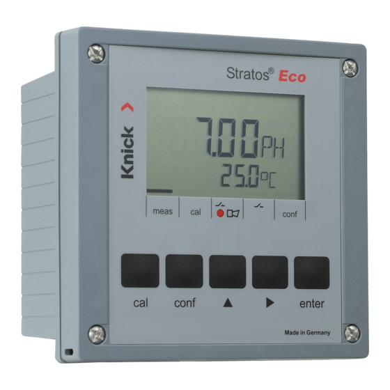
- Page 1 Stratos® Eco 2405 Cond User Manual...
- Page 2 Disposal Please observe the applicable local or national regulations concerning the disposal of “waste electrical and electronic equipment”. Knick Elektronische Messgeräte GmbH & Co. KG Beuckestraße 22 14163 Berlin Germany...
-
Page 3: Table Of Contents
Table of Contents Safety Information ................. 5 Intended Use ....................7 Registered Trademarks .................7 Quickstart Guides ...................8 Overview of Stratos Eco 2405 Cond ........... 9 Assembly ..................10 Package Contents ..................10 Mounting Plan ....................11 Pipe Mounting, Panel Mounting .............12 Installation and Connection ............14 Installation Instructions ................14... - Page 4 Table of Contents Limit Function ....................56 Controlling a Rinsing Probe ..............58 Connecting a Rinsing System ..............59 Parameters ..................60 Factory Settings of Parameters ...............60 Parameters – Individual Settings ............62 Calibration ..................64 Calibration by Entry of Cell Constant ............66 Calibration with Calibration Solution ..........68 Product Calibration ..................70 Temp Probe Adjustment .............72 Measurement ................72...
-
Page 5: Safety Information
Safety Information Safety information – Be sure to read and observe the following instructions! The device has been manufactured using state of the art technology and it complies with applicable safety regulations. When operating the device, certain conditions may nevertheless lead to danger for the operator or damage to the device. -
Page 7: Intended Use
Intended Use Stratos Eco 2405 Cond is used for measurement of electrical conductivity and temperature in liquids. Fields of application are: biotechnology, chemical industry, environment, food processing, water/waste-water treatment. The sturdy molded enclosure can be fixed into a control panel or mounted on a wall or at a post. -
Page 8: Quickstart Guides
Safety Instructions In official EU languages and others. • FM and Control Drawings • EC Declarations of Conformity Quickstart Guides More languages on our website: www.knick.de • Installation and Commissioning • Operation • Menu structure • Calibration • Error messages and recommended actions... -
Page 9: Overview Of Stratos Eco 2405 Cond
Overview Overview of Stratos Eco 2405 Cond 2/4 El cond + Output 1 Output 1 cond I hi input – Output 1/2 cond U hi + Output 2 cond U lo Output 2 cond I lo SG (solution Relay ground) -
Page 10: Assembly
Assembly Package Contents Check the shipment for transport damage and completeness. The package should contain: • Front unit • Rear unit • Bag containing small parts • CD-ROM with documentation • Specific test report • Passcode sticker 1 Jumper (2 x) 6 Sealing insert (1 x) 2 Washer (1 x), for conduit mounting: 7 Rubber reducer (1 x) -
Page 11: Mounting Plan
Assembly Mounting Plan 1 Cable gland (3 x) 2 Knockouts for cable gland or 1/2“ conduit, ø 21.5 mm (2 knockouts) Conduits not included! 3 Breakout for pipe mounting (4 x) 4 Breakout for wall mounting (2 x) Fig.: Mounting plan (All dimensions in mm!) -
Page 12: Pipe Mounting, Panel Mounting
Assembly Pipe Mounting, Panel Mounting 1 ZU 0276 protective hood (if required) 2 Hose clamp with worm gear drive to DIN 3017 (2 x) 3 Pipe-mount plate (1 x) 4 For vertical or horizontal posts or pipes 5 Self-tapping screw (4 x) Fig.: ZU 0274 pipe-mount kit (All dimensions in mm!) Fig.: ZU 0276 protective hood for wall and pipe mounting (All dimensions in mm!) - Page 13 Assembly 1 Screw (4 x) max. 25 2 Gasket (1 x) 3 Control panel 4 Span piece (4 x) 5 Threaded sleeve (4 x) Panel cut-out 138 x 138 mm (DIN 43700) 1...22 Fig.: ZU 0275 panel-mount kit (All dimensions in mm!)
-
Page 14: Installation And Connection
20.5 ... 253 V AC/DC. • All parameters must be set by a system administrator prior to commissioning. The terminals are suitable for single wires and flexible leads up to 2.5 mm (AWG 14). Terminal Assignments Fig.: Stratos Eco 2405 Cond terminal assignments... - Page 15 Installation and Connection 1 Terminals for temperature probe and outer shield 2 Terminals for sensor 3 Terminals for power supply Fig.: Information on installation, rear side of device Division 2 Wiring The connections to the device must be installed in accordance with the National Electric Code (ANSI NFPA 70) Division 2 hazardous (classified) location non-incendive wiring techniques.
-
Page 16: Wiring Examples
Any 4-electrode sensors with cell constants from 0.0050 cm to 19.9999 cm , with or without temperature detector, can be connected, e.g. SE600, SE603. Stratos Eco 2405 Cond CAUTION! Place jumper across terminals 4 and 5! When using a sensor with Solution Ground connection (SG) or... - Page 17 Cond measurement with 2-electrode sensor (coaxial electrodes) Any 2-electrode sensors with cell constants from 0.0050 cm to 19.9999 cm , with or without temperature detector, can be connected, e.g. SE610. Stratos Eco 2405 Cond Jumper Jumper CAUTION! Place jumpers: • across terminals 1 and 2 •...
- Page 18 Cond measurement with SE604 2-electrode sensor (coaxial electrodes) Connection using cable ZU 0645 (3 m), ZU 0569 (5 m), ZU 0570 (10 m) ZU 0589 (15 m), ZU 0590 (20 m), or ZU 0660 (30 m) Stratos Eco 2405 Cond Female connector Sensor cap...
- Page 19 Wiring Examples Cond measurement with SE630 2-electrode sensor (formerly ZU 0071) Connection using included GDM connector with 5-m cable Stratos Eco 2405 Cond GDM connector...
-
Page 20: Sensor Connection Using Vp Cables
Wiring Examples Sensor Connection Using VP Cables Connection diagrams for connecting conductivity sensors using VP cables (e.g. SE620) are provided on request. Any 2- or 4-electrode sensors with cell constants from 0.0050 cm 19.9999 cm , with or without temperature detector, can be connected. -
Page 22: Protective Wiring Of Relay Outputs
Protective Wiring of Relay Outputs Protective Wiring of Relay Contacts Relay contacts are subjected to electrical erosion. Especially with inductive and capacitive loads, the service life of the contacts will be reduced. For suppression of sparks and arcing, components such as RC combinations, nonlinear resistors, series resistors and diodes should be used. - Page 23 Protective Wiring of Relay Outputs Typical Protective Wiring Measures A: DC application with inductive load B: AC/DC applications with capacitive load C: Connection of incandescent lamps A1 Inductive load A2 Free-wheeling diode, e.g. 1N4007 (Observe polarity) A3 Contact B1 Capacitive load B2 Resistor, e.g.
-
Page 24: User Interface And Display
User Interface and Display User Interface 1 Display 3 Alarm LED 2 Mode indicators (no keys), 4 Keypad from left to right: - Measuring mode - Calibration mode - Alarm - Wash contact - Configuration mode... - Page 25 User Interface and Display Display 9 10 1 Passcode entry 14 Secondary display 2 Not in use 15 Manual temp specification 3 Temperature 16 Hold mode active 4 Current output 17 Waiting time running 5 Limit values 18 Sensor data 6 Alarm 19 Main display 7 Sensocheck...
-
Page 26: Operation: Keypad
User Interface and Display Operation: Keypad Start, end calibration conf Start, end configuration • Select digit position (selected position blinks) • Menu navigation • Edit digit • Menu navigation enter • Calibration: Continue in program sequence • Configuration: Confirm entries, next configuration step •... -
Page 27: Safety Functions
Safety Functions Sensocheck, Sensoface Sensor Monitoring Sensocheck continuously monitors the sensor and its wiring. Sensocheck can be switched off (Configuration, Pg 54). Sensoface provides information on the conductivity sensor condition. Significant sensor polarization effects or an excessive cable capacitance are indicated. GainCheck Device Self-Test A display test is carried out, the software version is displayed, and the memory and measured-value transfer are checked. -
Page 28: Hold Mode
Safety Functions Hold Mode Display: The Hold mode is a safety state during configuration and calibration. Output current is frozen (Last) or set to a fixed value (Fix). Alarm and limit contacts are disabled. If the calibration or configuration mode is exited, the device remains in the Hold mode for safety reasons. - Page 29 Safety Functions Alarm Alarm delay is 10 seconds. During an error message the alarm LED blinks. Error messages can also be signaled by a 22 mA output current. The alarm contact is activated by alarm or power failure, see also Pg 55.
-
Page 30: Configuration
Configuration In the Configuration mode you set the device parameters. Activation conf Activate by pressing conf Enter passcode “1200“ Edit parameter using and , confirm/proceed using enter. (End by pressing conf, then enter.) HOLD The output current is frozen (at its last value or at a preset fixed value, depend- ing on the configuration), limit and During configu-... -
Page 31: Menu Structure Of Configuration
Configuration Menu Structure of Configuration The configuration steps are assigned to different menu groups. Using the arrow keys, you can jump between the individual menu groups. Each menu group contains menu items for setting the parameters. Pressing enter opens a menu item. The values are edited using the arrow keys. -
Page 32: Overview Of Configuration Steps
Configuration Overview of Configuration Steps Code Menu Selection / Default out1 Output 1 o1.CELL Select sensor 2-electrode, 4-electrode o1.UnIT Select process variable μS, mS/cm, MΩ·cm, SAL, Conc NaCl HCl NaOH H o1.CoNC Select solution (Conc), see Pg Codes: o1.rNG Select current range 0-20 mA / 4-20 mA o1. - Page 33 Configuration Code Menu Selection / Default ALrt Alarm settings AL.SnSO Select Sensocheck ON / OFF rLAY Relay 1: Limit value L1.FCT Select contact function Lo / Hi L1.tYP Select contact response N/O / N/C L1.LEVL Enter setpoint xxxx L1.HYS Enter hysteresis xxxx L1.dLY Enter delay...
-
Page 34: Output 1
Configuration Output 1 Selecting the sensor type 1 Press conf key. conf 2 Enter passcode 1200. 3 Output 1 menu group is displayed. All items of this menu group are indicated by the “o1. ” code. 4 Press enter to select menu, edit using arrow keys (see Pg 35). - Page 35 Configuration Code Display Action Selection Select evaluation method: 2-El 2-electrode sensor / (2-El / 4-El) 4-electrode sensor Select usingkey, press enter to proceed. Note: Characters represented in gray are blinking and can be edited.
- Page 36 Configuration Output 1 Selecting the process variable 1 Press conf key. conf 2 Enter passcode 1200. 3 Output 1 menu group is displayed. All items of this menu group are indicated by the “o1. ” code. 4 Press enter to select menu, edit using arrow keys (see Pg 37).
- Page 37 Configuration Code Display Action Choices Select process variable: 000.0 mS (0.000 µS Select usingkey, 00.00 μS press enter to proceed. 000.0 μS 0000 μS 0.000 mS 00.00 mS Conductivity: 000.0 mS 0.000 ... 9.999 μS/cm 0.000 S/m 00.00 ... 99.99 μS/cm 00.00 S/m 000.0 ...
- Page 38 Configuration Output 1 Concentration measurement: Select process solutions 1 Press conf key. conf 2 Enter passcode 1200. 3 Output 1 menu group is displayed. All items of this menu group are indicated by the “o1. ” code. 4 Press enter to select menu, edit using arrow keys (see Pg 39).
- Page 39 Configuration Code Display Action Choices Only with 00.00 % Conc -01-SOL can you select the process (-01-SOL solution. -02-SOL Select using arrow key -03-SOL -04-SOL -01- NaCl -05-SOL) (0.00 ... 9.99 % by wt) (0 ... 120 °C) -02- HCl (0.00 ...
- Page 40 Configuration Output 1 Output current range, current start, current end 1 Press conf key. conf 2 Enter passcode 1200. 3 Output 1 menu group is displayed. All items of this menu group are indicated by the “o1. ” code. 4 Press enter to select menu, edit using arrow keys (see Pg 41).
- Page 41 Configuration Code Display Action Choices Set output current range 4-20 mA Select usingkey, (0 - 20 mA/ press enter to proceed. 4 - 20 mA) 000.0 mS Current start Enter lower end of scale. (xxx.x mS) Select usingkey, edit number using key, press enter to proceed.
- Page 42 Configuration Output 1 Time constant of output filter 1 Press conf key. conf 2 Enter passcode 1200. 3 Output 1 menu group is displayed. All items of this menu group are indicated by the “o1. ” code. 4 Press enter to select menu, edit using arrow keys (see Pg 43).
- Page 43 Configuration Code Display Action Choices Time constant of output filter 0 sec 0 ... 120 sec Default setting: 0 s (inactive). To specify a time constant: Select usingkey, edit number using key, press enter to proceed. Time Constant of Output Filter (Attenuation) To smoothen the current output, a low-pass filter with adjustable filter time constant can be switched on.
- Page 44 Configuration Output 1 Output current during Error and HOLD 1 Press conf key. conf 2 Enter passcode 1200. 3 Output 1 menu group is displayed. All items of this menu group are indicated by the “o1. ” code. 4 Press enter to select menu, edit using arrow keys (see Pg 45).
- Page 45 Configuration Code Display Action Choices 22 mA signal for error message (OFF / ON) Select usingkey, press enter to proceed. LAST Output signal during HOLD LAST: During HOLD the last (LAST / FIX) measured value is main- tained at the output FIX: During HOLD a value (to be entered) is maintained at the output...
-
Page 46: Output 2
Configuration Output 2 Temperature unit and probe, output current 1 Press conf key. conf 2 Enter passcode 1200. 3 Select Output 2 menu group using arrow keys. All items of this menu group are indicated by the “o2. ” code. 4 Press enter to select menu, edit using arrow keys (see Pg 47). - Page 47 Configuration Code Display Action Choices Specify temperature unit °C Select usingkey, (°C / °F) press enter to proceed. Pt100 Select temperature probe Select usingkey, (Pt1000, press enter to proceed. NTC30 kΩ, NTC8.55 kΩ) 4 - 20 mA Select output current range Select usingkey, (4 - 20 mA/ press enter to proceed.
- Page 48 Configuration Output 2 Time constant of output filter 1 Press conf key. conf 2 Enter passcode 1200. 3 Select Output 2 menu group using arrow keys. All items of this menu group are indi- cated by the “o2. ” code. 4 Press enter to select menu, edit using arrow keys (see Pg 49).
- Page 49 Configuration Code Display Action Choices Time constant of output filter 0 sec Default setting: (0 ... 120 sec) 0 sec (inactive). To specify a time constant: Select using key, edit number using key, press enter to proceed. Time Constant of Output Filter To smoothen the current output, a low-pass filter with adjustable filter time constant can be switched on.
- Page 50 Configuration Output 2 Temperature error, output current during HOLD 1 Press conf key. conf 2 Enter passcode 1200. 3 Select Output 2 menu group using arrow keys. All items of this menu group are indi- cated by the “o2. ” code. 4 Press enter to select menu, edit using arrow keys (see Pg 51).
- Page 51 Configuration Code Display Action Choices 22 mA signal for error (OFF / ON) message Select usingkey, press enter to proceed. LAST Output signal during HOLD LAST: During HOLD the last (LAST / FIX) measured value is main- tained at the output FIX: During HOLD a value (to be entered) is maintained at the output...
-
Page 52: Temperature Compensation
Configuration Temperature Compensation Temp compensation selection 1 Press conf key. conf 2 Enter passcode 1200. 3 Select Temperature compensation menu group using arrow keys. All items of this menu group are indicated by the “tc. ” code. 4 Press enter to select menu, edit using arrow keys (see Pg 53). - Page 53 Configuration Code Display Action Choices Select temp compensation (OFF OFF: Temperature compen- sation switched off Select usingkey, nACL press enter to proceed. LIN: Linear temperature nH3) compensation with entry of temperature coefficient and reference temperature nLF: Temperature compen- sation for natural waters to EN 27888 NaCl (nACL): Temperature compensation for ultrapure...
-
Page 54: Alarm Settings
Configuration Alarm Settings 1 Press conf key. conf 2 Enter passcode 1200. 3 Select Alarm settings menu group using arrow keys. All items of this menu group are indicated by the “AL. ” code. 4 Press enter to select menu, edit using arrow keys (see Pg 55). - Page 55 Configuration Code Display Action Choices Select Sensocheck (continuous monitoring of (ON / OFF) sensor) Select usingkey, press enter to proceed. Alarm Contact Alarm The alarm contact is closed during normal operation (N/C). It opens in the case of alarm or power outage.
-
Page 56: Limit Function
Configuration Limit Function Relay 1 Press conf key. conf 2 Enter passcode 1200. 3 Select Limit function menu group using arrow keys. All items of this menu group are indicated by the “L1. ” code. 4 Press enter to select menu, edit using arrow keys (see Pg 57). - Page 57 Configuration Code Display Action Choices Contact function (see below for function (Lo/Hi) principle) Select usingkey, press enter to proceed. Contact response N/C: normally closed contact (N/O N/O: normally open contact N/C) Select usingkey, press enter to proceed. 000.0 mS Setpoint Select usingkey, (xxx.x mS) edit number using key,...
-
Page 58: Controlling A Rinsing Probe
Configuration Controlling a Rinsing Probe conf “Clean” contact 1 Press conf key. 1 Press conf key. 2 Enter passcode 1200. 2 Enter passcode 1200. 3 Select Limit function menu group using 3 Select Rinsing probes menu group using arrow keys. All items of this menu group are arrow keys. -
Page 59: Connecting A Rinsing System
Configuration Code Display Action Choices Rinsing interval 0000 h Select using key, enter (x.xxx h) number using press enter to proceed. 0060 sec Rinse duration Select using key, (xxxx sec) enter number using press enter to proceed. Contact response N/C: normally closed contact (N/O) -
Page 60: Parameters
Parameters Factory Settings of Parameters Activation: Simultaneously press conf + right arrow key and enter passcode “4321“. The lower display line reads “Clear“. To prevent accidental resetting, “NO“ is set as default (blinking in the main display). Press one of the arrow keys to select “YES“ and confirm by pressing enter. - Page 61 Parameters Code Parameters Factory setting Temp compensation tc. LIN Temp coefficient 02.00%/K AL.SnSO Sensocheck L1.FCT Contact function L1.tYP Contact response L1.LEVL Setpoint 000.0 mS L1.HYS Hysteresis 001.0 mS L1.dLY Delay 0010 sec Rinsing interval Rinse duration Contact type Please note: Fill in your configuration data on the following pages.
-
Page 62: Parameters - Individual Settings
Parameters Parameters – Individual Settings Code Parameter Setting o1.CELL Sensor o1.UnIT Process variable o1.CoNC Solution (Conc) o1. rNG 0/4-20 mA o1. 4mA Current start o1.20mA Current end o1.FtME Filter time o1.FAIL 22mA signal o1.HoLD HOLD response o1.FIX Fix current o2.UnIT Unit °C / °F o2.rTD Temp probe... - Page 63 Parameters Code Parameter Setting o2.FtME Filter time o2.FAIL 22mA signal o2.HoLD HOLD response o2.FIX Fix current Temp compensation tc. LIN Temp coefficient AL.SnSO Sensocheck L1.FCT Contact function L1.tYP Contact response L1.LEVL Setpoint L1.HYS Hysteresis L1.dLY Delay Rinsing interval Rinse duration Contact type...
-
Page 64: Calibration
Calibration Calibration adjusts the device to the sensor. Activation Activate by pressing cal Enter passcode: • Entry of cell constant 1100 • With calibration solution 0110 • Product calibration 1105 • Temp probe adjustment 1015 Select using key. Edit parameter using . Press enter to proceed. - Page 65 Calibration Information on Calibration Calibration adapts the device to the conductivity sensor. Calibration can be performed by: • Input of cell constant (e.g. for ultrapure-water sensors) • Determining the cell constant with a known calibration solution (conductivity standard) • Product calibration (calibration by comparison) •...
-
Page 66: Calibration By Entry Of Cell Constant
Calibration Calibration by Entry of Cell Constant Input of cell constant with simultaneous display of uncorrected conductivity value and temperature Display Action Remark Press cal key, enter code 1100. Device is in the Hold Select using key, mode. edit number using key, If an invalid code is press enter to proceed. - Page 67 Calibration Display Action Remark The device now displays the conductivity and temperature. The measured value is shown in After end of calibra- the main display alternately with tion, the outputs “Hold”, “enter” blinks. remain in Hold mode End calibration by pressing for approx.
-
Page 68: Calibration With Calibration Solution
Calibration Calibration with Calibration Solution Input of temperature-corrected value of calibration solution (calibration standard) with simultaneous display of cell constant Display Action Remark Press cal key, enter code 0110. Device is in the Hold Select using key, mode. If an invalid edit number using ... - Page 69 Calibration Display Action Remark The determined cell constant is displayed. Press enter to confirm. The device now displays the con- ductivity and temperature. Clean sensor and re-place it in After end of calibra- the process. The measured value tion, the outputs is shown in the main display remain in Hold mode alternately with “Hold”.
-
Page 70: Product Calibration
Calibration Product Calibration Calibration by comparison For product calibration the measured variable is used as configured: conductivity (µS/cm, mS/cm, S/m), resistivity (MΩ·cm). During product calibration the sensor remains in the process. The measurement is only interrupted briefly. Calibration is without TC correction. Procedure: The currently measured value is stored in the device for comparison. - Page 71 Calibration Display Action Remark Enter sample value. The new cell constant is calculated. The determined cell constant is New calibration: Press cal. displayed. Press enter to confirm. The new value is shown in the After end of calibra- main display alternately with tion, the outputs “Hold”, “enter”...
-
Page 72: Temp Probe Adjustment
Temp Probe Adjustment Display Action Remark Select calibration Wrong settings Press cal key, enter code 1015. change the measure- Presskey to select position, ment properties! If enter number usingkey, an invalid code is press enter to confirm. entered, the device returns to measuring mode. -
Page 73: Diagnostics Functions
Diagnostics Functions Display Action Display of output currents Press enter while in measuring mode. The current at output 1 is shown in the main display, the current at output 2 in the secondary display. After 5 sec the device returns to measuring mode. Display of calibration data (Cal Info) Press cal while in measuring mode and confirm code 0000. - Page 74 Diagnostics Functions These functions are used for testing the connected peripherals. Display Action Specify current at output 1 Press conf while in measuring mode, enter code 5555. The current indicated in the main display for output 1 can be edited. Select usingkey, edit number usingkey.
-
Page 75: Error Messages (Error Codes)
Error Messages (Error Codes) Problem Error Display Possible causes ERR 01 Sensor Measured value • Wrong cell constant blinks • Measuring range violation • SAL > 45 ‰ • Sensor connection or cable defective ERR 02 Unsuitable sensor Measured value Conductance range >... - Page 76 Error Messages (Error Codes) Icon Problem Error (blinks) Possible causes ERR 03 Temperature probe Open or short circuit Temperature range exceeded ERR 11 Current output 1 Current below 0 (3.8) mA ERR 12 Current output 1 Current above 20.5 mA ERR 13 Current output 1 Current span too small / too large...
-
Page 77: Operating States
Operating States Operating status Measure Cal Info 20 s (cal) 0000 Error Info 20 s (conf ) 0000 Calibration (cal) 1100 Temp adjustment (cal) 1015 Product calibration (cal) 1105 Configuration 20 min (conf ) 1200 Sensor monitor 20 min (conf ) 2222 Current source 1 20 min (conf ) 5555... -
Page 78: Sensoface
Sensoface The smiley in the display (Sensoface) provides information about the sensor condition (defects, maintenance required, cable capacitance too high). It alerts to significant sensor polarization or excessive cable capacitance e.g. caused by an unsuitable cable or a cable that is too long. - Page 79 Sensoface Display Problem Status Sensor defect Wrong or defective sensor Significant polarization of sensor Excessive cable capacitance (see also Err 33, Error Messages on Pg 76). Temperature Temperature outside range for error TC, conc, SAL Please note: When very fast response times (t ) are required, e.g.
-
Page 81: Appendix
Appendix Product Line and Accessories Devices Order No. Stratos Eco 2405 Cond 2405 Cond Mounting Accessories Pipe-mount kit ZU 0274 Panel-mount kit ZU 0275 Protective hood ZU 0276 For more information concerning our sensors and fittings product line, please refer to our website:... -
Page 82: Specifications
Specifications Conductivity input Input for 2-electrode/4-electrode sensors Effective range Conductivity 0.2 µS · c ... 1000 mS · c Measuring ranges Conductivity 0.000 ... 9.999 μS/cm 00.00 ... 99.99 μS/cm 000.0 ... 999.9 μS/cm 0000 ... 9999 μS/cm 0.000 ... 9.999 mS/cm 00.00 ... - Page 83 Specifications Sensor standardization Operating modes • Input of cell constant with simultaneous display of conductivity and temperature • Input of conductivity of calibration solution with simultaneous display of cell constant and temperature • Product calibration • Temperature probe adjustment Adm. cell constant 00.0050 ...
- Page 84 Specifications Temperature compensation (OFF) Without (reference temp 25°C) (Lin) Linear characteristic 00.00 ... 19.99 %/K (NLF) Natural waters to EN 27888 (nACL) Ultrapure water with NaCl traces (0...120°C) (HCL) Ultrapure water with HCl traces (0...120°C) (nH3) Ultrapure water with traces (0...120°C) Output 1 0/4 ...
- Page 85 Specifications Limit values Output via relay contact Contact ratings AC< 250 V / < 3 A / < 750 VA DC< 30 V / < 3 A / < 90 W Contact response N/O or N/C Delay 0000 ... 9999 s Setpoints As desired within range Hysteresis...
- Page 86 Specifications Last Error Display of last error occurred Sensor monitor Display of direct sensor signal (resistance/temperature) Data retention Parameters and calibration data > 10 years (EEPROM) Protection against Protective separation of all extra-low-voltage electric shock circuits against mains by double insulation to EN 61010-1 Power supply 24 (-15%)...230 V AC/DC (+10%);...
- Page 87 Specifications Housing Molded enclosure made of PBT, glass bead reinforced Color Black Mounting • Wall mounting • Pipe mounting: Ø 40 ... 60 mm 30 ... 45 mm • Panel mounting, cutout to DIN 43 700 Sealed against panel Dimensions H 144 mm, W 144 mm, D 105 mm Ingress protection IP 65 / NEMA 4X...
-
Page 88: Calibration Solutions
Calibration Solutions Potassium Chloride Solutions (Conductivity in mS/cm) Temperature Concentration °C 0.01 mol/l 0.1 mol/l 1 mol/l 0.776 7.15 65.41 0.896 8.22 74.14 1.020 9.33 83.19 1.147 10.48 92.52 1.173 10.72 94.41 1.199 10.95 96.31 1.225 11.19 98.22 1.251 11.43 100.14 1.278 11.67... - Page 89 Calibration Solutions Sodium Chloride Solutions (Conductivity in mS/cm) Temperature Concentration °C 0.01 mol/l 0.1 mol/l Saturated 0.631 5.786 134.5 0.651 5.965 138.6 0.671 6.145 142.7 0.692 6.327 146.9 0.712 6.510 151.2 0.733 6.695 155.5 0.754 6.881 159.9 0.775 7.068 164.3 0.796 7.257 168.8...
-
Page 90: Concentration Curves
Concentration Curves -01- Sodium chloride solution NaCl χ [mS/cm] [°C] [°C] c [Gew%] c [% by wt] Conductivity versus substance concentration and process temperature for sodium chloride solution (NaCl) - Page 91 Concentration Curves -02- Hydrochloric acid HCl [°C] χ [mS/cm] [°C] 1000 c [Gew%] c [% by wt] Conductivity versus substance concentration and process temperature for hydrochloric acid (HCl) Source: Haase/Sauermann/Dücker; Z. phys. Chem. New Edition, Vol. 47 (1965)
- Page 92 Concentration Curves -03- Sodium hydroxide solution NaOH [°C] χ [mS/cm] [°C] 1000 c [Gew%] c [% by wt] Conductivity versus substance concentration and process temperature for sodium hydroxide solution (NaOH)
- Page 93 Concentration Curves -04- Sulfuric acid H χ [mS/cm] [°C] [°C] 93,3 82,2 71,1 60,0 48,9 37,8 26,7 15,6 c [Gew%] c [% by wt] Conductivity versus substance concentration and process temperature for sulfuric acid (H Source: Darling; Journal of Chemical and Engineering Data; Vol.9 No. 3, July 1964...
- Page 94 Concentration Curves -05- Nitric acid HNO [°C] χ [mS/cm] [°C] c [Gew%] c [% by wt] Conductivity versus substance concentration and process temperature for nitric acid (HN0 Source: Haase/Sauermann/Dücker; Z. phys. Chem. New Edition, Vol. 47 (1965)
- Page 95 Glossary Conductance Conductance G [S] = 1 / R [Ω] Conductivity Conductivity χ [S/cm] = G [S] · c [1/cm] Conductivity Either 2- or 4-electrode sensors can be con- sensor nected. The cell constant of the sensor in use must be entered or be determined using a calibration solution taking account of the temperature.
-
Page 96: Approvals - Canada
Index 22 mA signal for error message 45, 51 Accessories 81 Alarm contact 55, 84 Alarm setings 29, 54 Assembly 10 Calibration 64 by entry of cell constant 66 Product calibration 70 Temp probe adjustment 72 with calibration solution 68 Calibration solutions 88 Cal Info 73 “Clean”... - Page 97 Index Device self-test 27 Diagnostics functions 73 Display of calibration data 73 Display of last error message 73 Display of output currents 73 Sensor monitor 73 Specifying the output current 74 Display 25 Disposal 2 Division 2 wiring 15 Documentation 8 Error Info 73 Error messages 75 Display of last error message 73...
-
Page 98: Index
Index Parameters Factory settings 60 Individual settings 62 Passcodes 100 Pipe mounting 12 Pipe-mount kit 12 Product calibration 70 Product line 81 Protective hood 12 Protective wiring 22 Quickstart guides 8 Relay 56, 58 Relay contacts 22 Rinse contact 58 Rinsing interval 59 Rinsing probes 58 Rinsing system 59... -
Page 99: Passcodes
Passcodes Calibration Key + passcode Menu item Page CAL info cal + 0000 (display of cell constant) cal + 0110 Calibration (with standard solution) Cell constant adjustment cal + 1100 Product calibration cal + 1105 Temp probe adjustment cal + 1015 Configuration Key + passcode Menu item... - Page 100 Knick Elektronische Messgeräte GmbH & Co. KG Copyright 2020 • Subject to change Version: 4 This document was last updated on April 6, 2020 The latest documents are available for download on our website under the corresponding product description. 096954 TA-194.233-KNEN04...
Need help?
Do you have a question about the Stratos Eco 2405 Cond and is the answer not in the manual?
Questions and answers