Table of Contents
Advertisement
Quick Links
Advertisement
Table of Contents

Related Manuals for Knick Stratos Eco 2405 pH


Summary of Contents for Knick Stratos Eco 2405 pH
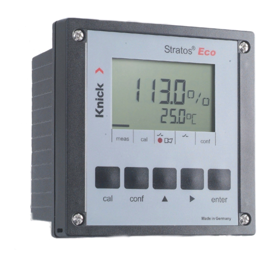
- Page 1 Stratos® Eco 2405 pH User Manual Latest Product Information: www.knick.de...
- Page 2 Please observe the applicable local or national regulations concerning the disposal of “waste electrical and electronic equipment”. Knick Elektronische Messgeräte GmbH & Co. KG Beuckestraße 22 14163 Berlin Germany Phone: +49 30 80191-0 Fax: +49 30 80191-200 Web: www.knick.de Email: info@knick.de...
-
Page 3: Table Of Contents
Table of Contents Safety Information ................. 5 Intended Use ....................7 Registered Trademarks .................7 Quickstart Guides ...................8 Overview of Stratos Eco 2405 pH ..........9 Assembly ..................10 Package Contents ..................10 Mounting Plan ....................11 Pipe Mounting, Panel Mounting .............12 Installation and Connection ............14 Installation Instructions ................14... - Page 4 Table of Contents Controlling a Rinsing Probe ..............56 Connecting a Rinsing System ..............57 Parameters ..................58 Factory Settings of Parameters ...............58 Parameters – Individual Settings ............60 Calibration ..................62 pH Calibration ....................63 Automatic Calibration with Calimatic (BUF -xx-) ......64 Manual Calibration ..................66 Data Entry of Premeasured Electrodes ..........68 Product Calibration ..................69 ORP Calibration ....................70...
-
Page 5: Safety Information
Safety Information Safety information – Be sure to read and observe the following instructions! The device has been manufactured using state of the art technology and it complies with applicable safety regulations. When operating the device, certain conditions may nevertheless lead to danger for the operator or damage to the device. -
Page 7: Intended Use
Intended Use The Stratos Eco 2405 pH is used for pH/mV, ORP, and temperature measurement in industry, environment, food processing, and sewage treatment. The sturdy molded enclosure can be fixed into a control panel or mounted on a wall or at a post. -
Page 8: Quickstart Guides
Safety Instructions In official EU languages and others. • FM and Control Drawings • EC Declarations of Conformity Quickstart Guides More languages on our website: www.knick.de • Installation and Commissioning • Operation • Menu structure • Calibration • Error messages and recommended actions... -
Page 9: Overview Of Stratos Eco 2405 Ph
Overview Overview of Stratos Eco 2405 pH pH / mV / + Output 1 Output 1 Glass electrode temp Reference input – Output 1/2 electrode Auxiliary + Output 2 Output 2 electrode Relay Shield Relay Do not connect Not in use... -
Page 10: Assembly
Assembly Package Contents Check the shipment for transport damage and completeness. The package should contain: • Front unit • Rear unit • Bag containing small parts • CD-ROM with documentation • Specific test report • Passcode sticker 1 Jumper (2 x) 6 Sealing insert (1 x) 2 Washer (1 x), for conduit mounting: 7 Rubber reducer (1 x) -
Page 11: Mounting Plan
Assembly Mounting Plan 1 Cable gland (3 x) 2 Knockouts for cable gland or 1/2“ conduit, ø 21.5 mm (2 knockouts) Conduits not included! 3 Knockout for pipe mounting (4 x) 4 Knockout for wall mounting (2 x) Fig.: Mounting plan (All dimensions in mm!) -
Page 12: Pipe Mounting, Panel Mounting
Assembly Pipe Mounting, Panel Mounting 1 ZU 0276 protective hood (if required) 2 Hose clamp with worm gear drive to DIN 3017 (2 x) 3 Pipe-mount plate (1 x) 4 For vertical or horizontal posts or pipes 5 Self-tapping screw (4 x) Fig.: ZU 0274 pipe-mount kit (All dimensions in mm!) Fig.: ZU 0276 protective hood for wall and pipe mounting (All dimensions in mm!) - Page 13 Assembly 1 Screw (4 x) max. 25 2 Gasket (1 x) 3 Control panel 4 Span piece (4 x) 5 Threaded sleeve (4 x) Panel cut-out 138 x 138 mm (DIN 43700) 1...22 Fig.: ZU 0275 panel-mount kit (All dimensions in mm!)
-
Page 14: Installation And Connection
20.5 ... 253 V AC/DC. • All parameters must be set by a system administrator prior to commissioning. The terminals are suitable for single wires and flexible leads up to 2.5 mm (AWG 14). Terminal Assignments Fig.: Stratos Eco 2405 pH terminal assignments... - Page 15 Installation and Connection 1 ESD shield covering the signal inputs (Screw off for assembly) Note: The cable shield must end under the ESD shield. (Cut lines if required.) 2 Terminals for temperature probe and outer shield 3 Terminals for sensor 4 Power supply connection Fig.: Information on installation, rear side of device Division 2 Wiring...
-
Page 16: Vp Cable Connection
Installation and Connection VP Cable Connection Connecting the sensor to the VP cable ZU 0313: 3 m ZU 0314: 5 m ZU 0315: 10 m Please note: Cable lengths > 20 m can worsen the response during pH measurement. Be sure to observe the sensor instruction manual. -
Page 17: Vp Cable Assignment
Installation and Connection VP Cable Assignment A transparent sensing electrode B red reference electrode C gray D blue auxiliary electrode E white F green S green/yellow outer shield C = 220 nF T1/T2 = Temperature probe for 2-wire connection... -
Page 18: Ph Wiring Examples
Wiring Examples Example 1: pH measurement with monitoring of glass electrode Sensor connections Stratos Eco 2405 pH All common pH sensors can be connected (with glass electrode and separate or combined reference electrode, with or without temperature detector, with nominal zero at pH 7). - Page 19 Example 2: pH measurement with monitoring of glass electrode, without solution ground (SG), VP connection, e.g. SE531, SE532, SE551, SE553, SE538 Sensor connections Stratos Eco 2405 pH All common pH sensors can be connected (with glass electrode and separate or combined reference electrode, with e.g.
- Page 20 Wiring Examples Example 3: pH measurement with monitoring of glass electrode, sensors with solution ground (SG), VP connection, e.g. SE533, SE552 Sensor connections Stratos Eco 2405 pH All common pH sensors can be connected (with glass electrode and separate or combined e.g.
-
Page 21: Orp Wiring Example
ORP Wiring Example Example 4: ORP measurement Sensor connections Stratos Eco 2405 pH All common redox sensors can be con- nected (with separate or combined refer- e.g. ence electrode, with VP cable or without tempera- ZU 0318 ture detector). e.g. -
Page 22: Protective Wiring Of Relay Outputs
Protective Wiring of Relay Outputs Protective Wiring of Relay Contacts Relay contacts are subjected to electrical erosion. Especially with inductive and capacitive loads, the service life of the contacts will be reduced. For suppression of sparks and arcing, components such as RC combinations, nonlinear resistors, series resistors and diodes should be used. - Page 23 Protective Wiring of Relay Outputs Typical Protective Wiring Measures A: DC application with inductive load B: AC/DC applications with capacitive load C: Connection of incandescent lamps (resistive load) A1 Inductive load A2 Free-wheeling diode, e.g. 1N4007 (Observe polarity) A3 Contact B1 Capacitive load B2 Resistor, e.g.
-
Page 24: User Interface And Display
User Interface and Display User Interface 1 Display 2 Alarm LED Mode indicators (no keys), 3 Keypad from left to right: - Measuring mode - Calibration mode - Alarm - Wash contact - Configuration mode... - Page 25 User Interface and Display Display 9 10 1 Passcode entry 14 Secondary display 2 Not in use 15 Manual temperature specification 3 Temperature 16 Hold mode active 4 Current output 17 Waiting time running 5 Limit values 18 Sensor data 6 Alarm 19 Main display 7 Sensocheck...
-
Page 26: Operation: Keypad
User Interface and Display Operation: Keypad Start, end calibration conf Start, end configuration • Select digit position (selected position blinks) • Menu navigation • Edit digit • Menu navigation enter • Calibration: Continue in program sequence • Configuration: Confirm entries, next configuration step •... -
Page 27: Safety Functions
Safety Functions Sensocheck, Sensoface Sensor Monitoring Sensocheck continuously monitors the sensor and its wiring. Sensocheck can be switched off (Configuration, Pg 52). Sensoface provides information on the sensor condition. The asymmetry potential (zero), slope and response time during calibration are evaluated. The three Sensoface indica- tors provide the user with information on wear and required maintenance of the sensor. -
Page 28: Hold Mode
Safety Functions Hold Mode Display: The Hold mode is a safety state during configuration and calibration. Output current is frozen (Last) or set to a fixed value (Fix). Alarm and limit contacts are disabled. If the calibration or configuration mode is exited, the device remains in the Hold mode for safety reasons. - Page 29 Safety Functions Alarm Alarm delay is 10 seconds. During an error message the alarm LED blinks. Error messages can also be signaled by a 22 mA output current. The alarm contact is activated by alarm or power failure, see also Pg 53.
-
Page 30: Configuration
Configuration In the Configuration mode you set the device parameters. Activation conf Activate by pressing conf Enter passcode “1200“ Edit parameter using and , confirm/proceed using enter. (End by pressing conf, then enter.) HOLD The output current is frozen (at its last value or at a preset fixed value, depend- ing on the configuration), limit and During configu-... -
Page 31: Menu Structure Of Configuration
Configuration Menu Structure of Configuration The configuration steps are assigned to different menu groups. Using the arrow keys, you can jump between the individual menu groups. Each menu group contains menu items for setting the parameters. Pressing enter opens a menu item. The values are edited using the arrow keys. -
Page 32: Overview Of Configuration Steps
Configuration Overview of Configuration Steps Code Menu Selection / Default out1 Output 1 o1.UnIT Select process variable pH / ORP o1. rNG Select current range 0-20 mA / 4-20 mA o1. 4mA Enter current start xxxx o1.20mA Enter current end xxxx o1.FtME Time constant of output filter... - Page 33 Configuration Code Menu Selection / Default ALrt Alarm settings AL.SnSO Select Sensocheck ON / OFF rLAY Relay 1: Limit L1.FCT Select contact function Lo / Hi L1.tYP Select contact response N/O / N/C L1.LEVL Enter setpoint xxxx L1.HYS Enter hysteresis xxxx L1.dLY Enter delay...
-
Page 34: Output 1
Configuration Output 1 Process variable (pH/ORP) 1 Press conf key. conf 2 Enter passcode 1200. 3 Output 1 menu group is displayed. All items of this menu group are indicated by the “o1. ” code. 4 Press enter to select menu, edit using arrow keys (see Pg 35). - Page 35 Configuration Code Display Action Choices Select variable pH/ORP pH/ORP Select using arrow key. Press enter to proceed. Note: Characters represented in gray are blinking and can be edited.
- Page 36 Configuration Output 1 Output current range, current start, current end 1 Press conf key. conf 2 Enter passcode 1200. 3 Output 1 menu group is displayed. All items of this menu group are indicated by the “o1. ” code. 4 Press enter to select menu, edit using arrow keys (see Pg 37).
- Page 37 Configuration Code Display Action Choices Set output current range 4 - 20 mA Select usingkey, (0 - 20 mA) press enter to proceed. pH -2 ... 16 Current start Enter lower end of scale, (-1500 mV depending on process variable selected (pH or ORP) +1500 mV) Select usingkey, edit number using key,...
- Page 38 Configuration Output 1 Time constant of output filter 1 Press conf key. conf 2 Enter passcode 1200. 3 Output 1 menu group is displayed. All items of this menu group are indicated by the “o1. ” code. 4 Press enter to select menu, edit using arrow keys (see Pg 39).
- Page 39 Configuration Code Display Action Choices Time constant of output 0 sec filter, default setting: 0 ... 120 sec 0 s (inactive). To specify a time constant: Select using key, edit number using key, press enter to proceed. Time Constant of Output Filter (Attenuation) To smoothen the current output, a low-pass filter with adjustable filter time constant can be switched on.
- Page 40 Configuration Output 1 Output current during Error and HOLD 1 Press conf key. conf 2 Enter passcode 1200. 3 Output 1 menu group is displayed. All items of this menu group are indicated by the “o1. ” code. 4 Press enter to select menu, edit using arrow keys (see Pg 41).
- Page 41 Configuration Code Display Action Choices 22 mA signal for error message (ON) Select usingkey, press enter to proceed. LAST Output signal during HOLD LAST: During HOLD the last (FIX) measured value is main- tained at the output FIX: During HOLD a value (to be entered) is maintained at the output Select usingkey,...
-
Page 42: Output 2
Configuration Output 2 Temperature unit and probe, output current 1 Press conf key. conf 2 Enter passcode 1200. 3 Select Output 2 menu group using arrow keys. All items of this menu group are indi- cated by the “o2. ” code. 4 Press enter to select menu, edit using arrow keys (see Pg 43). - Page 43 Configuration Code Display Action Choices Specify temperature unit °C Select usingkey, (°F) press enter to proceed. Pt1000 Select temperature probe Select usingkey, (Pt100, press enter to proceed. NTC30, NTC8.55, Bco3000) Select output current range 4 - 20 mA Select usingkey, (0 - 20 mA) press enter to proceed.
- Page 44 Configuration Output 2 Time constant of output filter 1 Press conf key. conf 2 Enter passcode 1200. 3 Select Output 2 menu group using arrow keys. All items of this menu group are indi- cated by the “o2. ” code. 4 Press enter to select menu, edit using arrow keys (see Pg 45).
- Page 45 Configuration Code Display Action Choices Time constant of output filter 0 sec Default setting: (0 ... 120 sec) 0 sec (inactive). To specify a time constant: Select using key, edit number using key, press enter to proceed. Time Constant of Output Filter To smoothen the current output, a low-pass filter with adjustable filter time constant can be switched on.
- Page 46 Configuration Output 2 Temperature error, output current during HOLD 1 Press conf key. conf 2 Enter passcode 1200. 3 Select Output 2 menu group using arrow keys. All items of this menu group are indi- cated by the “o1. ” code. 4 Press enter to select menu, edit using arrow keys (see Pg 47).
- Page 47 Configuration Code Display Action Choices 22 mA signal for error (ON) message Select usingkey, press enter to proceed. LAST Output signal during HOLD LAST: During HOLD the last (FIX) measured value is main- tained at the output FIX: During HOLD a value (to be entered) is maintained at the output Select usingkey,...
-
Page 48: Temperature Compensation
Configuration Temperature Compensation Temp detection for meas/cal, TC process medium 1 Press conf key. conf 2 Enter passcode 1200. 3 Select Temperature compensation menu group using arrow keys. All items of this menu group are indicated by the “tc. ” code. 4 Press enter to select menu, edit using arrow keys (see Pg 49). - Page 49 Configuration Code Display Action Choices Select temp detection during measurement (MAN) (Auto/MAN) AUTO: Temp detection with temperature probe MAN: Manual temperature input Select usingkey, press enter to proceed. 25.0 °C Only with manual temp detection selected (MAN): (xxx.x °C) Enter temperature. Select position using...
-
Page 50: Calibration Mode
Configuration Calibration Mode 1 Press conf key. conf 2 Enter passcode 1200. 3 Select Calibration mode menu group using arrow keys. All items of this menu group are indicated by the “CA. ” code. 4 Press enter to select menu, edit using arrow keys (see Pg 51). - Page 51 -04-BUF/ selection. -05-BUF/ To do so, you must select -06-BUF/ your buffer set: -07-BUF/ -08-BUF/ -01- BUF: Mettler-Toledo MAN/ -02-BUF: Knick CaliMat DAT) (Merck Titrisols, Riedel Fixanals) -03- BUF: Ciba (94) -04-BUF: NIST technical buffers -05-BUF: NIST standard buffers -06-BUF:...
-
Page 52: Alarm Settings
Configuration Alarm Settings 1 Press conf key. conf 2 Enter passcode 1200. 3 Select Alarm settings menu group using arrow keys. All items of this menu group are indicated by the “AL. ” code. 4 Press enter to select menu, edit using arrow keys (see Pg 53). - Page 53 Configuration Code Display Action Choices Select Sensocheck ON/OFF (continuous monitoring of glass and reference electrode) Select usingkey, press enter to proceed. Alarm Contact Alarm The alarm contact is closed during normal operation (N/C). It opens in the case of alarm or power outage.
-
Page 54: Limit Function
Configuration Limit Function Relay 1 Press conf key. conf 2 Enter passcode 1200. 3 Select Limit function menu group using arrow keys. All items of this menu group are indicated by the “L1. ” code. 4 Press enter to select menu, edit using arrow keys (see Pg 54). - Page 55 Configuration Code Display Action Choices Contact function (see below for function (HI) principle) Select usingkey, press enter to proceed. Contact response N/C: normally closed contact (N/O) N/O: normally open contact Select usingkey, press enter to proceed. 00.00 pH Setpoint Select usingkey, (xx.xx pH) edit number using key, press enter to proceed.
-
Page 56: Controlling A Rinsing Probe
Configuration Controlling a Rinsing Probe conf “Clean” contact 1 Taste conf drücken. 1 Press conf key. 2 Passcode 1200 eingeben. 2 Enter passcode 1200. 3 Menügruppe Grenzwertfunktion mit 3 Select Rinsing probes menu group using Pfeiltasten auswählen. Für alle Menüpunkte arrow keys. -
Page 57: Connecting A Rinsing System
Configuration Code Display Action Choices Rinsing interval 0.000 h Select using key, enter (x.xxx h) number using press enter to proceed. 0060 s Rinse duration Select using key, (xxxx s) enter number using press enter to proceed. Contact response N/C: normally closed contact N/O: normally open contact... -
Page 58: Parameters
Parameters Factory Settings of Parameters Activation: Simultaneously press conf + right arrow key and enter passcode “4321“. The lower display line reads “Clear“. To prevent accidental resetting, “NO“ is set as default (blinking in the main display). Press one of the arrow keys to select “YES“... - Page 59 Parameters Code Parameters Factory setting tc.MEAS TC measurement Auto tc.MEAS Measuring temp 025.0 °C tc. CAL Calibration Auto tc. CAL Calibration temp 025.0 °C tc. LIN TC medium 00.00 %/K CA. SOL Cal solution -01-BUF CA.tiME Calibration interval 0000 h AL.SnSO Sensocheck L1.FCT...
-
Page 60: Parameters - Individual Settings
Parameters Parameters – Individual Settings Code Parameter Setting o1.UnIT pH/ORP unit o1. rNG 0/4 ... 20 mA o1. 4mA Current start o1.20mA Current end o1.FtME Filter time o1.FAIL 22mA signal o1.HoLD HOLD response o1.FIX Fix current o2.UnIT Unit °C / °F o2.rTD Temp probe o2.rNG... - Page 61 Parameters Parameter Setting Code o2.HoLD HOLD response o2.FIX Fix current tc.MEAS TC measurement tc.MEAS Measuring temp tc. CAL Calibration tc. CAL Calibration temp tc. LIN TC medium CA. SOL Cal solution CA.tiME Cal interval AL.SnSO Sensocheck L1.FCT Contact function L1.tYP Contact response L1.LEVL Setpoint...
-
Page 62: Calibration
Calibration Calibration adjusts the device to the sensor. Activation Activate by pressing cal Enter passcode “1100“ or “1105“ Select using key. Edit parameter using . Press enter to proceed. (End by pressing cal, then enter.) HOLD During calibration the device remains in the Hold mode for reasons of safety. -
Page 63: Ph Calibration
Calibration pH Calibration Calibration is used to adapt the device to the individual sensor char- acteristics, namely asymmetry potential and slope. Calibration can be performed with Calimatic automatic buffer recognition, with manual buffer input, by entering premeasured electrode data, or by sampling the product. -
Page 64: Automatic Calibration With Calimatic (Buf -Xx-)
Calibration Automatic Calibration with Calimatic (BUF -xx-) Automatic or manual temperature detection The device can only operate properly when the buffer solutions used correspond to the configured set. Other buffer solutions, even those with the same nominal values, may demonstrate a different tempera- ture response. - Page 65 Calibration Display Action Remark Calibration with the first buffer is terminated. Remove the sensor and temp probe from the first buffer solution and rinse them thoroughly. • One-point calibration: For one-point End by pressing cal. calibration only: Slope [%] and asymmetry potential [mV] of the sensor are displayed.
-
Page 66: Manual Calibration
Calibration Manual Calibration Automatic or manual temperature detection For calibration with manual buffer specification, you must enter the pH value of the buffer solution used in the device for the proper temperature. This presetting enables calibration with any desired buf- fer solution. - Page 67 Calibration Display Action Remark Calibration with the first buffer is terminated. Remove the sensor and temp probe from the first buffer solution and rinse them thoroughly. • One-point calibration: For one-point End by pressing cal. calibration only: Slope [%] and asymmetry potential [mV] of the sensor are displayed.
-
Page 68: Data Entry Of Premeasured Electrodes
Calibration Data Entry of Premeasured Electrodes You can directly enter the values for slope and asymmetry potential of a sensor. The values must be known, e.g. determined beforehand in the laboratory. The DAT calibration mode must have been preset during configuration. -
Page 69: Product Calibration
Calibration Product Calibration Calibration by comparison Product calibration is a 1-point calibration. During product calibration the sensor remains in the process. Procedure: Open the product calibration menu. Measure the pH value of the process using a reference meter – e.g. in a bypass or in a sample taken from the process. -
Page 70: Orp Calibration
Calibration ORP Calibration ORP calibration mode is automatically preset when ORP measurement is configured. The potential of a redox (ORP) sensor is calibrated using a redox buffer solution. In the course of that, the difference between the measured potential and the potential of the calibration solution is determined according to the following equation. - Page 71 Calibration Display Action Remark Select calibration If an invalid code is Press cal key, entered, the device enter code 1100. returns to measuring Presskey to select position, mode. enter number usingkey, confirm by pressing enter. Remove the sensor and Welcome (2 sec) temperature probe, clean them Device is in Hold and immerse them in the redox...
-
Page 72: Temp Probe Adjustment
Temp Probe Adjustment Display Action Remark Select calibration Wrong settings Press cal key, change the measure- enter code 1015. ment properties! Select position usingkey, If an invalid code is edit number usingkey, entered, the device confirm by pressing enter. returns to measuring mode. -
Page 73: Diagnostics Functions
Diagnostics Functions Display Action Display of output currents Press enter while in measuring mode. The current at output 1 is shown in the main display, the current at output 2 in the secondary display. After 5 sec the device returns to measuring mode. Display of calibration data (Cal Info) Press cal while in measuring mode and confirm code 0000. - Page 74 Diagnostics Functions These functions are used for testing the connected peripherals. Display Action Specify current at output 1 Press conf while in measuring mode and enter code 5555. The current indicated in the main display for output 1 can be edited. Select usingkey, edit number using key.
-
Page 75: Error Messages (Error Codes)
Error Messages (Error Codes) Problem Error Display Possible causes ERR 01 pH sensor Measured value • Sensor defective blinks • Not enough electrolyte in sensor • Sensor not connected • Break in sensor cable • Wrong sensor connected • Measured pH value < -2 or > 16 •... - Page 76 Error Messages (Error Codes) Icon Problem Error (blinks) Possible causes ERR 03 Temperature probe Open or short circuit Temperature range exceeded ERR 11 Current output 1 Current below 0 (3.8) mA ERR 12 Current output 1 Current above 20.5 mA ERR 13 Current output 1 Current span too small / too large...
-
Page 77: Calibration Error Messages
Calibration Error Messages Problem Icon blinks: Possible causes Asymmetry potential out of range (±60 mV) • Sensor worn out • Buffer solutions unusable or contaminated • Buffer does not belong to configured buffer set • Temperature probe not immersed in buffer solution (for automatic temperature compensation) •... - Page 78 Calibration Error Messages Problem Icon blinks: Possible causes Calibration was canceled after approx. 2 minutes because the sensor drift was too large. • Sensor defective • Sensor dirty • No electrolyte in the sensor • Sensor cable insufficiently shielded or defective •...
-
Page 79: Operating States
Operating States Operating status Measure Cal Info 20 s (cal) 0000 Error Info 20 s (conf ) 0000 Calibration (cal) 1100 Temp adjustment (cal) 1015 Product calibration (cal) 1105 Configuration 20 min (conf ) 1200 Sensor monitor 20 min (conf ) 2222 Current source 1 20 min (conf ) 5555... -
Page 80: Sensoface
Sensoface (Sensocheck must have been activated during configuration.) The smiley in the display (Sensoface) alerts to sensor problems (defec- tive sensor, defective cable, maintenance required). The permitted calibration ranges and the conditions for a friendly, neutral, or sad Sensoface are summarized in the following table. Additional icons refer to the error cause. - Page 81 Sensoface Display Problem Status Asymmetry Asymmetry potential (zero) and potential and slope of the sensor are still okay. slope The sensor should be replaced soon. Asymmetry potential and slope of the sensor have reached values which no longer ensure proper calibration.
-
Page 83: Appendix
Appendix Product Line and Accessories Devices Order No. Stratos Eco 2405 pH 2405 pH Mounting Accessories Pipe-mount kit ZU 0274 Panel-mount kit ZU 0275 Protective hood ZU 0276 For more information concerning our sensors and fittings product line, please refer to our website:... -
Page 84: Specifications
< 1 mV TC: 0.1 mV/K pH sensor standardization pH calibration Operating modes BUF Calibration with automatic buffer recognition Calimatic: Buffer sets -01- Knick / Mettler-Toledo 2.00/4.01/7.00/9.21 -02- Merck/Riedel de Haen 2.00/4.00/7.00/9.00/12.00 -03- Ciba (94) 2.06/4.00/7.00/10.00 -04- NIST technical 1.68/4.00/7.00/10.01/12.46... - Page 85 Specifications Calibration with manual entry of individual buffer values Data entry of pre-measured electrodes Max. calibration range Asymmetry potential: ± 60 mV Slope: 80 ... 103 % (47.5 ... 61 mV/pH) ORP sensor standardization ORP calibration Max. calibration range –700 ... +700 ∆mV Calibration timer 0000 ...
- Page 86 Specifications Output 1 0/4 ... 20 mA, max. 10 V, floating (galvanically connected to output 2) Process variable pH or mV value Overrange 22 mA in the case of error messages Output filter Low-pass, filter time constant 0 ... 120 s Measurement error <...
- Page 87 Specifications Cleaning function Relay contact, floating, for controlling a simple rinsing system or an automatic cleaning system Contact ratings AC< 250 V / < 3 A / < 750 VA DC< 30 V / < 3 A / < 90 W Contact response N/C or N/O Rinse interval...
- Page 88 Specifications Power supply 24 (–15%) ... 230 V AC/DC (+10%); approx. 5 VA, 2.5 W, AC: 45 ... 65 Hz Overvoltage category II, protection class II Nominal operating conditions Ambient temperature –20 ... +55 °C Transport/Storage temp –20 ... +70 °C Relative humidity 10…95 % not condensing, maximum operating height 2000 m...
- Page 89 Specifications Cable glands 3 knockouts for cable glands M20x1.5 2 knockouts for NPT 1/2" or rigid metallic conduit Weight Approx.1 kg * User-defined 1) To IEC 746 Part 1, at nominal operating conditions 2) ± 1 count 3) Plus sensor error...
-
Page 90: Buffer Tables
Buffer Tables -01- Mettler-Toledo technical buffers °C 2.03 4.01 7.12 9.52 2.02 4.01 7.09 9.45 2.01 4.00 7.06 9.38 2.00 4.00 7.04 9.32 2.00 4.00 7.02 9.26 2.00 4.01 7.00 9.21 1.99 4.01 6.99 9.16 1.99 4.02 6.98 9.11 1.98 4.03 6.97 9.06... - Page 91 Buffer Tables -02- Knick CaliMat (Merck Titrisols, Riedel-de-Haen Fixanals) °C Order No. CS-P0200A/... CS-P0400A/... CS-P0700A/... CS-P0900A/... CS-P1200A/... 2.01 4.05 7.09 9.24 12.58 2.01 4.04 7.07 9.16 12.39 2.01 4.02 7.04 9.11 12.26 2.00 4.01 7.02 9.05 12.13 2.00 4.00 7.00 9.00...
- Page 92 Buffer Tables Ciba (94) buffers -03- Nominal values: 2.06, 4.00, 7.00, 10.00 °C 2.04 4.00 7.10 10.30 2.09 4.02 7.08 10.21 2.07 4.00 7.05 10.14 2.08 4.00 7.02 10.06 2.09 4.01 6.98 9.99 2.08 4.02 6.98 9.95 2.06 4.00 6.96 9.89 2.06 4.01...
- Page 93 Buffer Tables -04- NIST technical buffers °C 1.67 4.00 7.11 10.32 13.42 1.67 4.00 7.08 10.25 13.21 1.67 4.00 7.06 10.18 13.01 1.67 4.00 7.04 10.12 12.80 1.67 4.00 7.01 10.06 12.64 1.68 4.00 7.00 10.01 12.46 1.68 4.01 6.98 9.97 12.30 1.69...
- Page 94 Buffer Tables NIST standard buffers -05- NIST Standard (DIN 19266 : 2000-01) °C 1.668 4.004 6.950 9.392 1.670 4.001 6.922 9.331 1.672 4.001 6.900 9.277 1.676 4.003 6.880 9.228 1.680 4.008 6.865 9.184 1.685 4.015 6.853 9.144 1.694 4.028 6.841 9.095 1.697 4.036...
- Page 95 Buffer Tables HACH buffers -06- Nominal values: 4.01, 7.00, 10.01 °C 4.00 7.14 10.30 4.00 7.10 10.23 4.00 7.04 10.11 4.00 7.04 10.11 4.00 7.02 10.05 4.01 7.00 10.00 4.01 6.99 9.96 4.02 6.98 9.92 4.03 6.98 9.88 4.05 6.98 9.85 4.06 6.98...
- Page 96 Buffer Tables -07- WTW buffers °C 2.03 4.01 7.12 10.65 2.02 4.01 7.09 10.52 2.01 4.00 7.06 10.39 2.00 4.00 7.04 10.26 2.00 4.00 7.02 10.13 2.00 4.01 7.00 10.00 1.99 4.01 6.99 9.87 1.99 4.02 6.98 9.74 1.98 4.03 6.97 9.61 1.98...
- Page 97 Buffer Tables -08- Hamilton Duracal buffers °C 4.01 7.12 10.19 4.01 7.09 10.19 4.00 7.06 10.15 4.00 7.04 10.11 4.00 7.02 10.06 4.01 7.00 10.01 4.01 6.99 9.97 4.02 6.98 9.92 4.03 6.97 9.86 4.04 6.97 9.83 4.06 6.97 9.79 4.08 * 6.98 * 9.77 *...
-
Page 98: Glossary
Glossary Asymmetry The voltage which a pH sensor provides at a pH potential of 7. The asymmetry potential is different for each sensor and changes with age and wear. Buffer set Contains selected buffer solutions which can be used for automatic calibration with the Calimatic. The buffer set must be selected prior to the first calibration. - Page 99 Glossary One-point Calibration with which only the asymmetry poten- calibration tial (zero point) is taken into account. The previous slope value is retained. Only one buffer solution is required for a one-point calibration. Passcode Preset four-digit number to select certain functions.
- Page 100 Glossary Two-point Calibration with which the sensor asymmetry calibration potential (zero point) and slope are determined. Two buffer solutions are required for two-point calibration. Zero See asymmetry potential...
-
Page 101: Approvals - Canada
Approvals – Canada Warnings and Notes to Ensure Safe Operation WARNING! Do not disconnect equipment unless power has been switched off. CAUTION! Clean only with antistatic moistened cloth. CAUTION! Substitution of components may impair suitability for hazardous locations. • The equipment shall be installed and protected from mechanical impact and ultraviolet (UV) sources. - Page 102 Approvals – Canada CAUTION! Use supply wires suitable for 30 °C above ambient and rated at least 250 V. CAUTION! Use signal wires suitable for at least 250V. OBSERVE THE SPECIFICATIONS OF THE CONTROL DRAWING!
-
Page 103: Index
Index 22 mA signal for error message 41, 47 Accessories 83 Alarm contact 53 Alarm setings 29, 52 Approvals 101 Assembly 10 Buffer set selection 51 Buffer tables 90 Calibration 62 Automatic calibration 64 Calibration mode selection 50 Cal timer interval 50 Data entry of pre-measured electrodes 68 Error messages 77 Manual calibration 66... - Page 104 Index Temperature 42 Temperature error 46 Time constant of output filter 44 Configuration: Rinsing probes 56 Configuration: Temperature compensation 48 Connection 14 CSA warnings and notes 101 Current start / end 37, 43 Device self-test 27 Diagnostics functions 73 Display of calibration data 73 Display of last error message 73 Display of output currents 73 Display of sensor potential 73...
- Page 105 Index Installation 14 Intended use 7 Keypad 26 Measurement 72 Mounting plan 11 Operating states 79 ORP measurement Calibration 70 Wiring example 21 Output filter 38, 44 Overview 9 Overview of configuration steps 32 Package contents 10 Panel mounting 13 Panel-mount kit 13 Parameters Factory settings 58...
- Page 106 Index Relay 54, 56 Relay contacts 22 Rinse contact 56 Rinsing interval 57 Rinsing probes 56 Rinsing system 57 Safety information 5, 101 Self-test 27 Sensocheck 27, 52, 80 Configuration 53 Sensoface 27, 80 Sensor connection VP cable 16 Sensor monitor 73 Short instructions 8 Specifications 84 Temperature compensation 48...
-
Page 107: Passcodes
Passcodes Calibration Key + passcode Menu item Page cal + 0000 CAL info (display of zero,slope) cal + 1100 Calibration (with buffer solution) Product calibration cal + 1105 Temp probe adjustment cal + 1015 Configuration Key + passcode Menu item Page conf + 0000 Error info... - Page 108 Knick Elektronische Messgeräte GmbH & Co. KG Headquarters Beuckestraße 22 • 14163 Berlin Germany Phone: +49 30 80191-0 Fax: +49 30 80191-200 info@knick.de www.knick.de Local Contacts www.knick-international.com Copyright 2020 • Subject to change This document was last updated on April 6, 2020 The latest documents are available for download on our website under the corresponding product description.
Need help?
Do you have a question about the Stratos Eco 2405 pH and is the answer not in the manual?
Questions and answers