Table of Contents
Advertisement
Quick Links
User Manual
Betriebsanleitung
Stratos®Pro
Aktuelle Produktinformation: www.knick.de
Latest Product Information: www.knick.de
Stratos Evo A402
Stratos Pro A2... pH
O
English
deutsch
Betriebsanleitung
Aktuelle Produktinformation:
www.knick.de
The Art of Measuring.
Measurement
A2... PH
2
II 1G Ex ia IIC T3/T4/T6
14163 Berlin
14163 Berlin
SE 706X/1-NMSN
SE 706X/2-NMS
14163 Berlin
BVS 10 ATEX E0
BVS 10 ATEX E089 X
II 1G Ex ia IIC T
SE 706X/1-NM
II 1G Ex ia IIC T3/T4/T6
BVS 10 ATEX E
14163 Berlin
II 1G Ex ia IIC
SE 706X/2-NMSN
14163 Berlin
SE 706X/2-NM
BVS 10 ATEX E089 X
II 1G Ex ia IIC T3/T4/T6
BVS 10 ATEX E
II 1G Ex ia IIC
Advertisement
Table of Contents

Related Manuals for Knick Stratos Evo A402


Summary of Contents for Knick Stratos Evo A402
- Page 1 SE 706X/2-NMSN 14163 Berlin SE 706X/2-NM BVS 10 ATEX E089 X II 1G Ex ia IIC T3/T4/T6 BVS 10 ATEX E II 1G Ex ia IIC Stratos Evo A402 User Manual Betriebsanleitung Stratos Pro A2... pH Measurement Stratos®Pro English deutsch A2...
-
Page 3: Table Of Contents
Table of Contents Basics ..........................5 Documents Supplied ....................6 Introduction ..................7 Overview of the Stratos Evo ............12 Modular Concept..................... 16 Terminal Plate and Rating Plates ............ 17 Installation ..................18 Power Supply, Signal Assignments ..............19 Start-Up ..................... 20 Changing the Measuring Function .......... - Page 4 Table of Contents Configuring the CONTROL Input ............... 72 Configuring the Alarm ................... 76 Configuring the Relay Contacts ................. 80 Protective Wiring of Relay Contacts..............86 PID Controller ......................89 Configuring the WASH Contact ................96 Configuring the Time/Date .................. 98 Calibration ..................100 Slope Calibration in Air ..................102 Slope Calibration in Water ..................103...
-
Page 5: Basics
Basics Subject to change without notice Return of Products Under Warranty Please contact our Service Team before returning a defective device. Ship the cleaned device to the address you have been given. If the device has been in contact with process fluids, it must be decontaminated/ disinfected before shipment. -
Page 6: Documents Supplied
Installation and first steps: • Operation • Menu structure • Calibration • Error messages and recommended actions Specific Test Report Electronic Documentation Manuals + Software Ex Devices: Control Drawings EU Declarations of Conformity Up-to date documentation available on our website: www.knick.de... -
Page 7: Introduction
Introduction Stratos Evo is a 4-wire analyzer for process analysis applications. The analyzer comes as basic device for measurement with digital sensors ( Memosens, optical oxygen measurement, inductive conductivity measurement). All measuring functions are stored in an internal memory. You select a measuring function to configure the analyzer for a specific measuring task. - Page 8 The device provides two parameter sets which can be switched manually or via a control input for different process adaptations or different process conditions. For an overview of parameter sets (original for copy), refer to the CD or www.knick.de. Password protection Password protection (passcode) for granting access rights during operation can be...
- Page 9 Introduction Control inputs I input Current The analog (0) 4 ... 20 mA current input can be used for external pressure or temperature compensation (TAN required). input HOLD HOLD (floating digital control input) The HOLD input can be used for external activation of input the HOLD mode.
- Page 10 Introduction Signal outputs The analyzer provides two 0 (4) ..20 mA current outputs for transmission of mea- sured value and temperature, for example. Relay contacts Four floating relay contacts are available. Current outputs Output 1 The floating current outputs (0) 4 ... 20 mA are used for transmitting measured values.
- Page 11 Stratos Evo: Typical Application...
-
Page 12: Overview Of The Stratos Evo
Overview of the Stratos Evo Package Contents Check the shipment for transport damage and completeness. The package should contain: Front unit, rear unit, bag containing small parts Specific test report Documentation Fig.: Assembling the enclosure 1) Jumper (3 x) 6) Sealing insert (1 x) 2) Washer (1 x), for conduit mounting: 7) Rubber reducer (1 x) Place washer between enclosure and... - Page 13 Overview of the Stratos Evo Mounting Plan, Dimensions 1) Cable gland (3 x) 2) Knockouts for cable gland or ½“ conduit, dia. 21.5 mm (2 knockouts). Conduit couplings not included! 3) Knockout for pipe mounting (4 x) 4) Knockout for wall mounting (2 x) All dimensions in mm Mounting Accessories...
- Page 14 Overview of the Stratos Evo Pipe Mounting, Protective Hood 1) Hose clamp with worm gear drive to DIN 3017 (2 x) 2) Pipe-mount plate (1 x) 3) For vertical or horizontal posts or pipes 4) Self-tapping screw (4 x) Fig.: Pipe-mount kit, accessory ZU 0274 Fig.: Protective hood for wall and pipe mounting, accessory ZU 0737...
- Page 15 Overview of the Stratos Evo Panel Mounting 1) Circumferential sealing (1 x) 2) Screws (4 x) 3) Position of control panel 4) Span piece (4 x) 5) Threaded sleeve (4 x) Cutout 138 x 138 mm (DIN 43700) Fig.: Panel-mount kit, accessory ZU 0738 All dimensions in mm...
-
Page 16: Modular Concept
Modular Concept For connection of Slot for Output 1 analog sensors: measuring Insert interchangeable module module (measuring module) Output 2 Alarm Memosens Wash RS-485 Current input HOLD input Power Control input... -
Page 17: Terminal Plate And Rating Plates
Terminal Plate and Rating Plates Terminal Assignments The terminals are suitable for single or stranded wires up to 2.5 mm (AWG 14). A402N Rating Plate... -
Page 18: Installation
Installation Installation Instructions • Installation of the device must be carried out by trained experts in accordance with this user manual and as per applicable local and national codes. • Be sure to observe the technical specifications and input ratings during installation! •... -
Page 19: Power Supply, Signal Assignments
Power Supply, Signal Assignments Power Supply Connect the power supply for Stratos Evo to terminals 21 and 22 (24 ... 230 V AC, 45 ... 65 Hz / 24 ... 80 V DC) Terminal assignments Memosens connection Brown Green Yellow White / Shield Areas for placing the... -
Page 20: Start-Up
Selecting the Measuring Function Start-Up Upon initial start-up, the analyzer automatically recognizes a connected module and adjusts the software correspondingly. When you replace the measuring module, you must select the corresponding measuring function in the “Service” menu. This does not apply to the connection of Memosens sensors. Here, you will be prompted to select the desired measuring function upon first start-up. -
Page 21: Inserting A Module
Inserting a Module Measuring modules for connection of analog oxygen sensors: The measuring module for the connection of analog oxygen sensors is simply inserted into the module slot. Upon initial start-up, the analyzer automatically recog- nizes the module and adjusts the software correspondingly. When you replace the measuring module, you must select the corresponding measuring function in the “Service”... -
Page 22: Oxy Module
Oxy Module Module for oxygen measurement Order code MK-OXY045... input See the following pages for wiring examples. Terminal plate of oxygen module The terminals are suitable for single or stranded wires up to 2.5 mm (AWG 14). The measuring module comes with a self-adhesive label. -
Page 23: Oxy Wiring Examples
Oxy Wiring Examples Example 1: Measuring task: Oxygen STANDARD Sensors (example): “10“ (e.g., SE 706, InPro 6800) Cable (example): CA/VP6ST-003A (ZU 0313) Jumper! VP 6 VP 6... - Page 24 Oxy Wiring Examples Example 2: Measuring task: Oxygen TRACES (TAN required) Sensors (example): “01“ (e.g., SE 707, InPro 6900) Cable (example): CA/VP6ST-003A (ZU 0313) Jumper! VP 6 VP 6...
- Page 25 Oxy Wiring Examples Example 3: Measuring task: Oxygen SUBTRACES (TAN required) Sensors (example): Type “001”, sensor with guard ring and reference electrode Cable (example): CA/VP6ST-003A (ZU 0313) No jumper! VP 6 VP 6...
-
Page 26: Optical Sensor Wiring Example
Optical Sensor Wiring Example Example 4: Measuring task: Connection of optical sensor (LDO) Sensors (example): SE 740 Cable (example): M12 (e.g., CA/M12-005N485) M12 connection Configuration 1. Connect the sensor as shown above. 2. Switch the analyzer on, open the SERVICE menu (passcode: 5555), and select device type “OXY”. 3. -
Page 27: Memosens Sensors
Documenting and archiving meet the demands of FDA CFR 21 Part 11. Detailed reports can be output as csv export for Excel. MemoSuite is available as accessory and comes in the versions “Basic” and “Advanced”: www.knick.de. Settings and Currently connected sensor:... - Page 28 Connecting a Memosens Sensor Standard connection (sensor A) +3 V Brown Green Yellow White/Transp. For dual devices (2 measuring Areas for placing the channels): screwdriver to pull out the (MK-MS095 module) terminals Connection of sensor B +3 V Brown Green Yellow White Transp.
- Page 29 Memosens Cable CA/MS-... Connecting cable for non-contact inductive digital transmission of measured signals (Memosens). By providing perfect galvanic isolation between sensor and analyzer/transmitter, the Memosens cable prevents measurement interferences. Any effects of humidity and corrosion are prevented. Specifications Material Cable diameter 6.3 mm Length up to 100 m...
- Page 30 Module for 2nd Memosens Channel Module for 2nd Memosens channel Order code MK-MS095... Sensor B “MK-MS“ RS 485 A module RS 485 B Shield Terminal plate of module for 2nd Memosens channel The terminals are suitable for single or stranded wires up to 2.5 mm (AWG 14).
-
Page 31: Operation
Operation Measuring Mode Prerequisite: A Memosens sensor is connected or a measuring module is installed with a corresponding analog sensor connected. After the operating voltage has been connected, the analyzer automatically goes to “Measuring“ mode. To call the measuring mode from another operating mode (e.g., Diagnostics, Service): Hold meas key depressed (>... -
Page 32: The Keys And Their Functions
The Keys and Their Functions Up / Down Left / Right arrows arrows • Menu: • Menu: Increase/decrease a Previous/next numeral menu group • Menu: Selection • Number entry: Move between digits info meas • Retrieve • Return to last information menu level •... -
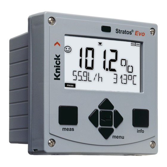
Page 33: The Display
The Display MEMO SENS 1 Temperature 13 Info available 2 Sensocheck 14 HOLD mode active 3 Interval/response time 15 Unit symbols 4 Sensor data 16 Primary process value 5 Sensocheck 17 Secondary display 6 Limit message: 18 Proceed using enter Limit 1 or Limit 2 19 ISM sensor... -
Page 34: Display In Measuring Mode
Display in Measuring Mode The MAIN DISPLAY is the display which is shown in measuring mode. To call the mea- suring mode from any other mode, hold the meas key depressed for at least 2 sec. meas key enter key By pressing meas briefly you can step through further displays such as tag number (TAG) or flow (L/h). -
Page 35: Color-Coded User Interface
Color-Coded User Interface The color-coded user interface guarantees increased operating safety. Operating modes are clearly signaled. The normal measuring mode is white. Information text appears on a green screen and the diagnostic menu appears on turquoise. The orange HOLD mode (e.g., during calibration) is quickly visible as is the magenta screen which indicates asset manage- ment messages for predictive diagnostics –... -
Page 36: Selecting The Mode / Entering Values
Selecting the Mode / Entering Values To select the operating mode: 1) Hold meas key depressed (> 2 s) (measuring mode) 2) Press menu key: the selection menu appears 3) Select operating mode using left / right arrow key 4) Press enter to confirm the selected mode Selection menu Selected mode (blinks) -
Page 37: Operating Modes
Operating Modes Diagnostics Display of calibration data, display of sensor data, sensor monitor, performing a device self-test, viewing the logbook entries, display of hardware/software versions of the individual components. The logbook can store 100 events (00...99). They can be displayed directly on the device. The logbook can be extended to 200 entries using a TAN (Option). - Page 38 HOLD Mode The HOLD mode is a safety state during configuration and calibration. Output current is frozen (LAST) or set to a fixed value (FIX). Alarm and limit contacts are disabled. The display backlighting turns orange, display icon: Output signal response •...
- Page 39 When preset to flow measurement an alarm can be generated when the measured flow exceeds a specified range: (specify value, default: 5 liters/h) (specify value, default: 25 liters/h) CONTROL Power supply (PWR out) 12...24 V AC/DC input Stratos Evo A402...
- Page 40 Operating Modes / Functions Controller Measuring TAG display CLK display parameter display mode (main display (if configured) after 60 s after 60 s selectable) Pressing the menu key (down arrow) opens the selection menu. Select the menu group using the left/right arrow keys. Pressing enter opens a menu item.
-
Page 41: Overview Of Configuration
Overview of Configuration The configuration steps are assigned to different menu groups. Using the left/right arrow keys, you can jump between the individual menu groups. Each menu group contains menu items for setting the parameters. Pressing enter opens a menu item. Use the arrow keys to edit a value. -
Page 42: Switching Parameter Sets A/B
Switching Parameter Sets A/B Parameter Set A/B: Configurable Menu Groups The device provides 2 parameter sets “A“ and “B“. By switching between the parameter sets you can adapt the device to different measurement situations, for example. Parameter set “B“ only permits setting of process-related parameters. -
Page 43: Signaling Parameter Set
Signaling Parameter Set Parameter Set A/B: Manual Switchover Display Action Remark To switch between Manual selection of parameter sets must have been preset in parameter sets: CONFIG mode. Default setting is Press meas a fixed parameter set A. Wrong settings change the measurement properties! PARSET blinks in the lower line. -
Page 44: Connecting A Memosens Sensor
Connecting a Memosens Sensor Step Action/Display Remark Before a Memosens sensor is connected, the error message “NO SENSOR” is displayed. Connect sensor Wait until the sensor data The hourglass in the display blinks. are displayed. Check sensor data Sensoface is friendly when the MEMO SENS sensor data are okay. - Page 45 Replacing a Memosens Sensor Step Action/Display Remark Press menu key to call the Select HOLD mode Now the device is in HOLD mode. The HOLD mode can also A sensor should only be selection menu, be activated externally via the replaced during HOLD select HOLD using the HOLD input.
-
Page 46: Configuring An Oxygen Sensor
Configuring an Oxygen Sensor Device Type: Oxy Connected modules are automatically recognized. When a Memosens sensor is connected at initial start-up, the corre- sponding process variable is loaded and Memosens is config- ured. In the SERVICE menu you can change the device type. Afterwards, you must select the corresponding calibration mode in the CONF menu. - Page 47 Configuring an Oxygen Sensor Menu item Action Select Select sensor type Select sensor type using keys. analog/digital Press enter to confirm. LDO (SE 740 optical sensor) Select measuring mode Select measuring mode using keys. Measurement in liquids GAS: Measurement in gases Press enter to confirm.
- Page 48 Configuring an Oxygen Sensor Sensor, Temperature Unit, Medium: Water/Air, Calibration Timer Press menu key. Select CONF using , press enter. Select parameter set using keys, press enter. Select SENSOR menu using keys, press enter. All items of this menu group are indicated by the “SNS:” code.
- Page 49 Configuring an Oxygen Sensor Menu item Action Select Temperature unit Select temperature unit using keys. Press enter to confirm. Medium: air/water Select calibration medium using keys. AIR: Air as cal medium WTR: Air-saturated water as cal medium Press enter to confirm. Calibration timer Select/deselect calibration timer using ...
- Page 50 Configuring an Oxygen Sensor ISM Sensor, Adaptive Cal Timer (ACT) Press menu key. Select CONF using , press enter. Select parameter set using keys, press enter. Select SENSOR menu using keys, press enter. All items of this menu group are indicated by the “SNS:” code.
- Page 51 Configuring an Oxygen Sensor Adaptive Cal Timer (ACT) By issuing a Sensoface message, the adaptive calibration timer reminds you to calibrate the sensor. After expiration of the interval, Sensoface is getting “sad”. Pressing the info key shows the text “OUT OF CAL TIME CALIBRATE SENSOR” which reminds you that a calibration is due.
- Page 52 Configuring an Oxygen Sensor ISM Sensor, Adaptive Maintenance Timer (TTM) Press menu key. Select CONF using , press enter. Select parameter set using keys, press enter. Select SENSOR menu using keys, press enter. All items of this menu group are indicated by the “SNS:” code.
- Page 53 Configuring an Oxygen Sensor Adaptive Maintenance Timer (TTM, Time to Maintenance) By issuing a Sensoface message, the adaptive maintenance timer reminds you to service the sensor. After expiration of the interval, Sensoface is getting “sad”. Pressing the info key shows the text “OUT OF MAINTENANCE CLEAN SENSOR” which reminds you that a sensor maintenance is due.
- Page 54 Configuring an Oxygen Sensor Sensor, CIP Cleaning Cycles, SIP Sterilization Cycles Press menu key. Select CONF using , press enter. Select parameter set using keys, press enter. Select SENSOR menu using keys, press enter. All items of this menu group are indicated by the “SNS:” code.
- Page 55 Configuring an Oxygen Sensor Menu item Action Select CIP counter Use arrow keys to set the CIP counter: OFF: No counter ON: Fixed cleaning cycle (adjust in the next step) Press enter to confirm. CIP cycles Only with CIP COUNT ON: Enter max.
- Page 56 Configuring an Oxygen Sensor ISM Sensor, Autoclaving Counter Press menu key. Select CONF using , press enter. Select parameter set using keys, press enter. Select SENSOR menu using keys, press enter. All items of this menu group are indicated by the “SNS:” code.
- Page 57 Configuring an Oxygen Sensor Autoclaving Counter After reaching a specified limit value the autoclaving counter generates a Senso- face message. As soon as the counter has reached the specified value, Sensoface is getting “sad”. Pressing the info key shows the text “AUTOCLAVE CYCLES OVERRUN” which reminds you that the maximum number of autoclaving cycles has been reached.
- Page 58 Configuring an Oxygen Sensor Sensor, Sensor Verification (TAG, GROUP) Press menu key. Select CONF using , press enter. Select parameter set using keys, press enter. Select SENSOR menu using keys, press enter. All items of this menu group are indicated by the “SNS:” code.
- Page 59 Configuring an Oxygen Sensor Menu item Action Choices ON/OFF Select ON or OFF using keys. Press enter to confirm. When switched on, the entry for “TAG” in the Memosens sensor is compared to the entry in the analyzer. If the entries differ, a message will be generated.
-
Page 60: Configuration: Overview Tables
Configuration: Overview Tables Device type: Oxy Oxy sensor Choices Default (Select text line) (* requires “Traces“ Option) -400...–1000 mV (0000...–1000 mV for traces) ACT (Adaptive Calibration Timer) (for ISM only) TTM (Time To Maintenance) (for ISM only) - Page 61 Configuration: Overview Tables Configuration (default in bold print) Current output 1 Current output 2 Default setting CHANNEL: TMP (other settings like OT1) Correction MAN / EXT. (with SW-A005 “External current input” option only)
- Page 62 Configuration: Overview Tables Configuration (default in bold print) CNTR_IN input 0 ... 20000 pulses/liter (12000 pulses/liter) Alarm 0 ... 99.9 liters/h (005.0 liters/h) 0 ... 99.9 liters/h (025.0 liters/h) Relay contacts REL1, REL2 The following submenu depends on the selected setting. 000.0 % 0 ...
- Page 63 Configuration: Overview Tables Configuration (default in bold print) PID controller within measuring range 0 ... 50 % full scale Rinse contact WASH Rinse contact / Signaling the active parameter set Selecting the parameter set PARSET (no switchover, parameter set A) (manual selection in the “Configuration”...
-
Page 64: Configuring The Current Output
Configuring the Current Output Output Current, Range, Current Start, Current End Press menu key. Select CONF using , press enter. Select parameter set using keys, press enter. Select OUT1 menu using keys, press enter. All items of this menu group are indicated by the “OT1:“ code. - Page 65 Configuring the Current Output Menu item Action Select Current range Select 4-20 mA or 0-20 mA range using keys. Press enter to confirm. Process variable Example: current output 1, device type OXY Select using keys: OXY: oxygen value TMP: Temperature Press enter to confirm.
- Page 66 Configuring the Current Output Output Current, Time Averaging Filter Press menu key. Select CONF using , press enter. Select parameter set using keys, press enter. Select OUT1 menu using keys, press enter. All items of this menu group are indicated by the “OT1:“ code.
- Page 67 Configuring the Current Output Menu item Action Select Time averaging filter Enter value using keys. Press enter to confirm. Time averaging filter To smoothen the current output, a low-pass filter with adjustable filter time constant can be switched on. When there is a jump at the input (100 %), the output level is at 63 % after the time interval has been reached.
- Page 68 Configuring the Current Output Output Current, Error and HOLD Press menu key. Select CONF using , press enter. Select parameter set using keys, press enter. Select OUT1 menu using keys, press enter. All items of this menu group are indicated by the “OT1:“ code.
- Page 69 Configuring the Current Output Menu item Action Choices Output current during The output current can be set to 22 mA in the case of error mes- error message sages or error messages. Select ON or OFF using keys. Confirm by pressing enter Output current during The output current can be set to 22 mA in the case of Sensoface...
-
Page 70: Correction
Correction Correction Salinity Correction, Pressure Correction Press menu key. Select CONF using , press enter. Select parameter set using keys, press enter. Select CORRECTION menu using keys, press enter. All items of this menu group are indicated by the “COR:” code. - Page 71 Correction Menu item Action Choices Enter salinity Enter the salinity of the process medium. Enter value using keys. Press enter to confirm. Enter pressure unit Select desired pressure unit using keys. Press enter to confirm. Enter pressure correction Select using ...
-
Page 72: Configuring The Control Input
Configuring the CONTROL Input Parameter Set Selection (External Signal) Press menu key. Select CONF using , press enter. Select parameter set A using keys, press enter. Select CNTR_IN menu using keys, press enter. All items of this menu group are indicated by the “IN:” code. - Page 73 Configuring the CONTROL Input Menu item Action Select Select function of Select using keys, confirm by pressing enter CONTROL input (selecting parameter set A/B via signal at CONTROL input) External switchover of parameter sets The parameter set A/B can be activated from outside by sending a signal to the CONTROL input (e.g., from the process control system).
- Page 74 Configuring the CONTROL Input Flow Measurement Press menu key. Select CONF using , press enter. Select parameter set A using keys, press enter. Select CNTR_IN menu using keys, press enter. All items of this menu group are indicated by the “IN:” code.
- Page 75 Configuring the CONTROL Input Menu item Action Select Select function of Select using keys, confirm by pressing enter (selecting parameter set A/B via CONTROL input signal at CONTROL input) (for connecting a pulse-output flow meter) 12000 pulses/liter Adjust to flow meter: With “Flow”...
-
Page 76: Configuring The Alarm
Configuring the Alarm Alarm, Alarm Delay, Sensocheck Press menu key. Select CONF using , press enter. Select parameter set using keys, press enter. Select ALARM menu using keys, press enter. All items of this menu group are indicated by the “ALA:” code. - Page 77 Configuring the Alarm Menu item Action Select Alarm delay Enter alarm delay using keys. Press enter to confirm. Sensocheck Select Sensocheck (continuous monitoring of sensor membrane and lines). Select ON or OFF using keys. Press enter to confirm. (At the same time, Sensoface is activated.
- Page 78 Configuring the Alarm Alarm, CONTROL Input (FLOW MIN, FLOW MAX) Press menu key. Select CONF using , press enter. Select parameter set using keys, press enter. Select ALARM menu using keys, press enter. All items of this menu group are indicated by the “ALA:” code.
- Page 79 Configuring the Alarm Menu item Action Select CONTROL input The CONTROL input can gener- ate an alarm when assigned to “FLOW” (flow monitoring) in the CONF menu: FLOW CNTR Flow measurement: allows monitoring the minimum and maximum flow (pulse counter) Alarm Default: 05.00 liters/h Specify value...
-
Page 80: Configuring The Relay Contacts
Configuring the Relay Contacts Limit Function, Relay 1 Press menu key. Select CONF using , press enter. Select parameter set using , press enter. Select REL1/REL2 menu using keys, press enter. All items of this menu group are indicated by the “RL1:“ code. - Page 81 Configuring the Relay Contacts Menu item Action Select Use of relays Select in the text line using keys: • Limit function (LIMITS) • Controller (CONTROLLER) Note: Selecting CONTROLLER Press enter to confirm. leads to Controller menu group CTR. Select process variable Select desired process variable Depending on module or using ...
- Page 82 Configuring the Relay Contacts Limit Function, Relay 1 Press menu key. Select CONF using , press enter. Select parameter set using keys, press enter. Select REL1/REL2 menu using keys, press enter. All items of this menu group are indicated by the “RL1:“ code.
- Page 83 Configuring the Relay Contacts Menu item Action Choices Limit 1 hysteresis 0...50 % full scale Select hysteresis using keys. Confirm by pressing enter Limit 1 delay The contact is activated with delay (deactivated without delay) Adjust delay using keys.
- Page 84 Configuring the Relay Contacts Limit Function, Relay 2 Press menu key. Select CONF using , press enter. Select parameter set using keys, press enter. Select REL1/REL2 menu using keys, press enter. All items of this menu group are indicated by the “RL2:“ code.
- Page 85 Configuring the Relay Contacts Menu item Action Choices Select process variable Select desired process variable using keys. (CHANNEL) Press enter to confirm. Limit 2 function Select desired function using arrow keys. (FUNCTION) Press enter to confirm. Limit 2 icon: Limit 2 contact type N/O: normally open contact N/C: normally closed contact...
-
Page 86: Protective Wiring Of Relay Contacts
Protective Wiring of Relay Contacts Protective Wiring of Relay Contacts Relay contacts are subject to electrical erosion. Especially with inductive and capac- itive loads, the service life of the contacts will be reduced. For suppression of sparks and arcing, components such as RC combinations, nonlinear resistors, series resistors and diodes should be used. - Page 87 Protective Wiring of Relay Contacts Typical Protective Wiring Measures DC application with inductive load AC/DC applications with capacitive load Connection of incandescent lamps Inductive load Free-wheeling diode, e.g.,1N4007 (Observe polarity) Contact Capacitive load Resistor, e.g., 8 Ω / 1 W at 24 V / 0.3 A Contact Incandescent lamp, max 60 W / 230 V, 30 W / 115 V Contact...
-
Page 89: Pid Controller
PID Controller Typical Applications P controller Application for integrating control systems (e.g., closed tank, batch processes). PI controller Application for non-integrating control systems (e.g., drains). PID controller The additional derivative action compensates for measurement peaks. Controller Characteristic +100 % Controller output Yp Relay 1 Neutral zone Yp=0 Deviation Xw [%]... - Page 90 PID Controller Controller Equations dY P Controller output Y = Y P dt P action I action D action with: Proportional action Reset time [s] Proportional action Y P Rate time [s] Controller gain [%] Setpoint - Meas. value Constant 0 % (for % O or % Air) Y P =...
- Page 91 PID Controller Pulse Length / Pulse Frequency Controller Pulse Length Controller (PLC) The pulse length controller is used to operate a valve as an actuator. It switches the contact on for a time that depends on the controller output. The period is constant. A minimum ON time of 0.5 sec is maintained even if the controller output takes corresponding values.
- Page 92 PID Controller Controller, Process Variable, Controller Type, Setpoint Press menu key. Select CONF using , press enter. Select parameter set using keys, press enter. Select REL1/REL2 menu using keys, press enter. All items of this menu group are indicated by the “CTR:” code.
- Page 93 PID Controller Menu item Action Select Use of relays Select in the text line using keys: • Controller (CONTROLLER) Selecting CONTROLLER leads to Controller menu group CTR. Press enter to confirm. Select process variable Select desired process variable Depending on module or using ...
- Page 94 PID Controller Controller, Neutral Zone, P, I, D Action Components, Behavior during HOLD Press menu key. Select CONF using , press enter. Select parameter set using keys, press enter. Select REL1/REL2 menu using keys, press enter. All items of this menu group are indicated by the “CTR:” code.
- Page 95 PID Controller Menu item Action Select Neutral zone Depending on module or Adjust neutral zone using Memosens sensor keys. Press enter to confirm. Controller: P action Adjust P action using keys. Press enter to confirm. Controller: I action Adjust I action using ...
-
Page 96: Configuring The Wash Contact
Configuring the WASH Contact WASH Contact, Controlling a Rinsing Probe or Signaling the Parameter Set Press menu key. Select CONF using , press enter. Select parameter set A using keys, press enter. Select WASH menu using keys, press enter. All items of this menu group are indicated by the “WSH:”... - Page 97 Configuring the WASH Contact Menu item Action Choices Function Select WASH contact function using keys. WASH: Controlling a rinsing probe With PARSET A/B selected, the contact signals: “Parameter set A“ (open contact) “Parameter set B“ (closed contact) Press enter to confirm. Cleaning interval Only with WASH: Adjust value using ...
-
Page 98: Configuring The Time/Date
Configuring the Time/Date Time and Date, Measuring Point (TAG, GROUP) Press menu key. Select CONF using , press enter. Select parameter set A using keys, press enter. Select CLOCK or TAG using keys, press enter. All items of this menu group are indicated by the “CLK:” or “TAG”... - Page 99 Sensor Verification (Memosens) Time and Date Control of the calibration and cleaning cycles is based on the time and date of the integrated real-time clock. In measuring mode the time is shown in the lower display. When using digital sensors, the calibration data is written in the sensor head.
-
Page 100: Calibration
Calibration Calibration adapts the device to the individual sensor characteristics. For best performance, you should always calibrate in air. Compared to water, air is a calibration medium which is easy to handle, stable, and thus safe. In the most cases, however, the sensor must be removed for a calibration in air. - Page 101 Calibration Common Combination: Process Variable / Calibration Mode Measurement Calibration Application Saturation Water Biotechnology; sensor cannot be removed for calibration (sterility) Concentration Waters, open basins On the following pages, the calibration procedure for a slope calibration in air is described. Of course, other combinations of process variable and calibration mode are possible.
-
Page 102: Slope Calibration In Air
Slope Calibration in Air Display Action Remark Select calibration. “CAL WATER“ or Place sensor in air, “CAL AIR“ is selected in press enter to start. the configuration. Device goes to HOLD mode. Enter relative humidity using Default for relative arrow keys. humidity in air: rH = 50% Press enter to proceed. -
Page 103: Slope Calibration In Water
Slope Calibration in Water Display Action Remark Select calibration (SLOPE). “CAL WATER“ or Immerse sensor in cal “CAL AIR“ is selected in medium, press enter to start. the configuration. Default: 1.013 bar Enter cal pressure. Unit: bar/kpa/PSI Press enter to proceed. Drift check: Display of: Device goes to HOLD sensor current (nA),... -
Page 104: Zero Calibration
Zero Calibration Flawless, amperometric oxygen sensors have a low zero current. Therefore, a zero calibration is only recommended for measurement of oxygen traces. When a zero calibration is performed, the sensor should remain for at least 10 to 30 minutes in the calibration medium (sulfite solution or nitrogen) in order to obtain stable, non-drifting values. - Page 105 Zero Calibration Display Action Remark Select calibration, proceed by pressing enter Ready for calibration. Display (3 sec) Hourglass blinks. Now the device is in Place sensor in oxygen-free HOLD mode. medium Primary display: Wait for the value to zero current. stabilize, can take 10 ...
-
Page 106: Product Calibration
Product Calibration Calibration by Sampling (One-Point Calibration) During product calibration the sensor remains in the process. The measurement process is only interrupted briefly. Procedure: During sampling the currently measured value is stored in the device. The device immediately returns to measuring mode. The cal mode indicator blinks and reminds you that calibration has not been terminated. - Page 107 Product Calibration Display Action Remark The device returns to mea- From the blinking suring mode. CAL mode indicator, you see that product calibration has not been terminated. Product calibration step 2: Display (3 sec) When the sample value has Now the device is in been determined, open the HOLD mode.
-
Page 109: Ldo Calibration
LDO Calibration Calibrating/Adjusting the SE 740 Optical Oxygen Sensor Every oxygen sensor has its individual slope (Stern-Volmer constant cvs) and its indi- vidual zero point (phase angle). Both values are altered, for example, by aging. For sufficiently high accuracy of oxygen measurement, the analyzer must be regu- larly adjusted for the sensor data (adjustment). -
Page 110: Ldo Slope Calibration In Air
LDO Slope Calibration in Air Automatic Calibration in Air The slope is corrected using the saturation value (100 %), similar to air saturation of water. Since this analogy only applies to water-vapor saturated air (100 % relative humidity) and often the calibration air is less humid, the relative humidity of the calibration air must also be specified. - Page 111 LDO Slope Calibration in Air Display Action Remark Select calibration. “CAL WATER“ or Place sensor in air, “CAL AIR“ is selected in press enter to start. the configuration. Device goes to HOLD mode. Enter relative humidity using Default for relative arrow keys. humidity in air: rH = 50% Press enter to proceed.
-
Page 112: Ldo Slope Calibration In Water
LDO Slope Calibration in Water Automatic Calibration in Water The slope is corrected using the saturation value (100 %) of water in equilibrium with air. NOTICE! The calibration medium must be in equilibrium with air. Oxygen exchange between water and air is very slow. Therefore, it takes a relatively long time until water is saturated with atmospheric oxygen. - Page 113 LDO Slope Calibration in Water Display Action Remark Select calibration (SLOPE). “CAL WATER“ or Immerse sensor in cal “CAL AIR“ is selected in medium, press enter to start. the configuration. Default: 1.013 bar Enter cal pressure Unit: bar/kpa/PSI Press enter to proceed. Drift check: Display of: Device goes to HOLD Partial pressure (hPa)
-
Page 114: Ldo Zero Calibration In N
LDO Zero Calibration in N Zero Correction For trace measurements below 500 ppb, the zero point should be calibrated. If you want to perform a zero correction, then you should keep the sensor in the cal- ibration medium (eg, N or sulfite solution) until the measured value has stabilized. - Page 115 LDO Zero Calibration in N Display Action Remark Select calibration. “Zero Point” is selected Place sensor in N in the configuration. press enter to start. Device goes to HOLD mode. Drift check: The drift check can take Display of: some minutes. partial pressure (hPa), response time (s), temperature (°C/°F)
-
Page 116: Ldo Product Calibration
LDO Product Calibration Product Calibration (Calibration with Sampling) When the sensor cannot be removed – e.g. for sterility reasons – its slope can be determined with “sampling”. To do so, the currently measured process value is saved by the analyzer. Directly afterwards, you determine a reference value using a porta- ble meter, for example. - Page 117 LDO Product Calibration Display Action Remark Ready for calibration. Display (3 sec) Hourglass blinks. Press enter to proceed. Press enter to save the measured value and to determine the actual oxygen value. The device returns to From the blinking CAL measuring mode.
-
Page 118: Ldo Offset Correction
LDO Offset Correction When measuring in the oxygen trace range, you can use the product calibration menu to adjust an offset. The offset can only be determined for measured values < 20 mbar. For higher values, the analyzer corrects the slope and adjusts the Stern-Volmer constant in the sensor. -
Page 119: Temp Probe Adjustment
Temp Probe Adjustment Display Action Remark Select CAL_RTD calibration Wrong settings change method. the measurement Press enter to proceed. properties! Measure the temperature of Display (3 sec) the process medium using Now the device is in an external thermometer. HOLD mode. Enter the measured tem- Display of actual perature value. -
Page 120: Measurement
Measurement Display Remark From the configuration or calibration menus, you can switch the device to measuring mode by pressing the meas key. In the measuring mode the upper display line shows the configured process variable (%, mg/l, ppm or tem- or AM/PM and °F: perature), the lower display line shows the time and the second configured process variable (%, mg/l, ppm... - Page 121 Display in Measuring Mode The MAIN DISPLAY is the display which is shown in measuring mode. To call the mea- suring mode from any other mode, hold the meas key depressed for at least 2 sec. meas key enter key meas By pressing meas briefly you can step through further displays such as tag number (TAG) or...
- Page 122 Color-Coded User Interface The color-coded user interface guarantees increased operating safety. Operating modes are clearly signaled. The normal measuring mode is white. Information text appears on a green screen and the diagnostic menu appears on turquoise. The orange HOLD mode (e.g., during calibration) is quickly visible as is the magenta screen which indicates asset manage- ment messages for predictive diagnostics –...
- Page 123 Measurement Display Remark With activated controller you can also step through the following displays by pressing the meas key. When no key has been pressed for 60 sec, the device returns to the standard display. Upper display: Controller output Y The controller output can be modified using .
-
Page 124: Diagnostics
Diagnostics In the Diagnostics mode you can access the following menus without interrupting the measurement: Viewing the calibration data Viewing the sensor data Starting a device self-test Viewing the logbook entries Displaying currently measured values Displaying device type, software version, serial number Access to diagnostics can be protected with a passcode (SERVICE menu). - Page 125 Diagnostics Display Menu item Displaying the calibration data Select CALDATA using, confirm by pressing enter. Use the keys to select the desired parameter from the bottom line of the display (LAST_CAL ZERO SLOPE OFFSET (LDO) NEXT_CAL). The selected parameter is shown in the upper display line.
- Page 126 Diagnostics Display Menu item Device self-test (To abort, you can press meas.) MEMO SENS 1) Display test: Display of all segments with chang- ing background colors (white/green/red). Proceed by pressing enter 2) RAM test: Hourglass blinks, then display of --PASS-- or --FAIL-- Proceed by pressing enter 3) EEPROM test: Hourglass blinks, then display of --PASS-- or --FAIL--...
- Page 127 Diagnostics Display Menu item Displaying the logbook entries Select LOGBOOK using, press enter to confirm. With the keys, you can scroll backwards and forwards through the logbook (entries -00-...-99-), -00- being the last entry. If the display is set to date/time, you can search for a particular date using the ...
- Page 128 Diagnostics Display Menu item Displaying the currently measured values (sensor monitor) , press enter to confirm. Select MONITOR using Use the keys to select the desired parameter from the bottom line of the display: OXY RTD I-INPUT (for digital sensors also: OPERATION TIME ACT (adap- tive cal timer) TTM (adaptive maintenance timer) DLI (Dynamic Life Time Indicator) CIP SIP AUTO-...
-
Page 129: Service
Service In the Service mode you can access the following menus: MONITOR Displaying currently measured values SENSOR Displaying the sensor data, with MEMOSENS also resetting the sensor wear counter after replacement of electrolyte/membrane; ISM only: resetting TTM; ISM/LDO: incrementing the autoclaving counter POWER OUT Power output (adjustable: 3.1/12/15/24 V) OUT1... - Page 130 Service Menu item Remark Displaying currently measured values (sensor monitor) with HOLD mode activated: Select MONITOR using, press enter to confirm. Select variable in the bottom text line using. The selected parameter is shown in the upper dis- play line. As the device is in HOLD mode, you can perform validations using simulators without influencing the signal outputs.
- Page 131 Service Menu item Remark Specifying the current for outputs 1 and 2: Select OUT1 or OUT2 using thekeys, press enter to confirm. Enter a valid current value for the respective output using keys. Confirm by pressing enter. For checking purposes, the actual output current is shown in the bottom right corner of the display.
- Page 132 Service Menu item Remark Assigning passcodes: In the “SERVICE - CODES“ menu you can assign pass- codes to DIAG, HOLD, CAL, CONF and SERVICE modes (Service preset to 5555). When you have lost the Service passcode, you have to request an “Ambulance TAN“ from the man- ufacturer specifying the serial number and hardware version of your device.
-
Page 133: Operating Error
Operating Error! Power Disruption while Loading the Process Variable In very rare cases it seems that the analyzer cannot be operated because it remains in “Firmware Update” mode – indicated by the --FIRMW UPDATE-- message. This occurs when the power is disrupted while the process variable is loaded. - Page 134 Operating Error! Action Key/Display Remark Searching for Then the analyzer searches for a mea- the process suring module or Memosens sensor. variable Loading the When a module or a sensor has been process variable, found, the loading progress is shown automatic in percentages.
-
Page 135: Error Messages
Error Messages Info text Problem Error (is displayed in case of fault when Possible causes the Info key is pressed) ERR 01 NO SENSOR Sensor error Device type not assigned Defective sensor Sensor not connected Break in sensor cable ERR 02 WRONG SENSOR Wrong sensor ERR 04 SENSOR FAILURE Failure in sensor... - Page 136 Error Messages Info text Problem Error (is displayed in case of fault when Possible causes the Info key is pressed) ERR 95 SYSTEM ERROR System error Restart required. If error still persists, send in the device for repair. ERR 97 WRONG MODULE Module does not correspond to measuring function Correct the setting in the...
- Page 137 Error Messages Info text Problem Error (is displayed in case of fault when Possible causes the Info key is pressed) ERR 102 INVALID PARAMETER U-POL Configuration error Polarization voltage ERR 103 INVALID PARAMETER Configuration error MEMBR. COMP Membrane correction ERR 104 INVALID PARAMETER Configuration error CONTROLLER Controller...
-
Page 138: Sensocheck And Sensoface
Sensocheck and Sensoface Sensocheck, Sensoface Sensor Monitoring Sensocheck continuously monitors the sensor and its wiring. The three Sensoface indicators provide information on required maintenance of the sensor. Additional icons refer to the error cause. Pressing the info key shows an information text. Note: The worsening of a Sensoface criterion leads to the devaluation of the Sensoface indicator (Smiley gets “sad”). -
Page 139: Operating States
Operating States Operating status Measure DIAG 60 s HOLD CONF SERVICE SERVICE OUT 1 SERVICE OUT 2 SERVICE RELAIS SERVICE (CODES, DEVICE TYPE; OPTION) Cleaning function Explanation: as configured (Last/Fix or Last/Off ) active manual... -
Page 140: Product Range
Product Range Devices (basic digital devices) Order No. Stratos Evo A402N A402N Stratos Evo A402B (operation in hazardous locations, Zone 2) A402B Interchangeable modules for measurement with analog sensors or 2nd Memosens channel MK-PH015N MK-OXY045N Cond MK-COND025N CondI MK-CONDI035N Cond-Cond MK-CC065N 2nd Memosens channel MK-MS095N... - Page 141 Order No. Pipe-mount kit ZU 0274 Panel-mount kit ZU 0738 Protective hood ZU 0737 M12 socket for sensor connection ZU 0860 with Memosens cable / M12 connector Up-to-date information: www.knick.de Phone: +49 30 80191-0 Fax: +49 30 80191-200 Email: knick@knick.de...
-
Page 143: Specifications
Specifications Standard Sensors: SE 706, InPro 6800, Oxyferm Input range Measuring current 0 ... 600 nA Resolution 10 pA Measurement error < 0.5 % meas. val. + 0.05 nA + 0.005 nA/K Operating modes Measurement in gases Measurement in liquids Display ranges Saturation (–10 ... - Page 144 Specifications Measuring ranges with trace sensors “001“ (TAN SW-A004) Saturation (–10 ... 80°C) 0.000 ... 150.0 % Concentration (–10 ... 80°C) 000.0 ... 9999 µg/l / 10.00 ... 20.00 mg/l (Dissolved oxygen) 000.0 ... 9999 ppb / 10.00 ... 20.00 ppm Volume concentration in gas 000.0 ...
- Page 145 Specifications Sensor standardization * Operating modes * CAL_AIR Automatic calibration in air CAL_WTR Automatic calibration in air-saturated water P_CAL Product calibration CAL_ZERO Zero calibration Calibration range Zero point ± 2 nA Standard sensor “10“ Slope 25 ... 130 nA (at 25 °C, 1013 mbar) Calibration range Zero point ±...
- Page 146 Specifications Input for Memosens or optical sensors (SE 740) Data In/Out Asynchronous interface, RS-485, 9600/19200 Bd Power supply Terminal 1: +3.08 V/10 mA, Ri < 1 ohm, short-circuit-proof Terminal 5: 3.1 … 24 V/1W in four discrete levels (3.1/12/15/24 V), short-circuit-proof (levels are software-selectable), 15 V automatic with SE 740 sensor selected I input (TAN)
- Page 147 Specifications Power Out Power supply output for operating optical sensors (SE 740), Power supply selectable between 3.1 V / 12 V / 15 V / 24 V, short-circuit-proof (for SE 740 fixed to 15 V), max. power 1 W Alarm contact Relay contact, floating Contact ratings AC <...
- Page 148 Parameters, calibration data, logbook > 10 years (EEPROM) Electrical safety Protection against electric shock by protective separation of all extra- low-voltage circuits against mains according to EN 61010-1 Explosion protection see Control Drawing or www.knick.de (A402B) EN 61326 Emitted interference Class B (residential environment)
- Page 149 Specifications HART communication Digital communication via FSK modulation of output current 1 Device identification, measured values, status and messages, parameter setting, calibration, records Conditions Output current ≥ 3.8 mA and load resistance ≥ 250 ohms user-defined according to IEC 746 Part 1, at normal operating conditions...
-
Page 150: Index
Index Accessories 141 ACT (adaptive cal timer, ISM sensors), Oxy 50 Activate Sensocheck 77 Adaptive cal timer (Oxy) 50 Adaptive maintenance timer (Oxy) 52 Adaptive maintenance timer, resetting 130 Adjusting the temp probe 119 Alarm and HOLD messages 39 Alarm, contact characteristics 77 Alarm, CONTROL input 78 Alarm, delay 76 Alarm, description 39... - Page 151 Index Configuration, current output 64 Configuration, limit function 80 Configuration, measuring point (TAG/GROUP) 98 Configuration, oxygen sensor 46 Configuration, pulse frequency controller (PFC) 93 Configuration, pulse length controller (PLC) 93 Configuration, relay contacts 80 Configuration, Sensocheck 76 Configuration, time and date 98 Configuration, time averaging filter 66 Configuration, WASH contact 96 Connecting a Memosens sensor, menu 44...
- Page 152 Index Diagnostics, hardware and software version 128 Diagnostics, logbook 127 Diagnostics mode 124 Diagnostics, sensor data 125 Diagnostics, sensor monitor 128 Digital sensors (Oxy), select sensor type 47 Dimension drawings 13 Display 33 Display backlighting 35 Displaying the time/date 120 Display in measuring mode 34 Display output current 120 Display, selecting the main display 34...
- Page 153 Index HOLD, behavior of PID controller 91 HOLD, configure output current 68 HOLD, exit 38 HOLD, external activation 38 HOLD mode 38 HOLD, output signal during HOLD 38 HOLD, output signal response 38 Hysteresis, application 83 Icons 33 Inductive loads, protective wiring of relay contacts 86 Info text 135 Inserting a module 21 Installation, terminal assignments 18...
- Page 154 Index MAIN DISPLAY 34 Manual pressure input (Oxy) 70 Measured values, viewing (sensor monitor) 128 Measuring function (device type) 132 Measuring mode 120 Measuring mode, general 31 Measuring modules, product range 140 Measuring oxygen, standard 23 Measuring oxygen, subtraces (Option) 25 Measuring oxygen, traces (Option) 24 Measuring point, TAG/GROUP 98 Measuring range and output current 65...
- Page 155 Index Optical oxygen sensor, calibration 109 Options, enabling 132 Order codes 140 Output current during Error and HOLD 68 Output current, range 65 Output currents, display 120 Output current, time averaging filter 66 Output current value, Service mode 131 Output filter, time interval 66 Output signal, controller behavior 94 Output signal during HOLD 69 Output voltage, adjusting (POWER OUT) 130...
- Page 156 Index POWER OUT, adjusting the output voltage 130 Power supply, connection 19 Power supply ratings 19 Pressure correction 70 Process variable not loaded 133 Process variable selection 65 Product calibration 106 Product calibration (LDO) 116 Product range 140 Protective hood 14 Protective wiring of relay contacts 86 Pulse frequency controller (PFC) 91 Pulse frequency controller (PFC), configuration 93...
- Page 157 Index Sensor data, display 125 Sensor monitor, displaying the currently measured values 128 Sensor monitor, Service mode 130 Sensor replacement 45 Sensor verification (TAG, GROUP) 58 Serial number, display 128 Series resistors 86 Service, activating an option 132 Service, factory settings 132 Service, incrementing the autoclaving counter 130 Service life of contacts 86 Service mode 129...
- Page 158 Index Terminal assignments 19 Terminal plate of device 17 Time and date, usage 99 Time averaging filter 67 Time, display 120 Time format, setting 98 Time, setting 98 TRACES, measuring oxygen traces 24 TTM, configure adaptive maintenance timer (Oxy) 52 WASH contact (configuration) 96 WASH contact (signaling parameter set) 43 Wiring 19...
- Page 160 Knick Elektronische Messgeräte GmbH & Co. KG Beuckestraße 22 14163 Berlin Germany Phone: +49 30 80191-0 Fax: +49 30 80191-200 Web: www.knick.de Email: info@knick.de 090874 Stratos Evo A402: O2 Measurement TA-212.101-oxy-KNE02 20170831 Software version: 1.x...
Need help?
Do you have a question about the Stratos Evo A402 and is the answer not in the manual?
Questions and answers