Table of Contents
Advertisement
Quick Links
WIDOS
Einsteinstr. 5
Wilhelm Dommer Söhne
D-71254 Ditzingen-Heimerdingen
GmbH
Website: www.widos.de
Working instructions
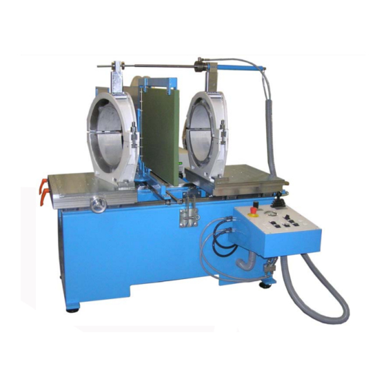
Heating element butt welding machine
15°-clamping tool, additional cylinder and T-90° / T-60° / T-45° (option)
Headquarters: D-71254 Ditzingen-Heimerdingen Country court Stuttgart HRB 200973 Managing directors: Jürgen Dommer, Dr. Kai Dombrowski
Phone
Fax
Email:
Translation
WIDOS 5000 WM
Keep for further use!
+49 (0) 71 52 99 39 0
+49 (0) 71 52 99 39 40
info@widos.de
Advertisement
Table of Contents

Related Manuals for widos 5000 WM


Summary of Contents for widos 5000 WM
- Page 1 Working instructions Translation Heating element butt welding machine WIDOS 5000 WM 15°-clamping tool, additional cylinder and T-90° / T-60° / T-45° (option) Keep for further use! Headquarters: D-71254 Ditzingen-Heimerdingen Country court Stuttgart HRB 200973 Managing directors: Jürgen Dommer, Dr. Kai Dombrowski...
- Page 2 Address of manufacturer WIDOS Wilhelm Dommer Söhne GmbH Einsteinstrasse 5 D-71254 Ditzingen-Heimerdingen Phone: +49 (0) 71 52 99 39 0 Telefax: +49 (0) 71 52 99 39 40 Website: www.widos.de E-mail: info@widos.de 23.06.2015 Working instructions WIDOS 5000 WM Page 2 of 80...
- Page 3 Therefore the searched information can be easily found. 6/23/2015 WIDOS W. Dommer Söhne GmbH Einsteinstraße 5 D-71254 Ditzingen-Heimerdingen All rights reserved Reprinting only allowed with permission of the corporation. Any changes prior to technical innovations. 23.06.2015 Working instructions WIDOS 5000 WM Page 3 of 80...
-
Page 4: Table Of Contents
Safety measures............................. 7 1.3. Conformity............................... 7 1.4. Marking of product............................8 1.4.1. Technical data ................................8 1.4.1.1. WIDOS 5000 WM general data ........................8 1.4.1.2. Basic unit ................................8 1.4.1.3. Heating element ..............................9 1.4.1.4. Planer ..................................9 1.4.1.5. Hydraulic aggregate ............................9 1.5. - Page 5 Transport................................49 8.2. Maintenance, Inspection and repair ......................49 8.3. Clamping elements ............................50 8.4. Planer ................................50 8.5. How to check the oil level / how to refill.....................50 8.5.1. Used hydraulic oil................................. 51 23.06.2015 Working instructions WIDOS 5000 WM Page 5 of 80...
- Page 6 Contens 8.6. Service unit..............................51 8.7. Protect machine parts against corrosion....................51 8.8. Disposal .................................51 ELECTRIC, HYDRAULIC AND PNEUMATIC DIAGRAMS ............... 52 DECLARATION OF CONFORMITY ...................... 80 23.06.2015 Working instructions WIDOS 5000 WM Page 6 of 80...
-
Page 7: Description Of Product
1.1. Usage and purpose-oriented use The WIDOS 5000 WM is a workshop machine for heating element butt welding of pipes and fittings OD = 160 – 500 mm. (Standard-OD: 160 / 180 / 200 / 225 / 250 / 280 / 315 / 355 / 400 / 450 / 500 mm). -
Page 8: Marking Of Product
Technical data All important technical data of the single components are listed. They permit a rapid information about output and structure. 1.4.1.1. WIDOS 5000 WM general data Material: PP; PE, PVDF Size of the pipe: OD = 160 – 500 mm Power: 400 V (±... -
Page 9: Heating Element
Heating cartridge Ø 16 x 640 / 800 W / 230 V; AL 0,5 m on request Temperature probe PT 1000 H09082 Blade 120 mm MES120 Blade 170 mm MES170 Flat-head screw M 3x8 (DIN 965) with Torx-drive 0965C008X Hydraulic oil HLDP35 23.06.2015 Working instructions WIDOS 5000 WM Page 9 of 80... -
Page 10: Tools And Accessories
Attention! Hand over the key to authorized personnel only. each 1 Fork wrench size 22 / 30 Socket spanner size 30 Allan key with T-grip size 8 Allan key tilted size 5 23.06.2015 Working instructions WIDOS 5000 WM Page 10 of 80... -
Page 11: Safety Rules
T h e a c c i d e n t p r e v e n t i o n m e a s u r e s a r e v a l i d ( U V V ) . 23.06.2015 Working instructions WIDOS 5000 WM Page 11 of 80... -
Page 12: Obligations Of The Owner
It must be clearly defined who is responsible for transport, mounting and dismounting, and starting the operation. A person who is being trained may only work at the machine under supervision of an experienced person. 23.06.2015 Working instructions WIDOS 5000 WM Page 12 of 80... -
Page 13: Dangers While Handling The Machine
2.7. Dangers while handling the machine The machine WIDOS 5000 WM is constructed according to the latest technical standard and the acknowledged technical safety rules. However, dangers for the operator or other persons standing nearby may occur. Also material damages are possible. -
Page 14: Danger Of Crushing Between Machine Tables / Clamping Tools
Favorably pass the line and hose in order that the danger is minimized. Do not squeeze and kink the lines or anything likewise. 2.10.5. Risk of injury by noises Noises exceeding 80 dB (A) may occur; during planing it is obligatory to wear ear protection! 23.06.2015 Working instructions WIDOS 5000 WM Page 14 of 80... -
Page 15: Structural Modifications On The Machine
Machine parts which are not in a perfect condition are to be immediately replaced. Only use original WIDOS spare and wear parts. In case of purchase orders please always indicate the machine number! 2.12. -
Page 16: Functional Description
They are put together with the prescribed welding pressure and then cool down under pressure (cooling time). The welding connection can now be unclamped: the welding process is completed. Heating element heats the pipes up to welding temperature. Welded pipe with inside and outside bead. 23.06.2015 Working instructions WIDOS 5000 WM Page 16 of 80... -
Page 17: Operating And Indicating Elements
Service unti and pneumatic valves Right table Operator panel with scanner and emergency-off switch Holder for additional cylinder Distributor block for connecting additional cylinder Adjusting screw for aligning the machine 23.06.2015 Working instructions WIDOS 5000 WM Page 17 of 80... -
Page 18: How To Work With The Optional Additional Cylinder
Distance between flanges and fork: appr. 20-30 mm Holder You must remove the cylinder and put it on its holder at the right side after welding and before you open the clamping tools. 23.06.2015 Working instructions WIDOS 5000 WM Page 18 of 80... -
Page 19: Elements On The Operating Panel
Switch – <planer> on (1) / off (0) Sensor <Planer out>, drive planer out of machine Sensor – <Planer in> drive planer into machine * Please keep buttons pressed until the tools have reached their final position. 23.06.2015 Working instructions WIDOS 5000 WM Page 19 of 80... -
Page 20: Emergency - Stop - Switch
(arrow). Loosen the clamping lever and than turn the handwheel for makeing the misalignment compensation. Tighten the locking lever again. Clamping lever (2 pieces) Hand wheel 23.06.2015 Working instructions WIDOS 5000 WM Page 20 of 80... -
Page 21: Service Unit And Pneumatic Valves
Turn the pressure setting button until the desired pressure is shown on the manometer. The input pressure must be at least 1 bar higher than the output pressure. Press the pressure setting button downwards (towards the housing) to secure it against unintentional turning. 23.06.2015 Working instructions WIDOS 5000 WM Page 21 of 80... -
Page 22: Switch Cabinet
(3 pcs.) Circuit breaker B 16 A; heating element FC40 Motor protection switch 2,8 – 4,0 A; planer Switching power supply 24 V QA10 Hydraulic pump contactor QA20 Heating element contactor QA40 Planer contactor 23.06.2015 Working instructions WIDOS 5000 WM Page 22 of 80... -
Page 23: Main Switch
Connecting screw Reduction insert OD = 450 Pan head screw M 10 x 30 DIN 912 Reduction insert OD = 400 Pan head screw M 10 x 35 DIN 912 23.06.2015 Working instructions WIDOS 5000 WM Page 23 of 80... -
Page 24: Small Clamping Tools (Optional)
The small clamping tools are each screwed to the Grip machine table with washers and hexagon-head screws. Clamping tool closed (with clamped stub end holder) Clamping tool open Spindle, pressure washer and clamping nut 23.06.2015 Working instructions WIDOS 5000 WM Page 24 of 80... -
Page 25: Reduction Inserts And Pipe Supports (Optional)
Place the pipe support with OD 315- 400 mm on the pipe support OD 450 Place the pipe support with OD 160- 280 mm on the pipe support OD 315 23.06.2015 Working instructions WIDOS 5000 WM Page 25 of 80... -
Page 26: Stub End Holder (Optional)
Turn the hexagon nuts and clamp the end cap / cap / flange with the clamping jaws. After welding first release the spindles at the stub end holder. 23.06.2015 Working instructions WIDOS 5000 WM Page 26 of 80... -
Page 27: Clamping Tool On Machine Table
Only turning points „A“ and „B“ on the left machine table. 4.9.1. Clamping tools for straight pipes Mount the clamping tools on turning point „A“. Left clamping tool Right clamping tool 23.06.2015 Working instructions WIDOS 5000 WM Page 27 of 80... -
Page 28: Swivelling Clamping Tools For Angles And Bends
In order to weld more angles, you must shift clamping tools at the turning point. Detach clamping claws, remove screw at turning point and swing clamping tool onto the desired angle (arrows). Afterwards retighten turning points and screw tools into the clamping claws. 23.06.2015 Working instructions WIDOS 5000 WM Page 28 of 80... -
Page 29: Starting And Operating
Unpack the machine, remove packing material. Grab machine on the front e. g. by a forklift and take to destination. Screw the six leveling feet (packed in cardboard) into the machine feet. Put down and align machine on its feet. Machine tables must be horizontal. 23.06.2015 Working instructions WIDOS 5000 WM Page 29 of 80... -
Page 30: How To Set The Heating Element Temperature
As soon as the main switch is activated, the heating element is heated up to the set welding temperature by means of the temperature controller (reference value PEHD: 210 °C, also see chapter 5.3). The temperature controller displays the current temperature. 23.06.2015 Working instructions WIDOS 5000 WM Page 30 of 80... -
Page 31: How To Clamp The Pipes
+ clamping nuts + pressure discs (chapter: 4.6 / 4.7). In case of long pipes use WIDOS roller stands for the alignment resp. in case of small clamping tools use pipe brackets together with the pipe supports (chapter: 4.7.1). -
Page 32: Mismatch Compensation
Important! Set switch < > off, the control lamp < > extinguishes. 23.06.2015 Working instructions WIDOS 5000 WM Page 32 of 80... -
Page 33: Joining
Welding 60 T (chamfered pipe with 60°): 2,00 Welding 45 T (chamfered pipe with 67,,5°): 2,61 Add the motional pressure as usual. All the other welding parameters remain as usual. 23.06.2015 Working instructions WIDOS 5000 WM Page 33 of 80... -
Page 34: How To Weld Segmented Bends
Example 1: bend of 90° 4 segments (6 welding surfaces) 90° sawing angle = ----- = 15° Example 2: bend of 45° in 3 segments (4 welding surfaces) 45° sawing angle = ----- = 11,25° 23.06.2015 Working instructions WIDOS 5000 WM Page 34 of 80... -
Page 35: Welding Tables
) * 3,141592654 / 4 * 0,10 / 71+1 ( for welding without additional cylinder) - ID ) * 3,141592654 / 4 * 0,10 / 94+1 (for welding with additional cylinder) 23.06.2015 Working instructions WIDOS 5000 WM Page 35 of 80... - Page 36 [bar] time [mm] [mm] [mm] time pressure [min] 21,0 17,6 11,8 13,6 14,6 17,9 21,9 21,0 10,2 17,6 10,7 13,3 13,6 16,4 20,1 24,6 23.06.2015 Working instructions WIDOS 5000 WM / 5002 WM Page 36 / 1 of 80...
- Page 37 [mm] [mm] time pressure [min] 21,0 11,4 17,6 11,9 14,7 13,6 18,2 22,4 27,4 10,8 21,0 12,8 17,6 13,4 16,6 13,6 20,5 25,2 30,8 23.06.2015 Working instructions WIDOS 5000 WM / 5002 WM Page 36 / 2 of 80...
- Page 38 [min] 11,9 21,0 14,2 17,6 14,8 18,4 13,6 22,7 27,9 34,2 10,7 13,4 21,0 15,9 17,6 16,6 20,6 13,6 25,4 31,3 38,3 23.06.2015 Working instructions WIDOS 5000 WM / 5002 WM Page 36 / 3 of 80...
- Page 39 [min] 12,1 15,0 21,0 17,9 17,6 18,7 23,2 13,6 28,6 35,2 43,1 10,9 13,6 16,9 21,0 20,1 17,6 21,1 26,1 13,6 32,2 39,7 48,5 23.06.2015 Working instructions WIDOS 5000 WM / 5002 WM Page 36 / 4 of 80...
- Page 40 12,3 15,3 19,1 21,0 22,7 17,6 23,7 29,4 13,6 36,3 44,7 54,7 11,0 13,8 17,2 21,5 21,0 25,5 17,6 26,7 33,1 13,6 40,9 50,3 61,5 23.06.2015 Working instructions WIDOS 5000 WM / 5002 WM Page 36 / 5 of 80...
- Page 41 • load onto the workpieces only after being completely cooled down • Join parts with wall thickness ≥15 mm 23.06.2015 Working instructions WIDOS 5000 WM / 5002 WM Page 36 / 6 of 80...
-
Page 42: Welding 90° / 45° / 60°- T
[bar] time [mm] [mm] [mm] time pressure [min] 17,6 14,6 21,9 26,6 10,2 17,6 16,4 24,6 29,0 11,4 17,6 18,2 27,4 33,2 23.06.2015 Working instructions WIDOS 5000 WM / 5002 WM Page 37 / 1 of 80... - Page 43 [mm] [mm] [mm] time pressure [min] 12,8 17,6 20,5 30,8 37,4 14,2 17,6 22,7 34,2 10,7 15,9 17,6 25,4 38,3 12,1 17,9 17,6 28,6 23.06.2015 Working instructions WIDOS 5000 WM / 5002 WM Page 37 / 2 of 80...
- Page 44 • load onto the workpieces only after being completely cooled down • Join parts with wall thickness ≥15 mm 23.06.2015 Working instructions WIDOS 5000 WM / 5002 WM Page 37 / 3 of 80...
- Page 45 [bar] min. over welding [bar] time [mm] [mm] [mm] time pressure [min] 11,0 12,5 13,5 10,5 10,8 15,0 11,0 11,9 16,5 12,5 13,5 23.06.2015 Working instructions WIDOS 5000 WM / 5002 WM Page 38 of 80...
- Page 46 [mm] [mm] time pressure [min] 21,0 17,6 11,8 13,6 14,6 17,9 21,9 21,0 10,2 17,6 10,7 13,3 13,6 16,4 20,1 24,6 23.06.2015 Page 39 / 1 of 80 Working instructions WIDOS 5000 WM / 5002 WM with 2 cylinder...
- Page 47 [min] 21,0 11,4 17,6 11,9 14,7 13,6 18,2 22,4 27,4 10,8 21,0 12,8 17,6 13,4 16,6 13,6 20,5 25,2 30,8 23.06.2015 Page 39 / 2 of 80 Working instructions WIDOS 5000 WM / 5002 WM with 2 cylinder...
- Page 48 11,9 21,0 14,2 17,6 14,8 18,4 13,6 22,7 27,9 34,2 10,7 13,4 21,0 15,9 17,6 16,6 20,6 13,6 25,4 31,3 38,3 23.06.2015 Page 39 / 3 of 80 Working instructions WIDOS 5000 WM / 5002 WM with 2 cylinder...
- Page 49 15,0 21,0 17,9 17,6 18,7 23,2 13,6 28,6 35,2 43,1 10,9 13,6 16,9 21,0 20,1 17,6 21,1 26,1 13,6 32,2 39,7 48,5 23.06.2015 Page 39 / 4 of 80 Working instructions WIDOS 5000 WM / 5002 WM with 2 cylinder...
- Page 50 21,0 22,7 17,6 23,7 29,4 13,6 36,3 44,7 54,7 11,0 13,8 17,2 21,5 21,0 25,5 17,6 26,7 33,1 13,6 40,9 50,3 61,5 23.06.2015 Page 39 / 5 of 80 Working instructions WIDOS 5000 WM / 5002 WM with 2 cylinder...
- Page 51 • load onto the workpieces only after being completely cooled down • Join parts with wall thickness ≥15 mm 23.06.2015 Page 39 / 6 of 80 Working instructions WIDOS 5000 WM / 5002 WM with 2 cylinder...
- Page 52 [mm] [mm] [mm] time pressure [min] 17,6 14,6 21,9 26,6 10,2 17,6 16,4 24,6 29,0 11,4 17,6 18,2 27,4 33,2 23.06.2015 Page 40 / 1 of 80 Working instructions WIDOS 5000 WM / 5002 WM with 2 cylinder...
- Page 53 [min] 12,8 17,6 20,5 30,8 37,4 14,2 17,6 22,7 34,2 10,7 15,9 17,6 25,4 38,3 12,1 17,9 17,6 28,6 23.06.2015 Page 40 / 2 of 80 Working instructions WIDOS 5000 WM / 5002 WM with 2 cylinder...
- Page 54 • load onto the workpieces only after being completely cooled down • Join parts with wall thickness ≥15 mm 23.06.2015 Page 40 / 3 of 80 Working instructions WIDOS 5000 WM / 5002 WM with 2 cylinder...
- Page 55 [bar] min. over welding [bar] time [mm] [mm] [mm] time pressure [min] 11,0 12,5 13,5 10,5 10,8 15,0 11,0 11,9 16,5 12,5 13,5 23.06.2015 Page 41 of 80 Working instructions WIDOS 5000 WM / 5002 WM with 2 cylinder...
-
Page 56: Preparing Pipes For T - Pieces
The welding process is in almost the same manner as the welding process for straight pipes, only the pressure values must be multiplicated with the corresponding factors (chapter: 5.5 or 7.1). 7.1. Preparing pipes for t – pieces 23.06.2015 Working instructions WIDOS 5000 WM Page 42 of 80... - Page 57 Welding 90° / 45° / 60° -T-piece Chapter 7 23.06.2015 Working instructions WIDOS 5000 WM Page 43 of 80...
-
Page 58: Clamping Tools For T-Piece 90
The welded pipe is clamped in both clamping tools on the left. The third prepared pipe is clamped in the right clamping tool. Front view Cut from above; fixing holes marked in black Fixing holes marked on machine tables. 23.06.2015 Working instructions WIDOS 5000 WM Page 44 of 80... -
Page 59: Clamping Tools For T - Piece 60
First welding: The prepared pipes are welded in both clamping tools in the front. Front view Cut from above; fixing holes marked in black Fixing holes marked on machine tables. 23.06.2015 Working instructions WIDOS 5000 WM Page 45 of 80... - Page 60 Left table: fixing holes marked on machine table. Right table: center of rotation (C) marked for left clamping tool 15°, adjust angle 7,5° by protractor and mount clamping tool with clamping claws. 23.06.2015 Working instructions WIDOS 5000 WM Page 46 of 80...
- Page 61 7.4. Clamping tools for T – piece 60° Second welding for T- piece 45°: Front view Cut from above; fixing holes marked in black Fixing holes marked on machine tables. 23.06.2015 Working instructions WIDOS 5000 WM Page 47 of 80...
- Page 62 Left table: fixing holes marked on machine table. Right table: center of rotation (D) marked for left clamping tool 15°, adjust angle 7,5° by protractor and mount clamping tool with clamping claws. 23.06.2015 Working instructions WIDOS 5000 WM Page 48 of 80...
-
Page 63: Equipment Care / Maintenance / Repair
For machines with an especially high usage percentage the testing cycle should be shortened to 1000 welds. The works have to be performed at the WIDOS GmbH company or by an authorized partner. In general, take care for cleanness! ... -
Page 64: Clamping Elements
Clean dipstick and dip it in the tank again. The oil level must absolutely be between the two marks If necessary, refill oil, into the oil filler neck of the oil tank. Subsequently shut tank. 23.06.2015 Working instructions WIDOS 5000 WM Page 50 of 80... -
Page 65: Used Hydraulic Oil
(e.g. AVILUB NCI 9840). 8.8. Disposal At the end of the life time, the machine has to be disposed of properly, non-polluting and in accordance with the national laws of waste disposal. 23.06.2015 Working instructions WIDOS 5000 WM Page 51 of 80... - Page 66 +49 (0) 71 52 99 39 0 Wilhelm Dommer Söhne D-71254 Ditzingen-Heimerdingen +49 (0) 71 52 99 39 40 GmbH Website: www.widos.de Email: info@widos.de 9. Electric, hydraulic and pneumatic diagrams 23.06.2015 Working instructions WIDOS 5000 WM Page 52 of 80...
- Page 67 Electric hydraulic and pneumatic diagrams Chapter 9 23.06.2015 Working instructions WIDOS 5000 WM Page 53 of 80...
- Page 68 Electric hydraulic and pneumatic diagrams Chapter 9 23.06.2015 Working instructions WIDOS 5000 WM Page 54 of 80...
- Page 69 Electric hydraulic and pneumatic diagrams Chapter 9 23.06.2015 Working instructions WIDOS 5000 WM Page 55 of 80...
- Page 70 Electric hydraulic and pneumatic diagrams Chapter 9 23.06.2015 Working instructions WIDOS 5000 WM Page 56 of 80...
- Page 71 Electric hydraulic and pneumatic diagrams Chapter 9 23.06.2015 Working instructions WIDOS 5000 WM Page 57 of 80...
- Page 72 Electric hydraulic and pneumatic diagrams Chapter 9 23.06.2015 Working instructions WIDOS 5000 WM Page 58 of 80...
- Page 73 Electric hydraulic and pneumatic diagrams Chapter 9 23.06.2015 Working instructions WIDOS 5000 WM Page 59 of 80...
- Page 74 Electric hydraulic and pneumatic diagrams Chapter 9 23.06.2015 Working instructions WIDOS 5000 WM Page 60 of 80...
- Page 75 Electric hydraulic and pneumatic diagrams Chapter 9 23.06.2015 Working instructions WIDOS 5000 WM Page 61 of 80...
- Page 76 Electric hydraulic and pneumatic diagrams Chapter 9 23.06.2015 Working instructions WIDOS 5000 WM Page 62 of 80...
- Page 77 Electric hydraulic and pneumatic diagrams Chapter 9 23.06.2015 Working instructions WIDOS 5000 WM Page 63 of 80...
- Page 78 Electric hydraulic and pneumatic diagrams Chapter 9 23.06.2015 Working instructions WIDOS 5000 WM Page 64 of 80...
- Page 79 Electric hydraulic and pneumatic diagrams Chapter 9 23.06.2015 Working instructions WIDOS 5000 WM Page 65 of 80...
- Page 80 Electric hydraulic and pneumatic diagrams Chapter 9 23.06.2015 Working instructions WIDOS 5000 WM Page 66 of 80...
- Page 81 Electric hydraulic and pneumatic diagrams Chapter 9 23.06.2015 Working instructions WIDOS 5000 WM Page 67 of 80...
- Page 82 Electric hydraulic and pneumatic diagrams Chapter 9 23.06.2015 Working instructions WIDOS 5000 WM Page 68 of 80...
- Page 83 Electric hydraulic and pneumatic diagrams Chapter 9 23.06.2015 Working instructions WIDOS 5000 WM Page 69 of 80...
- Page 84 Electric hydraulic and pneumatic diagrams Chapter 9 23.06.2015 Working instructions WIDOS 5000 WM Page 70 of 80...
- Page 85 Electric hydraulic and pneumatic diagrams Chapter 9 23.06.2015 Working instructions WIDOS 5000 WM Page 71 of 80...
- Page 86 Electric hydraulic and pneumatic diagrams Chapter 9 23.06.2015 Working instructions WIDOS 5000 WM Page 72 of 80...
- Page 87 Electric hydraulic and pneumatic diagrams Chapter 9 23.06.2015 Working instructions WIDOS 5000 WM Page 73 of 80...
- Page 88 Electric hydraulic and pneumatic diagrams Chapter 9 23.06.2015 Working instructions WIDOS 5000 WM Page 74 of 80...
- Page 89 Electric hydraulic and pneumatic diagrams Chapter 9 23.06.2015 Working instructions WIDOS 5000 WM Page 75 of 80...
- Page 90 Electric hydraulic and pneumatic diagrams Chapter 9 23.06.2015 Working instructions WIDOS 5000 WM Page 76 of 80...
- Page 91 Electric hydraulic and pneumatic diagrams Chapter 9 23.06.2015 Working instructions WIDOS 5000 WM Page 77 of 80...
- Page 92 Electric hydraulic and pneumatic diagrams Chapter 9 23.06.2015 Working instructions WIDOS 5000 WM Page 78 of 80...
- Page 93 Electric hydraulic and pneumatic diagrams Chapter 9 23.06.2015 Working instructions WIDOS 5000 WM Page 79 of 80...
- Page 94 4. DIN EN 60555, DIN EN 50082, DIN EN 55014 Electro-magnetic resistance The technical documentation is completely available. The working instructions in the language of the user is available. Ditzingen-Heimerdingen, 6/23/2015 Martin Dommer (technical director) 23.06.2015 Working instructions WIDOS 5000 WM Page 80 of 80...
Need help?
Do you have a question about the 5000 WM and is the answer not in the manual?
Questions and answers