Advertisement
Quick Links
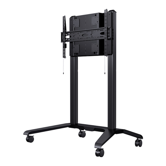
BT8565
UNIVERSAL EXTRA-LARGE
flat screen Display Trolley
WITH ADJUSTABLE HEIGHT
INSTALLATION GUIDE
SPECIFICATIONS
• Recommended for screens up to 120"
• Suitable for loads: 50kg - 83kg (110lbs - 183lbs)
• Suitable for displays with VESA
fixings up to 1000 x 600mm
• Tool-less height adjustment of screen
• Non-marking locking / braked castors included
• Integrated cable management
• Dimensions: H.1905mm W.1697mm D.991mm
®
& non-VESA
www.btechavmounts.com
vesa
1000
83kg
x
600
Advertisement

Related Manuals for B-Tech BT8565


Summary of Contents for B-Tech BT8565
-
Page 1: Installation Guide
BT8565 UNIVERSAL EXTRA-LARGE flat screen Display Trolley WITH ADJUSTABLE HEIGHT INSTALLATION GUIDE SPECIFICATIONS • Recommended for screens up to 120" • Suitable for loads: 50kg - 83kg (110lbs - 183lbs) ® • Suitable for displays with VESA & non-VESA fixings up to 1000 x 600mm •... -
Page 2: Table Of Contents
Please check carefully to make sure there are no missing or defective parts - defective parts must never be used. B-Tech AV Mounts, its distributors and dealers are not liable or responsible for damage or injury caused by improper installation, improper use or failure to observe these safety instructions. In such cases, all guarantees will expire. -
Page 4: Parts List
BT8565 PARTS LIST PLEASE KEEP THIS FOR FUTURE REFERENCE... - Page 5 PART NAME LEFT BASE RIGHT BASE BASE CONNECTOR PLATE CASTOR COLUMN MOUNTING BAR FRONT COVER BALANCE BOX COVER BALANCE BOX ADAPTOR PLATES MOUNTING PLATE INTERFACE ARM TRIM COLUMN REAR COVER COLUMN END CAP COLUMN STRIP M10 x 25mm CSK SCREW M8 x 35mm CSK SCREW M8 x 16mm CSK SCREW SLIDING NUT...
-
Page 6: Installation Instructions
INSTALLATION INSTRUCTIONS ASSEMBLE BASE Connect item 1 and item 2 together. Fix in place with item 3 by screwing 4 x item 17 into item 1 and 4 x item 17 into item 2 FIX CASTORS TO BASE Screw 4 x item 4 into items 1 & 2 and apply the brakes. - Page 7 ATTACH COLUMNS TO BASE Stand the base in its upright position. Insert item 5 into item 1 and screw 4 x item 18 through the underside of item 1. Insert item 5 into item 2 and screw 4 x item 18 through the underside of item 2.
- Page 8 ATTACH MOUNTING BARS TO COLUMNS Slide 4 x item 20 into the front outside slots of both item 5. Screw 4 x item 21 through holes in each of item 6 into item 20. Mount 1 x item 6 approx 10mm from the top of item 5 and the other item 6, 435mm down.
- Page 9 FIX ON FRONT COVERS Fix items 7 onto items 6 using 8 x item 22. INSERT BALANCE BOX MOUNTING SCREWS Insert 2 x item 23 into the top mounting bar (item 6) as shown. Do not fully tighten, leave a 10mm gap (approx).
- Page 10 INSERT BALANCE BOX REAR COVER Insert item 8 into the slots on the left and right side of item 9. TOP VIEW SLOT Rear of item 9 SLOT HOOK ON BALANCE BOX Hook on item 9 onto both of item 23 using the key holes on the rear of item 9. KEYHOLE...
- Page 11 LEVEL BALANCE BOX Using a crosshead screwdriver and a spirit level, adjust the levelling screws on the front of item 9 until the balance box is level. LEVELLING SCREW LEVEL (not included) FIX BALANCE BOX Fix item 9 to the bottom item 6 using item 24. Insert item 24 through these holes .
- Page 12 FIX ADAPTOR PLATES Fix 2 x item 10 onto item 9 using 4 x item 22. FIX MOUNTING PLATE Fix item 11 onto item 10 using items 22 & 25. There are 3 height options for mounting item 11. Use holes as shown below. Option 1 Option 2 Option 3...
- Page 13 FIX INTERFACE ARMS TO SCREEN Fix items 12 to the back of the screen using the interface kit (items A-N). Note: Ensure items 12 are positioned the correct way round. Spacers (items J-M) are to be used for screens with recessed fixings.
- Page 14 SCREEN ADJUSTMENT Level screen with the height adjustment screws at the top of item 12. HEIGHT LEVEL ADJUSTMENT SCREW Note: If necessary, laterally adjust SCREEN screen by hand. LOCK SCREEN TO MOUNTING PLATE (OPTIONAL) Secure screen onto item 11 using the locking screws at the bottom of item 12.
- Page 15 BALANCE SCREEN TO ENABLE HEIGHT ADJUSTMENT To balance the screen, use a drill driver at low torque setting and a 10mm socket. i. Turn the left spring tension point counter-clockwise for 5 seconds. ii. Turn the right spring tension point counter-clockwise for 5 seconds. iii.
- Page 16 ATTACH PLASTIC COVERS i. Attach item 14 to the rear of item 5. ii. Fit item 15 to the top of of item 5. iii. Fit item 13 into the front and rear of item 3. SCREEN INSERT COLUMN STRIPS Insert item 16 into the front slots on item 5.
- Page 17 CABLE MANAGEMENT Route cables through bottom of items 1 & 2. Cut-outs in item 1 & 2 can be used for cable management. Important: Allow enough slack in the cable to accommodate the height adjustment of the screen. Cables can be routed through the cut-outs in item 14.
-
Page 18: Product Dimensions
PLEASE KEEP THIS FOR FUTURE REFERENCE 12.5mm FRONT VIEW Max 1000mm 8.5mm 49mm 122mm HEIGHT OPTIONS Maximum Height Minimum Height THESE INSTRUCTIONS ARE INTENDED AS A GUIDE ONLY AND B-TECH ACCEPTS NO LIABILITY FOR THE ACCURACY OF THE INFORMATION CONTAINED IN THIS DOCUMENT. - Page 19 PLEASE KEEP THIS FOR FUTURE REFERENCE BACK VIEW SIDE VIEW 246.4mm 1070mm 136.5mm 35mm 30mm 111mm 609.9mm 270.1mm TOP VIEW 1697.1mm THESE INSTRUCTIONS ARE INTENDED AS A GUIDE ONLY AND B-TECH ACCEPTS NO LIABILITY FOR THE ACCURACY OF THE INFORMATION CONTAINED IN THIS DOCUMENT.
-
Page 20: B-Tech Contact Details
©2019 B-Tech International Design & Manufacturing Ltd. All rights reserved. B-Tech AV Mounts is a division of B-Tech International Design & Manufacturing Ltd. B-Tech AV Mounts and the B-Tech logo are registered trade marks. All other brands and product names are trademarks of their respective owners.
Need help?
Do you have a question about the BT8565 and is the answer not in the manual?
Questions and answers