Advertisement
Quick Links
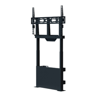
BT8569
Motorised Height Adjustable
FLOOR-TO-WALL STAND
INSTALLATION GUIDE
SPECIFICATIONS
• Recommended for screens from 55" - 86" (140cm - 218cm)
• Max load: 100kg (220lbs)
• Suitable for displays with VESA® & non-VESA fixings
up to 1000 x 600mm
• Motorised height adjustment range: 650mm (25.59")
• Features easy to use control panel and automatic
safety stop function
• Includes front cover and cable management for a
neat & tidy installation
• Stand dimensions:
H.1220mm - 1870mm x W.1070mm x D.256.5 - 272mm
(H.48" - 73.62" x W.42.13" x D.10.10" - 10.71")
www.btechavmounts.com
6
Advertisement

Related Manuals for B-Tech BT8569


Summary of Contents for B-Tech BT8569
- Page 1 BT8569 Motorised Height Adjustable FLOOR-TO-WALL STAND INSTALLATION GUIDE SPECIFICATIONS • Recommended for screens from 55" - 86" (140cm - 218cm) • Max load: 100kg (220lbs) • Suitable for displays with VESA® & non-VESA fixings up to 1000 x 600mm • Motorised height adjustment range: 650mm (25.59") •...
- Page 2 Please check carefully to make sure there are no missing or defective parts - defective parts must never be used. B-Tech AV Mounts, its distributors and dealers are not liable or responsible for damage or injury caused by improper installation, improper use or failure to observe these safety instructions.
- Page 4 BT8569 PARTS LIST PLEASE KEEP THIS FOR FUTURE REFERENCE BOX 3 SCREEN INTERFACE & COVER BOX 1 FLOOR-TO-WALL FIXING KIT BOX 2 COLUMNS...
- Page 8 ATTACH WALL PLATES TO COLUMNS Using items 4 & 5, fix 4x item 2 to items 10 & 11 (2 on each column). Use the slots on item 2 to position the stand the desired distance from the wall. Note: Item 2 can be reversed to allow the stand to be mounted further M8 x 14mm away or closer to the wall.
- Page 9 FIX STAND TO WALL i. Mark and drill 8 fixing holes in wall and insert item 6 into the holes. ii. Fix item 2 to wall using items 5 & 7. M8 x 63mm No.10 x 50mm COACH SCREW WASHER WALL PLUG WALL 10mm (13/32") Masonry...
- Page 10 CONNECT ALL CABLES i. Connect items 10, 11, 13 & 15/16/17 to item 12. ii. Mount item 14 onto item 20. Note: Use item 13 to extend the lifting column power cable. ATTACH CABLE MANAGEMENT TRAY Fix item 19 to item 18 using item 23. Note: Arrange cables on the underside of item 18 and use item 19 to hold cables in place.
- Page 11 ATTACH FRONT COVER Remove the liner off the 6 sticky tabs on item 22 and stick the cover firmly onto items 10 & 11. STICKY TAB ATTACH INTERFACE ARMS TO SCREEN Attach item 21 to the rear of the screen using the interface kit provided. Note: Ensure items 21 are positioned the correct way round and the same holes are used on both arms.
- Page 13 OPTIONAL SCREEN LEVELLING HEIGHT: Level the screen using the height adjustment screws on top of item 21. DEPTH: Use the adjustment screws at the rear of item 18 to push out the bottom of the screen to level. WARNING! Do not over tighten and damage screen. HEIGHT ADJUSTMENT SCREW...
-
Page 14: Cable Management
OPTIONAL ATTACH EXTENSION LEAD Use the cable ties (item 30) to fix an extension lead (not supplied) to item 18. Note: Refer to Operating Control System on page 15 for instructions on raising the screen. 3-GANG EXTENSION Note: Insert item 30 LEAD through the holes (not supplied) - Page 19 PLEASE KEEP THIS FOR FUTURE REFERENCE 35mm BACK SIDE VIEW VIEW 104mm 620mm 14mm 596mm FLOOR PLATE VIEW 135mm 108mm THESE INSTRUCTIONS ARE INTENDED AS A GUIDE ONLY AND B-TECH ACCEPTS NO LIABILITY FOR THE ACCURACY OF THE INFORMATION CONTAINED IN THIS DOCUMENT.
- Page 20 ©2022 B-Tech International Design and Manufacturing Ltd. All rights reserved. B-Tech AV Mounts is a division of B-Tech International Design and Manufacturing Ltd. B-Tech AV Mounts and the B-Tech logo are registered trade marks. All other brands and product names are trademarks of their respective owners.
Need help?
Do you have a question about the BT8569 and is the answer not in the manual?
Questions and answers