Crestron DigitalMedia 3 Series Do Manual
Hide thumbs
Also See for DigitalMedia 3 Series:
- User manual (2 pages) ,
- Quick start manual (7 pages) ,
- Supplemental manual (18 pages)
Table of Contents
Advertisement
Quick Links
DO
GUIDE
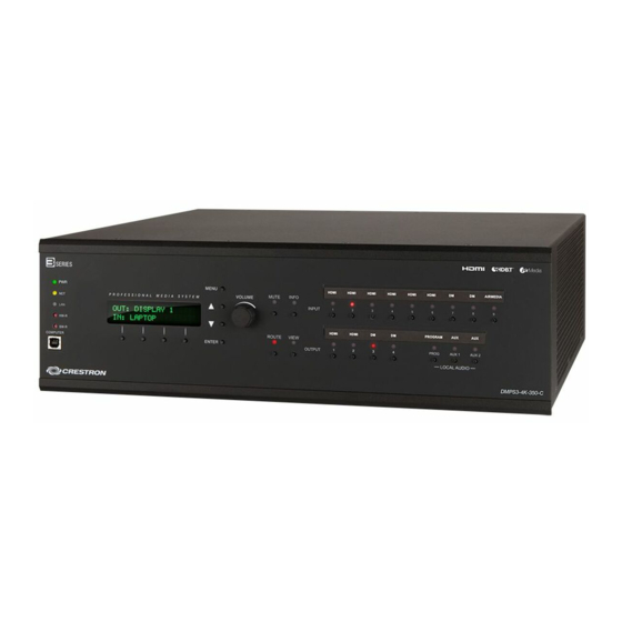
DMPS3-300-C-AEC/DMPS3-300-C/DMPS3-200-C
3-Series
DigitalMedia
Presentation System 300/200
®
TM
DO
Install the Device
The DMPS3-300-C-AEC, DMPS3-300-C, and DMPS3-200-C can be mounted into a rack or
placed onto a flat surface.
Mounting into a Rack
The DMPS3-300-C-AEC, DMPS3-300-C, and DMPS3-200-C occupy 2U of rack space. Using
a #1 or #2 Phillips screwdriver, attach the two included rack ears to the device. Then, mount the
device into the rack using four mounting screws (not included).
Rack Mounting
Placing onto a Flat Surface
When placing the device onto a flat surface or stacking it with
other equipment, attach the included feet near the corners on the
underside of the device.
NOTE:
No more than two DMPS3-300-C-AEC, DMPS3-300-C, or
DMPS3-200-C devices should be stacked.
DO
Check the Box
QTY PRODUCT
1
Connector, Plug, 3-Pin, Socket, Single Row
4
Connector, Plug, 4-Pin, Socket, Single Row
2
Connector, Plug, 8-Pin, Socket, Single Row
3
Connector, Plug, 2-Pin, Socket, Single Row
1
Cable Assembly, USB 2.0, Series "A" to "B" Plugs, 6'
2
Metal Bracket, Rack Mount, Ear, Aluminum
4
Feet, 0.5" Square, 0.23" High, Tapered, Adhesive
6
Screw, 06-32, 5/16" Long, Steel, Flat, Phillister, Undercut
1
Cable Assembly, Power Cord, 3 Prong, PVC Jacket, 6'7" Long
Supplied with the DMPS3-200-C Only
13
Connector, Plug, 5-Pin, Socket, Single Row
Supplied with the DMPS3-300-C-AEC and DMPS3-300-C Only
15
Connector, Plug, 5-Pin, Socket, Single Row
DO
Connect the Device
Check the website for details on input and output connections. Use Crestron
CAUTION:
To reduce the risk of fire, use only No. 26 AWG or larger telecommunication line cord for connection to the
PHONE interface connector.
Connections to the DMPS3-300-C-AEC and DMPS3-300-C
MC/LN 1 - 6:
From Balanced
INPUT:
Microphone/Line
IR-SERIAL OUT:
From Device
Audio Inputs
To IRP2 IR Emitter Probe
Outputs Contact or
From Microphone or
or One-Way Serial
Relay Closures (24
Line-Level Sources
Controlled Devices
Volts Max) Serial
Controlled Devices
AUD IN 1 - 5:
RELAY:
IR-IN:
From Video and
Output to
From
RGB Sources or
Controllable
CNXRMIRD
Codec Output
Devices
IR Receiver
L
R L
R
L
R L
R L
R
HDMI
®
INPUT 1 - 5:
RGB 3 - 5:
From Digital
Input From Analog
Video/Audio Sources
RGB/Video Sources
power supplies for Crestron equipment.
®
PHONE:
DMPS3-300-C-AEC
NET:
Model Only
To/From Any
USB-HID:
Cresnet
®
Device
For Future
Use
SPEAKER OUTPUTS:
COM A and COM B:
To 4W/8W Stereo
Bi-Directional RS-232 with
Speakers, or 70/100
Hardware and Software
Volt
Handshaking and
Mono Speakers
Modem Control
INPUT 5:
DM INPUT 6, 7:
From SPDIF,
From 8G+
Component,
DM
Transmitter
®
S-Video, or
HDMI OUTPUT 1, 2:
Composite Sources
To Digital Video/
RGB/Video Sources
Audio Devices
COLOR
PART NUM.
2003575
2003576
2003580
2012361
Black
2014966
Black
2033588
Black
2002389
Black
2007223
2001134
2003577
2003577
PROG OUT:
Program Audio Output
To Amplifier or
Amplified Speakers
GROUND
PoDM:
48 VDC Input
AUX OUT 1, 2:
POWER:
From Power
To VTC or Audio Mixer
From Line
Pack
or Codec Output
Voltage
PoDM
L
R L
R L
R
LAN:
DM OUTPUT 3, 4:
10/100/1000 BASE-T
To DM 8G+
Input
®
Ethernet to LAN
of DM
Receiver/Room
Controller
RGB/Video Sources
Advertisement
Table of Contents

Related Manuals for Crestron DigitalMedia 3 Series


Summary of Contents for Crestron DigitalMedia 3 Series
- Page 1 Supplied with the DMPS3-300-C-AEC and DMPS3-300-C Only Connector, Plug, 5-Pin, Socket, Single Row 2003577 Connect the Device Check the website for details on input and output connections. Use Crestron power supplies for Crestron equipment. ® CAUTION: To reduce the risk of fire, use only No. 26 AWG or larger telecommunication line cord for connection to the PHONE interface connector.
- Page 2 The Ringer Equivalence Number (REN) is an indication of the maximum number of devices allowed to be of Crestron Electronics, Inc. in the United States and/or other countries. HDMI and the HDMI logo are either trademarks or • Consult the dealer or an experienced radio/TV technician for help connected to a telephone interface.
Need help?
Do you have a question about the DigitalMedia 3 Series and is the answer not in the manual?
Questions and answers