Table of Contents
Advertisement
Quick Links
Advertisement
Table of Contents

Related Manuals for Crestron MPS-200


Summary of Contents for Crestron MPS-200
- Page 1 Crestron MPS-200 Multimedia Presentation System 200 Operations Guide...
- Page 2 • The apparatus must be installed in a way that the power cord The MPS-200 can be used with Class 2 output wiring. can be removed either from the wall outlet or from the device itself in order to disconnect the mains power.
-
Page 3: Table Of Contents
Crestron MPS-200 Multimedia Presentation System 200 Contents Multimedia Presentation System 200: MPS-200 Introduction ..........................1 Features and Functions ....................1 Applications......................... 4 Internal Block Diagram ....................5 Specifications ......................6 Physical Description....................10 Industry Compliance ....................20 Setup ............................21 Network Wiring...................... -
Page 5: Multimedia Presentation System 200: Mps-200
System Switcher The MPS-200 provides switching of four video and four RGB computer sources to a single projector or plasma display. Composite, S-video, component and RGBHV signals can be routed to the appropriate inputs on the display device, with control of the display provided via Ethernet, RS-232 or IR. - Page 6 Touchpanel Output A second discrete output is provided on the MPS-200 to feed a preview signal to the system touchpanel or other monitor. This output is controlled separately from the main display output, allowing a different source to be viewed. The touchpanel output provides a choice of QuickMedia™...
- Page 7 Multimedia Presentation System 200 Front Panel Control Out of the box, the MPS-200 front panel supports easy pushbutton routing of input sources to each of the outputs, and audio volume adjustment using the volume control knob. Dedicated buttons and indicators are also provided for separate control of system power and projector power.
-
Page 8: Applications
Multimedia Presentation System 200 Crestron MPS-200 Applications The following diagram shows an MPS-200 in a lecture hall application. MPS-200 in a Lecture Hall Application For more information on this and other QM applications, refer to the latest revision of the Crestron MediaManager Applications Guide (Doc. 6244), which is available from the Crestron website (http://www.crestron.com/manuals). -
Page 9: Internal Block Diagram
The signal type routed to OUT 1 is the same as the input signal type. For example, an S-video input signal will appear on the S-video output terminals when the signal is routed to OUT 1. The MPS-200 does not convert input signal formats. Multimedia Presentation System 200: MPS-200 • 5... -
Page 10: Specifications
Section with Line Level Out Vol/EQ Local Mic Gating With Phantom Power Local Mic Gating With Phantom Power Specifications Specifications for the MPS-200 are listed in the following table. MPS-200 Specifications SPECIFICATION DETAILS Processor ® 32-bit Freescale ColdFire Microprocessor Memory SDRAM... - Page 11 0.1 to 3.0 octaves, 0.1 octave steps PEQ Filter Center Frequency 25Hz to 20kHz, 0.5Hz steps PEQ Filter Types Low Pass, High Pass, Peaking Eq, Notch, Treble Shelf, Bass Shelf (Continued on following page) Multimedia Presentation System 200: MPS-200 • 7 Operations Guide – DOC. 6528B...
- Page 12 2.5 Amps @ 100-240 Volts AC, 50/60 Hz Available Cresnet Power 30 Watts Environmental Temperature 41° to 104°F (5° to 40°C) Humidity 10% to 90% RH (non-condensing) (Continued on following page) 8 • Multimedia Presentation System 200: MPS-200 Operations Guide – DOC. 6528B...
- Page 13 InfiNET Dimmer and Switch CLW-SW1RF CNSP-XX Custom Serial Interface Cable CNX-B12 12-Button Designer Keypad CNXRMIRD IR Receiver IRP2 IR Probe QM-AMP3X80MM 3-Channel Multimedia Amplifier QM-AMP3X80SR 3-Channel Sound Reinforcement Amplifier Multimedia Presentation System 200: MPS-200 • 9 Operations Guide – DOC. 6528B...
-
Page 14: Physical Description
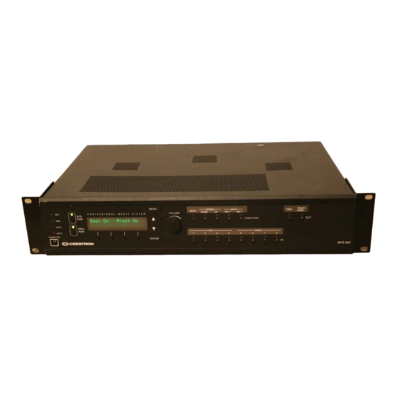
Multimedia Presentation System 200 Crestron MPS-200 Physical Description This section provides information on the connections, controls and indicators available on your MPS-200. MPS-200 Physical View (Front) MPS-200 Physical View (Rear) 10 • Multimedia Presentation System 200: MPS-200 Operations Guide – DOC. 6528B... - Page 15 Crestron MPS-200 Multimedia Presentation System 200 MPS-200 Overall Dimensions 12.54 in (31.86 cm) 11.47 in (29.13 cm) 17.03 in (43.24 cm) 3.47 in (8.81 cm) Multimedia Presentation System 200: MPS-200 • 11 Operations Guide – DOC. 6528B...
- Page 16 Multimedia Presentation System 200 Crestron MPS-200 MPS-200 Buttons and Ports 13 14 19 21 12 • Multimedia Presentation System 200: MPS-200 Operations Guide – DOC. 6528B...
- Page 17 Balanced/unbalanced stereo line-level inputs; Input Impedance: 24k ohms balanced/unbalanced; Balanced Input Level: -20 to +12 dBV; maximum; Unbalanced Input Level: -20 to +6 dBV; maximum (Continued on following page) Multimedia Presentation System 200: MPS-200 • 13 Operations Guide – DOC. 6528B...
- Page 18 (1) 3-pin 3.5mm detachable terminal block; Balanced/unbalanced mono line-level output; Output Impedance: 200 ohms balanced, 100 ohms unbalanced; Maximum Output Level: 4 V balanced, unbalanced (Continued on following page) 14 • Multimedia Presentation System 200: MPS-200 Operations Guide – DOC. 6528B...
- Page 19 (4) 2-pin 3.5mm detachable terminal blocks, IR/Serial output ports; IR output up to 1.2 MHz; One-way serial TTL/RS-232 (0-5 Volts) up to 9600 baud (Continued on following page) Multimedia Presentation System 200: MPS-200 • 15 Operations Guide – DOC. 6528B...
- Page 20 Rated for 0-24 Volts DC, referenced to GND; Input Impedance: 2.2k ohms pulled up to 5 Volts DC; Logic Threshold: 2.5 Volts DC nominal with 1 Volt hysteresis band (Continued on following page) 16 • Multimedia Presentation System 200: MPS-200 Operations Guide – DOC. 6528B...
- Page 21 Ready Common (GND) Ground (DSR) Data Set MPS-200 Ready From (RTS) Request To MPS-200 Send (CTS) Clear To Send MPS-200 (RI) Ring Indicator MPS-200 (Continued on following page) Multimedia Presentation System 200: MPS-200 • 17 Operations Guide – DOC. 6528B...
- Page 22 DIP switches (#25) (1) 8-wire RJ-45 with two LED indicators; 10/100BaseT Ethernet port; Green LED indicates link status; Yellow LED indicates Ethernet activity (Continued on following page) 18 • Multimedia Presentation System 200: MPS-200 Operations Guide – DOC. 6528B...
- Page 23 Transmission levels on the infrared – serial output connectors are in the 0 to +5 VDC range, which may not be compatible with all RS-232 devices. This eight-pin RJ-45 port provides connectivity to a touchpanel with a CH input port or a Crestron device with a CAT5 video input. This port provides component, composite or S-video balanced output over CAT5 wiring.
-
Page 24: Industry Compliance
This product is Listed to applicable UL Standards and requirements by Underwriters Laboratories Inc. (E302724) As of the date of manufacture the MPS-200 has been tested and found to comply with specifications for CE marking and standards per EMC and Radiocommunications Compliance Labelling. -
Page 25: Setup
The MPS-200 also uses high-speed Ethernet for communications between the control system and a device, computer, digital media server and other IP-based devices. For information on connecting Ethernet devices in a Crestron system, refer to the latest version of the Crestron e-Control Reference Guide (Doc. -
Page 26: Quickmedia Wiring
(0.84-1.27 cm) when making a connection. The twists are critical to canceling out interference between the wires. The aggregate cable length of a signal path originating at the MPS-200 and terminating at a QM receiver must not exceed 450 feet (137 meters). Video signals may experience a loss of quality over very long lengths of cable. -
Page 27: Installation
The MPS-200 can be mounted in a rack or stacked with other equipment. Two “ears” are provided with the MPS-200 so that the unit can be rack mounted. These ears must be installed prior to mounting. Complete the following procedure to attach the ears to the unit. -
Page 28: Hardware Hookup
RGB Input Ports” on page 27. Stacking Four “feet” are located on the bottom of the MPS-200 so that if the unit is not rack mounted, the rubber feet can provide stability when the unit is placed on a flat surface or stacked. - Page 29 CAUTION: Do not bridge speaker outputs CAUTION: All source devices should be grounded to the MPS-200. NOTE: The MPS-200 can only be powered by the included power cord. Power cannot be supplied from network devices that are connected to the mini-terminal block connectors.
- Page 30 GND Typical Balanced/Unbalanced Inputs Unbalanced Input Balanced Input Shield Jumpers Left/Microphone Left/Microphone Shield Right/Line Right/Line Shield Typical Balanced/Unbalanced Outputs Balanced Output Unbalanced Output Shield Right Right Left Left 26 • Multimedia Presentation System 200: MPS-200 Operations Guide – DOC. 6528B...
-
Page 31: Configure The Rgb Input Ports
Each of the RGB input ports feature a set of six DIP switches located inside the MPS-200. These switches are used to set the sync input impedance of each port and simulate the presence of a monitor (DDC) for each RGB input. - Page 32 SYNC INPUT IMPEDANCE NOTE: The function table is also located on the bottom of the MPS-200. NOTE: The factory setting for the DIP switches are DDC disabled (switches 1 & 2 in the OFF position) and 1k ohm impedance (switches 3 through 6 in the OFF position).
- Page 33 Multimedia Presentation System 200 Label the Buttons Use Crestron Engraver software to print custom labels for the MPS-200’s front panel buttons and LEDS. Crestron recommends printing on 100-pound paper. Paper weighing less than 100 pounds will tend to crumple while sliding in, while paper weighing more than 100 pounds may not fit.
-
Page 34: Programming Software
Have a question or comment about Crestron software? Answers to frequently asked questions (FAQs) can be viewed in the Online Help section of the Crestron website. To post a question or view questions you have submitted to Crestron’s True Blue Support, log in at http://support.crestron.com. -
Page 35: Programming With Simpl Windows
SystemBuilder. Programming with SIMPL Windows NOTE: While SIMPL Windows can be used to program the MPS-200, it is recommended to use SystemBuilder for configuring an MPS-200 system. SIMPL Windows is Crestron’s premier software for programming Crestron control systems. -
Page 36: Switching Programs
View. A description for each signal in the symbol is described in the SIMPL Windows help file (F1). Switching Programs If a custom program is loaded into the MPS-200, the MPS-200 will run the custom program when it boots up. To switch to the out-of-the-box program: 1. Press and release HW-R. -
Page 37: Uploading And Upgrading
CRESTRON TOOLBOX VIA USB CABLE • The COMPUTER port on the MPS-200 connects to the USB port on the PC via the included Type-A to Type B USB cable. • Use the Address Book in Crestron Toolbox to create an entry using the expected communication protocol (USB). -
Page 38: Programs And Firmware
CRESTRON TOOLBOX • Establish USB communications between the MPS-200 and a PC. • Enter the IP address, IP mask and default router of the MPS-200 via the Crestron Toolbox (Functions | Ethernet Addressing); otherwise enable DHCP. • Confirm Ethernet connections between MPS-200 and PC. If connecting through a hub or router, use CAT5 straight through cables with 8-pin RJ-45 connectors. -
Page 39: Configuration & Operation
Multimedia Presentation System 200 Configuration & Operation The MPS-200 can be used for audio and video switching without any programming required. This is ideal for those that need a basic audio-video switching system. Prior to operation, the MPS-200 must be configured for use. - Page 40 No to return to the menu. NOTE: The following sections describe configuration instructions when the MPS-200 is running the out-of-the-box program or if an administrator password was entered (while a custom program is running). If a user password was entered while a custom program is running, the user can view the settings but cannot make changes.
- Page 41 • Network Setup: Contains controls for setting the IP address of the MPS-200, the IP address of the subnet mask used by the MPS-200, the IP address of the default router used by the MPS-200, the DHCP mode of the MPS-200, and the WINS mode of the MPS-200.
- Page 42 Adjust the Program Bass level with the j and k buttons. Press the k button to increase the bass level. Press the j button to lower the bass level. 38 • Multimedia Presentation System 200: MPS-200 Operations Guide – DOC. 6528B...
- Page 43 Access the Program Output menu as described on page 37. • Press the k or j buttons until “Min Volume” is displayed on the LCD and press ENTER to open the Program Minimum Volume controls. Multimedia Presentation System 200: MPS-200 • 39 Operations Guide – DOC. 6528B...
- Page 44 Press the k button to increase the Program Maximum Volume level. Press the j button to lower the Program Maximum Volume level. The lowest Program Maximum Volume setting is 50%. 40 • Multimedia Presentation System 200: MPS-200 Operations Guide – DOC. 6528B...
- Page 45 Program Startup Volume level. To adjust the Program Startup Volume level: • Access the Program Output menu as described on page 37. Multimedia Presentation System 200: MPS-200 • 41 Operations Guide – DOC. 6528B...
- Page 46 To set the SPEECH output’s source mix: • Access the Speech Output menu as described above. • Press the k or j buttons until “Source Mix” is displayed on the LCD and 42 • Multimedia Presentation System 200: MPS-200 Operations Guide – DOC. 6528B...
- Page 47 Adjust the Speech Bass level with the j and k buttons. Press the k button to increase the Speech Bass level. Press the j button to lower the Speech Bass level. Multimedia Presentation System 200: MPS-200 • 43 Operations Guide – DOC. 6528B...
- Page 48 Press the k or j buttons until “Speech Delay” is displayed on the LCD and press ENTER to open the Speech Delay controls. The current speech delay will be displayed. 44 • Multimedia Presentation System 200: MPS-200 Operations Guide – DOC. 6528B...
- Page 49 PROG OUT (and SPEAKER 20W 8Ω if the internal amplifier is used). ⇒ Speech Only: The front panel volume control will now only control the output volume for SPEECH OUT. Multimedia Presentation System 200: MPS-200 • 45 Operations Guide – DOC. 6528B...
- Page 50 Press ENTER to save changes and return to the Speech Output menu. To cancel without saving changes, press MENU. The MPS-200 ships with the Volume Control Mode set to the Master Vol. setting. When switching the Volume Control Mode from the Master Vol. setting to either the Program Only setting, the Speech Only setting, or the user selectable Pgm/Spch Sel.
- Page 51 Access the Speech Output menu as described on page 42. • Press the k or j buttons until “Max Volume” is displayed on the LCD and press ENTER to open the Speech Maximum Volume controls. Multimedia Presentation System 200: MPS-200 • 47 Operations Guide – DOC. 6528B...
- Page 52 Speech Startup Volume level. Press the j button to lower the Speech Startup Volume level. The highest Speech Startup Volume setting is 100%. 48 • Multimedia Presentation System 200: MPS-200 Operations Guide – DOC. 6528B...
- Page 53 • Access the Record Output menu as described above. • Press ENTER to open the Record Source Mix controls. Record Source Mix Controls Record Source Mix Aud. Only Multimedia Presentation System 200: MPS-200 • 49 Operations Guide – DOC. 6528B...
- Page 54 Variable: The RECORD output operates at a variable level. • Press ENTER to save changes and return to the previous screen. To cancel without saving changes, press MENU. 50 • Multimedia Presentation System 200: MPS-200 Operations Guide – DOC. 6528B...
- Page 55 Press MENU or ENTER to save changes and return to the previous screen. Input Compensation The compensation level of each input can be set from the MPS-200’s front panel. The line outputs are not affected by changes made to the input compensation level.
- Page 56 Access the Audio Setup menu as described on page 37. • Press the k or j buttons until “Master Startup Vol.” is displayed on the LCD and press ENTER to open the Master Startup Volume control. 52 • Multimedia Presentation System 200: MPS-200 Operations Guide – DOC. 6528B...
- Page 57 Press MENU or ENTER to save changes and return to the previous screen. Microphones The MPS-200 can be connected to two microphones that are channeled to the SPEECH outputs and can be incorporated into the RECORD and PROGRAM outputs. The microphone inputs feature switchable gating and can provide phantom power to microphones requiring phantom power.
- Page 58 The gain for each microphone input can be individually set. To adjust the gain of a microphone input: • Access the Microphone menu as described on page 53. 54 • Multimedia Presentation System 200: MPS-200 Operations Guide – DOC. 6528B...
- Page 59 To exit the Video Setup menu, press MENU. Name Video Inputs The MPS-200 ships with default names assigned to each of the inputs. Input 1 is called “BNC 1”. Input 2 is called “BNC 2”. Input 3 is called “BNC 3”. Input 4 is called “BNC 4”.
- Page 60 Select Input Type The four BNC video inputs of the MPS-200 can accept composite, S-video, or component signals. Specifying the input signal type determines which of the output connectors receives the selected input signal. To specify the signal types expected by each of the inputs: •...
- Page 61 After all inputs have been configured, press MENU to return to the Video Setup menu. Name Video Outputs The MPS-200 ships with default names assigned to each of the outputs. Output 1 is called “PROJECTOR”. Output 2 is called “TOUCHPANEL”. To change the output names: •...
- Page 62 After all outputs have been named, press MENU to return to the Video Setup menu. Network Setup The network settings of the MPS-200 can be configured and reviewed from the front panel using the Network Setup menu. NOTE: Some changes to network settings may require a reboot to take effect. The system will automatically reboot when necessary.
- Page 63 ENTER. To cancel the operation and return to the Network Setup menu, press MENU. Set the Subnet Mask The MPS-200 can be configured to use an IP Subnet Mask for TCP/IP communications. To set the address of the IP Subnet Mask: •...
- Page 64 (*). • To save the setting and return to the Network Setup menu, press ENTER. To cancel the operation and return to the Network Setup menu, press MENU. 60 • Multimedia Presentation System 200: MPS-200 Operations Guide – DOC. 6528B...
- Page 65 Crestron MPS-200 Multimedia Presentation System 200 Set the WINS Mode The MPS-200 can use a WINS server to obtain an IP address. To set the WINS mode: • Access the Network Setup menu as described on page 58. • Press the k or j buttons until “WINS” is displayed on the LCD and press ENTER button to display the WINS controls.
- Page 66 Domain name (if entered) will be displayed. Display the Domain Name Domain Name corporate.crestron. • Press ENTER to change the Domain name. A cursor is placed after the last character in the Domain name. 62 • Multimedia Presentation System 200: MPS-200 Operations Guide – DOC. 6528B...
- Page 67 ENTER. To cancel the operation and return to the Domain name display, press MENU. Set the RoomView Mode The MPS-200 can be configured to report to RoomView Express (formerly known as RoomView 6.0) or RoomView Server Edition (formerly known as RoomView 7.0). To set the version of RoomView: •...
- Page 68 MENU. Name the Function Buttons The MPS-200 ships with default names assigned to each of the five function buttons. Button 1 is called “MUTE”. Button 2 is called “SCREEN DOWN”. Button 3 is called “SCREEN UP”. Button 4 is called “LIGHTS PRESET 1”. Button 5 is called “LIGHTS PRESET 2”.
- Page 69 Press the k or j buttons until “Devices” is displayed on the LCD and press ENTER. • The MPS-200 will poll the Cresnet network to detect Cresnet devices. The display will prompt the user to press ENTER to ID all devices. Multimedia Presentation System 200: MPS-200 • 65...
- Page 70 Crestron Toolbox. Refer to the respective infiNET switch and dimmer manuals for more information. Upgrade Connected APADs APAD devices may need to be programmed to work with the MPS-200. If a connected APAD does not display controls for the MPS-200, perform the following. •...
- Page 71 To cancel the process without saving any changes, press MENU. The display will return to the Control Setup menu. View System Information Use the front panel to view information about the MPS-200. Information that can be viewed includes program information, hardware information, network information, and operating system information.
- Page 72 Multimedia Presentation System 200 Crestron MPS-200 NOTE: This information can be viewed using Crestron Toolbox. For more information, refer to the Crestron Toolbox help file. • Access the Control Setup menu as described on page 64. • Press the k or j buttons until “Info” is displayed on the LCD and press ENTER to display the Info menu.
- Page 73 To return to the Control Setup menu, press MENU. Review System Messages The MPS-200 stores system messages in a message log. The presence of new messages in the log is indicated when the MSG LED is lit. To review system messages using the front panel: •...
- Page 74 • Press MENU to return to the Control Setup menu. NOTE: The contents of the message log can be read and saved using Crestron Toolbox. For more information, refer to the Crestron Toolbox help file. Set the Date and Time Use the front panel to set the MPS-200’s date and time.
- Page 75 • To return to the Control Setup menu, press MENU. NOTE: The date and time can be set using Crestron Toolbox. For more information, refer to the Crestron Toolbox help file. Multimedia Presentation System 200: MPS-200 • 71...
- Page 76 Crestron MPS-200 Restore Default Settings The MPS-200 can be restored to its default factory settings from the front panel. Users can select to restore the audio settings or to restore the audio settings, source names, output names, and function names.
- Page 77 The MPS-200’s front panel controls can be locked to prevent operational changes from the buttons on the front of the MPS-200. While locked, the menu can be accessed by pressing the MENU button. To open the Front Panel Lock control: •...
-
Page 78: Operation
Press ENTER to save the new setting and return to the Control Setup menu. Operation Using the out-of-the-box functionality, the MPS-200 can be operated from the front panel, an APAD, a 12-button keypad such as the CNX-B12 or the C2N-DB12, or the C2N-FTB FlipTop Control Center. - Page 79 100% volume when SYS PWR is pressed. The volume level of the MPS-200 is adjusted with the volume control knob. The volume control knob will only control the volume parameter that was selected when the Volume Control Mode was specified as described on 45.
- Page 80 NOTE: This function will only work if a CLS-C6, infiNET switch, or infiNET dimmer was previously identified and connected to the MPS-200. The CLS-C6 can be identified as a Cresnet device in the MPS-200 setup screens as described on page 65. Crestron’s infiNET switches and dimmers require a C2N-MNETGW to be identified as described on page 65 in addition to identifying the individual switch and/or dimmer with a unique identity code (MNET ID) using Crestron Toolbox.
- Page 81 3, BNC 4, RGBHV 5, RGBHV 6, RGBHV 7, or RGBHV 8). NOTE: Typically, signal routing information is not displayed on the front panel of the MPS-200. However, if an output button on the MPS-200 was pressed at any point during operation, routing information will be displayed and updated should any changes to routing be made.
- Page 82 NOTE: This function will only work if a CLS-C6, infiNET switch, or infiNET dimmer was previously identified and connected to the MPS-200. The CLS-C6 can be identified as a Cresnet device in the MPS-200 setup screens as described on page 65. Crestron’s infiNET switches and dimmers require a C2N-MNETGW to be identified as described on page 65 in addition to identifying the individual switch and/or dimmer with a unique identity code (MNET ID) using Crestron Toolbox.
- Page 83 45. Mute Audio To mute the audio output, press the MUTE button. To unmute, press the MUTE button again. The front panel of the MPS-200 will indicate the status of the mute function. Control from a C2N-FTB The following describes operation of the system when using the out-of-the-box functionality and a C2N-FTB FlipTop Control Center.
- Page 84 To turn on the system, press any of the source buttons on the control center. NOTE: Typically, signal routing information is not displayed on the front panel of the MPS-200. However, if an output button on the MPS-200 was pressed at any point during operation, routing information will be displayed and updated should any changes to routing be made.
- Page 85 Multimedia Presentation System 200 Mute Audio To mute the audio output, press the MUTE button. To unmute, press the MUTE button again. The front panel of the MPS-200 will indicate the status of the mute function. Adjust Lighting To toggle between preset light settings, press either of the LIGHTS buttons. The front panel of the MPS-200 will indicate the selected preset light setting.
-
Page 86: Problem Solving
Multimedia Presentation System 200 Crestron MPS-200 Problem Solving Troubleshooting The following table provides corrective action for possible trouble situations. If further assistance is required, please contact a Crestron customer service representative. MPS-200 Troubleshooting TROUBLE POSSIBLE CAUSE(S) CORRECTIVE ACTION Unexpected Network devices are not... - Page 87 NOTE: If your PC does not have the USB driver installed, after connecting the MPS-200 to the PC using the USB cable, you will see a dialog box on your PC screen asking you to install the USB driver. For instructions on how to install the USB driver, refer to the Crestron Toolbox help file.
-
Page 88: Check Network Wiring
C2N-ANLZ, refer to the C2N-ANLZ Operations Guide (Doc. 6473). Battery Replacement A Lithium battery is used to power the system clock within the MPS-200. Under normal conditions, it will last for approximately 10 years. In the event that the clock fails, only an authorized technician should replace it. -
Page 89: Reference Documents
Cresnet power usage of the entire chain. If the unit is home-run from a Crestron system power supply network port, the Cresnet power usage of that unit is the Cresnet power usage of the entire run. The wire gauge and the Cresnet power usage of the run should be used in the following equation to calculate the cable length value on the equation’s left side. -
Page 90: Further Inquiries
For assistance in your local time zone, refer to the Crestron website (http://www.crestron.com/offices) for a listing of Crestron worldwide offices. You can also log onto the online help section of the Crestron website (http://www.crestron.com/onlinehelp) to ask questions about Crestron products. -
Page 91: Software License Agreement
This Agreement may only be modified by a writing signed by an authorized officer of Crestron. Updates may be licensed to You by Crestron with additional or different terms. This is the entire agreement between Crestron and You relating to the Software and it supersedes any prior representations, discussions, undertakings, communications or advertising relating to the Software. - Page 92 “applets” incorporated into the Software), the accompanying media and printed materials and any copies of the Software are owned by Crestron or its suppliers. The Software is protected by copyright laws and international treaty provisions. Therefore, you must treat the Software like any other copyrighted material, subject to the provisions of this Agreement.
-
Page 93: Return And Warranty Policies
Purchasers should inquire of the dealer regarding the nature and extent of the dealer's warranty, if any. CRESTRON shall not be liable to honor the terms of this warranty if the product has been used in any application other than that for which it was intended or if it has been subjected to misuse, accidental damage, modification or improper installation procedures. - Page 94 Crestron Electronics, Inc. Operations Guide – DOC. 6528B 15 Volvo Drive Rockleigh, NJ 07647 (2016140) 10.07 Tel: 888.CRESTRON Fax: 201.767.7576 Specifications subject to www.crestron.com change without notice.
Need help?
Do you have a question about the MPS-200 and is the answer not in the manual?
Questions and answers