Crestron 3-Series DigitalMedia 300 Operation Manual
Hide thumbs
Also See for 3-Series DigitalMedia 300:
- Supplemental manual (20 pages) ,
- Quick start manual (9 pages) ,
- Do manual (2 pages)

Subscribe to Our Youtube Channel
Related Manuals for Crestron 3-Series DigitalMedia 300


Summary of Contents for Crestron 3-Series DigitalMedia 300
- Page 1 Crestron DMPS3-300-C/DMPS3-200-C 3-Series DigitalMedia™ Presentation System 300 ® Operations Guide...
- Page 2 Important Safety Instructions • Read these instructions. WARNING: • Keep these instructions. TO REDUCE THE RISK OF FIRE OR ELECTRIC SHOCK, • Heed all warnings. DO NOT EXPOSE THIS APPARATUS TO RAIN OR • Follow all instructions. MOISTURE. THE APPARATUS SHALL NOT BE EXPOSED •...
- Page 3 Other trademarks, registered trademarks and trade names may be used in this document to refer to either the entities claiming the marks and names or their products. Crestron disclaims any proprietary interest in the marks and names of others. Crestron is not responsible for errors in typography or photography.
-
Page 5: Table Of Contents
Check Cresnet Network Wiring ................52 Reference Documents ....................53 Further Inquiries ......................53 Future Updates ......................54 Return and Warranty Policies ....................55 Merchandise Returns / Repair Service ..............55 Crestron Limited Warranty ..................55 Contents • i Operations Guide – DOC. 7591A... -
Page 7: 3-Series Digitalmedia Presentation System 300: Dmps3-300-C And Dmps3-200-C
3-Series DigitalMedia Presentation System 300: DMPS3-300-C and DMPS3-200-C Introduction ® The DMPS3-300-C and DMPS3-200-C systems from Crestron are complete, high-definition presentation control and signal routing solutions for classrooms, boardrooms, lecture halls, and videoconference rooms. Integrating the control system, multimedia matrix switcher, audio DSP, and amplifier all into one 3-space rack mount package, the systems afford extensive signal routing flexibility and high-performance signal processing without the need for separate components. - Page 8 1. For DM 8G+ wiring, use Crestron DM-CBL-8G DigitalMedia 8G™ cable, Crestron DM-CBL DigitalMedia cable, Crestron DM-CBL-D DigitalMedia D cable, or generic CAT5e (or better) UTP or STP. Maximum wire length for DM 8G+ is 330 ft (100 m) between devices. Shielded cable and connectors are recommended to safeguard against unpredictable environmental electrical noise, which may impact performance at resolutions above 1080p.
- Page 9 2. HDMI requires an appropriate adapter or interface cable to accommodate a DVI or DisplayPort Multimode signal. CBL-HD-DVI interface cables available separately. 3. For DM 8G+ wiring up to 330 ft (100 m) between devices, use Crestron DM-CBL-8G DigitalMedia 8G cable, Crestron DM-CBL DigitalMedia cable, Crestron DM-CBL-D DigitalMedia D cable, or generic CAT5e (or better) UTP or STP.
- Page 10 (40 watts mono @ 70 or 100 volts). Fed by the main program output, the internal amplifier benefits fully from the onboard DSP. For larger applications, Crestron AMP-series power amplifiers may be added, providing a complete solution for driving separate program and speech speakers, or any multizone speaker system.
- Page 11 DMPS3-300/200-C can also extend Ethernet out to each display and source device, providing high-speed connectivity for each room device that requires a LAN connection. Ethernet is also utilized internally by the Crestron control bus to manage each transmitter and receiver and provide device control.
- Page 12 CEC Embedded Device Control The primary objective of every Crestron system is to enable precisely the control desired for a seamless user experience. In addition to conventional IR, RS-232, and Ethernet device control, the DMPS3-300/200-C can provide an alternative by harnessing the CEC (Consumer Electronics Control) signal embedded in HDMI.
- Page 13 Crestron DMPS3-300-C/DMPS3-200-C 3-Series DigitalMedia Presentation System 300 Applications The following diagram shows a DMPS3-300-C in a presentation room application. DMPS3-300-C in a Presentation Room Application 3-Series DigitalMedia Presentation System 300: DMPS3-300/200-C • 7 Operations Guide – DOC. 7591A...
- Page 14 3-Series DigitalMedia Presentation System 300 Crestron DMPS3-300-C/DMPS3-200-C The following diagram shows a DMPS3-300-C in a video conferencing application. DMPS3-300-C in a Video Conferencing Application 8 • 3-Series DigitalMedia Presentation Systems: DMPS3-300/200-C Operations Guide – DOC. 7591A...
- Page 15 Crestron DMPS3-300-C/DMPS3-200-C 3-Series DigitalMedia Presentation System 300 The following diagram shows the audio controls in the microphone input stage. Labels M1 through M6 correspond to the labels in the mixer stage portion of the Audio Flow Diagram below. DMPS3-300-C Mic Audio Controls Diagram The following audio flow diagram shows the audio controls in the DMPS3-300-C mixer stage.
-
Page 16: Internal Block Diagrams
3-Series DigitalMedia Presentation System 300 Crestron DMPS3-300-C/DMPS3-200-C Internal Block Diagrams The following diagrams represent the audio and video switching functions and signal flow of the DMPS3-300-C. DMPS3-300-C Audio Block Diagram 10 • 3-Series DigitalMedia Presentation Systems: DMPS3-300/200-C Operations Guide – DOC. 7591A... -
Page 17: Specifications
Crestron DMPS3-300-C/DMPS3-200-C 3-Series DigitalMedia Presentation System 300 DMPS3-300-C Video Block Diagram Specifications Specifications for the DMPS3-300/200-C are listed in the following table. DMPS3-300/200-C Specifications SPECIFICATION DETAILS Operating System Crestron 3-Series; Real time, preemptive, multithreaded/multitasking kernel; Transaction-Safe Extended FAT file system;... - Page 18 DHCP, Private Network Mode, SSL, IEEE 802.1X, SNMP, BACnet™/IP, IPv4 or IPv6, active directory authentification, RSTP, SMTP e-mail client, IIS v.6.0 web server; Installer setup via Crestron Toolbox or MSIE ® Cresnet Cresnet master mode DigitalMedia DM 8G+, HDCP, EDID, CEC, PoDM, HDBaseT...
- Page 19 Crestron DMPS3-300-C/DMPS3-200-C 3-Series DigitalMedia Presentation System 300 DMPS3-300/200-C Specifications (Continued) SPECIFICATION DETAILS Video (Continued) 640 x 480 @ 60 Hz Input Resolutions 720 x 480 @ 60 Hz (480p) HDMI and HDBaseT, 720 x 576 @ 50 Hz (576p) Progressive...
- Page 20 3-Series DigitalMedia Presentation System 300 Crestron DMPS3-300-C/DMPS3-200-C DMPS3-300/200-C Specifications (Continued) SPECIFICATION DETAILS Video Input Resolutions 1400 x 1050 @ 60 H RGB (Continued) 1440 x 900 @ 60 Hz 1600 x 1200 @ 60 Hz 1680 x 1050 @ 60 Hz...
- Page 21 Crestron DMPS3-300-C/DMPS3-200-C 3-Series DigitalMedia Presentation System 300 DMPS3-300/200-C Specifications (Continued) SPECIFICATION DETAILS Audio independent 4-channel mic plus source mixer Switcher/Mixer per output, independent stereo DSP per (DMPS3-200-C) (Continued) analog output, integrated power amplifier, digital audio pass-through mode Typical of Microphone Input...
- Page 22 3-Series DigitalMedia Presentation System 300 Crestron DMPS3-300-C/DMPS3-200-C DMPS3-300/200-C Specifications (Continued) SPECIFICATION DETAILS Audio Typical of Analog Line Outputs with DSP (Continued) Digital-To-Analog 24-bit 48 kHz Conversion Mics (Level Adjustment -80.0 to +10 dB, plus mute and pan Range Per Mic Input) Mics Master -80.0 to +10 dB level adjustment range, plus...
- Page 23 Crestron DMPS3-300-C/DMPS3-200-C 3-Series DigitalMedia Presentation System 300 DMPS3-300/200-C Specifications (Continued) SPECIFICATION DETAILS Audio Typical of HDMI and DM Outputs (Continued) Output Signal Types HDMI (Outputs 1 and 2), (DMPS3-200-C) DM 8G+/HDBaseT (Outputs 3 and 4) Formats Dolby Digital, Dolby Digital EX, DTS,...
- Page 24 16.4 lb (7.5 kg) DMPS3-200-C 16.4 lb (7.5 kg) Available Accessories AMP-Series Commercial Amplifiers AM-100 AirMedia™ Presentation Gateway CBL Series Crestron Certified Interface Cables CNSP-XX Custom Serial Interface Cable CNXRMIRD IR Receiver CRESNET Cresnet Control Cable ® ® Crestron App Control App for Apple ®...
- Page 25 Crestron DMPS3-300-C/DMPS3-200-C 3-Series DigitalMedia Presentation System 300 DMPS3-300/200-C Specifications (Continued) SPECIFICATION DETAILS Available Accessories (Continued) DM-RMC-100-C DigitalMedia 8G+ Receiver and Room Controller DM-RMC-200-C DigitalMedia 8G+ Receiver and Room Controller 200 with Scaler and Power Amplifier DM-RMC-SCALER-C DigitalMedia 8G+ Receiver and Room Controller with Scaler 4K DigitalMedia 8G+™...
-
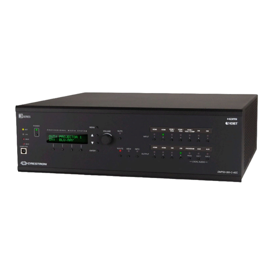
Page 26: Physical Description
3-Series DigitalMedia Presentation System 300 Crestron DMPS3-300-C/DMPS3-200-C Physical Description This section provides information on the connections, controls, and indicators available on the DMPS3-300/200-C. DMPS3-300-C Physical View DMPS3-300/200-C Overall Dimensions (Side View) 20 • 3-Series DigitalMedia Presentation Systems: DMPS3-300/200-C Operations Guide – DOC. 7591A... - Page 27 Crestron DMPS3-300-C/DMPS3-200-C 3-Series DigitalMedia Presentation System 300 DMPS3-200-C Dimensions (Front View) DMPS3-200-C (Rear View) DMPS3-300-C Dimensions (Front View) 3-Series DigitalMedia Presentation System 300: DMPS3-300/200-C • 21 Operations Guide – DOC. 7591A...
- Page 28 3-Series DigitalMedia Presentation System 300 Crestron DMPS3-300-C/DMPS3-200-C DMPS3-300-C (Rear View) NOTE: In the following table, the reference designation and quantity of several of the connectors and indicators vary between the DMPS3-300/200-C models. Refer to the previous illustrations and the description in the table for clarification.
- Page 29 Crestron DMPS3-300-C/DMPS3-200-C 3-Series DigitalMedia Presentation System 300 Connectors, Controls, and Indicators (Continued) CONNECTORS, DESCRIPTION CONTROLS, AND INDICATORS (1) Push button and red LED, mutes the program MUTE audio output (1) Push button and red LED, selects Route ROUTE mode to allow routing changes...
- Page 30 3-Series DigitalMedia Presentation System 300 Crestron DMPS3-300-C/DMPS3-200-C Connectors, Controls, and Indicators (Continued) CONNECTORS, DESCRIPTION CONTROLS, AND INDICATORS INPUT (1) 5-pin 3.5 mm detachable terminal block; Comprises (4) programmable digital inputs; 1 2 3 4 G Input voltage range: 0 to 24 volts dc, referenced to GND;...
- Page 31 Crestron DMPS3-300-C/DMPS3-200-C 3-Series DigitalMedia Presentation System 300 Connectors, Controls, and Indicators (Continued) CONNECTORS, DESCRIPTION CONTROLS, AND INDICATORS (4) 4-pin 3.5 mm detachable terminal blocks; Cresnet Master ports, paralleled; 24 Y Z G Available Cresnet power: 30 watts 24: Power (24 volts dc)
- Page 32 3-Series DigitalMedia Presentation System 300 Crestron DMPS3-300-C/DMPS3-200-C Connectors, Controls, and Indicators (Continued) CONNECTORS, DESCRIPTION CONTROLS, AND INDICATORS 100-240 V – 4.0 A (1) IEC 60320 C14, main power inlet; 50/60 Hz Mates with removable power cord, included AUX OUT (2) 5-pin 3.5 mm detachable terminal blocks;...
- Page 33 DM; Connects to DM 8G+ input of a DM receiver/room controller or other DM device via CAT5e or Crestron DM-CBL-8G cable; (2) LEDs, green LEDs indicate DM link status, amber LEDs indicate video and HDCP signal presence, for each respective port...
- Page 34 7. Supplying Power over DM (PoDM) requires external power pack, sold separately. 8. For DM 8G+ wiring up to 330 ft (100 m) between devices, use Crestron DM-CBL-8G DigitalMedia 8G cable, Crestron DM-CBL DigitalMedia cable, Crestron DM-CBL-D DigitalMedia D cable, or generic CAT5e (or better) UTP or STP.
-
Page 35: Setup
• Provide sufficient power to the system. • For DM 8G+ wiring up to 330 ft (100 m) between devices, use Crestron DM-CBL-8G DigitalMedia 8G cable, Crestron DM-CBL DigitalMedia cable, Crestron DM-CBL-D DigitalMedia D cable, or generic CAT5e (or better) UTP or STP. Shielded cable and connectors are recommended to safeguard against unpredictable environmental electrical noise, which may impact performance at resolutions above 1080p. - Page 36 Apply the feet near the corner edges on the underside of the unit. To install the ears, use the following procedure: CAUTION: To prevent equipment damage, use only the rack ears Crestron provides for this device. There are screws that secure each side of a DMPS3-300/200-C top cover.
- Page 37 Crestron DMPS3-300-C/DMPS3-200-C 3-Series DigitalMedia Presentation System 300 Ear Attachment for Rack Mounting Repeat procedure (steps 1 through 3) to attach the remaining ear to the opposite side. Stacking Four feet are provided with the DMPS3-300/200-C so that if the unit is not rack mounted, the rubber feet can provide stability when the unit is placed on a flat surface or stacked.
-
Page 38: Hardware Hookup
Refer to “Network Wiring” on page 29 before attaching the 4-position terminal block (NET) connectors. Apply power after all connections have been made. When making connections to the DMPS3-300/200-C, use Crestron power supplies for Crestron equipment. Hardware Connections for the DMPS3-300/200-C Front Panels (DMPS3-300-C Shown) - Page 39 NOTE: To prevent overheating, do not operate this product in an area that exceeds the environmental temperature range listed in the table of specifications. NOTE: For optimum performance, Crestron recommends using DM-CBL-8G DigitalMedia cable, available from Crestron. Five balanced/unbalanced audio inputs are provided on the DMPS3-300/200-C. These inputs utilize 5-pin terminal block connectors.
- Page 40 Label the Buttons Use Crestron Engraver software to print custom labels for the DMPS3-300/200-C front panel input and output buttons and LEDs. Crestron recommends printing on 100 pound paper. Paper weighing less than 100 pounds tends to crumple during sliding in, while paper weighing more than 100 pounds may not fit.
-
Page 41: Uploading And Upgrading
(such as changing the device ID or creating an IP table) to ensure proper functioning. NOTE: Crestron software and any files on the website are for authorized Crestron dealers and Crestron Service Providers (CSPs) only. New users must register to obtain access to certain areas of the site (including the FTP site). -
Page 42: Firmware
Click on the DMPS3-300/200-C to display information about the device. Firmware Check the Crestron website to find the latest firmware. (New users must register to obtain access to certain areas of the site, including the FTP site.) To upgrade DMPS3 firmware and all connected endpoints, do the following: Using the Device Discovery Tool in Crestron Toolbox, find the IP address of the DMPS3. -
Page 43: Dmps Tool
System Info tool in Toolbox. DMPS Tool In the Crestron Toolbox Address Book, select the DMPS3-300/200-C. Then use the DMPS Tool to configure EDID or HDCP or to troubleshoot AV on the DMPS3-300/200-C. -
Page 44: Configuration And Operation
3-Series DigitalMedia Presentation System 300 Crestron DMPS3-300-C/DMPS3-200-C Configuration and Operation The DMPS3-300/200-C can be used for audio and video switching without any programming required. This is ideal for those that need a basic audio-video switching system. Prior to operation, the DMPS3-300/200-C must be configured for use. - Page 45 Crestron DMPS3-300-C/DMPS3-200-C 3-Series DigitalMedia Presentation System 300 Setup Menu Structure The following diagram displays the Setup Menu structure of the DMPS3-300/200-C. DMPS3-300/200-C Setup Menu Structure The Setup Menu is composed of two sections: Network Setup contains controls for setting the IP address of the...
- Page 46 3-Series DigitalMedia Presentation System 300 Crestron DMPS3-300-C/DMPS3-200-C Set the IP Address The DMPS3-300/200-C uses TCP/IP for communications between network devices, ® a PC, and RoomView Help Desk software. The IP address can be manually set or obtained from a DHCP server. For information on using DHCP to obtain an IP address, refer to “Set the DHCP Status”...
- Page 47 Crestron DMPS3-300-C/DMPS3-200-C 3-Series DigitalMedia Presentation System 300 Set the Default Router The DMPS3-300/200-C can be set up to use a default router for TCP/IP communications. Set the IP address of the default router: Access the Network Setup menu as described on page 39.
- Page 48 3-Series DigitalMedia Presentation System 300 Crestron DMPS3-300-C/DMPS3-200-C Typical Hostname Screen Press ENTER to change the current name. A cursor is placed at the last character in the name. HostName Change Screen Turn the VOLUME control clockwise or counterclockwise (or press the ...
- Page 49 Crestron DMPS3-300-C/DMPS3-200-C 3-Series DigitalMedia Presentation System 300 insert a space, position the cursor where the space is to be inserted and press the button under Ins. To save the new name and return to the Network Setup menu, press ENTER.
- Page 50 NOTE: This information can also be viewed using Crestron Toolbox. For more information, refer to the Crestron Toolbox help file. Access the Control Setup menu as described on page 43.
- Page 51 Crestron DMPS3-300-C/DMPS3-200-C 3-Series DigitalMedia Presentation System 300 Info Menu To view program information, press the button under REMS. Program Boot Directory Screen Press the buttons to see other information. If partial information is displayed, press the buttons under the << or >> symbols to view the rest of the information.
- Page 52 To erase the contents of the log, press the button under Clear. Press MENU to return to the Control Setup menu. NOTE: The contents of the message log can also be read and saved using Crestron Toolbox. For more information, refer to the Crestron Toolbox help file.
- Page 53 MENU to return to the Time/Date controls without saving any changes. 13. To return to the Control Setup menu, press MENU. NOTE: The date and time can also be set using Crestron Toolbox. For more information, refer to the Crestron Toolbox help file.
- Page 54 3-Series DigitalMedia Presentation System 300 Crestron DMPS3-300-C/DMPS3-200-C Restore Defaults Screen (Audio Settings Only) Press the buttons until Aud. Settings only is displayed on the LCD and press ENTER. Reset All Audio? Confirmation Screen To restore factory default audio settings, press the buttons until Yes is ...
-
Page 55: Default System Operation
Crestron DMPS3-300-C/DMPS3-200-C 3-Series DigitalMedia Presentation System 300 Front Panel Lock Controls Screen Press the buttons to toggle between On and Off. The current setting is indicated with an asterisk (*). Press ENTER to save the desired setting and return to the Control Setup menu. -
Page 56: Problem Solving
3-Series DigitalMedia Presentation System 300 Crestron DMPS3-300-C/DMPS3-200-C Problem Solving Troubleshooting The following table provides corrective action for possible trouble situations. If further assistance is required, please contact a Crestron customer service representative. DMPS3-300/200-C Troubleshooting TROUBLE POSSIBLE CAUSE(S) CORRECTIVE ACTION An unexpected... - Page 57 DMPS3-300/200-C to the PC using the USB cable, a dialog box appears on the PC screen asking for installation of the USB driver. For instructions on how to install the USB driver, refer to the Crestron Toolbox help file. Open Toolbox and start the Text Console (click the icon).
-
Page 58: Check Cresnet Network Wiring
Cresnet power usage of the entire chain. If the unit is run from a Crestron system power supply network port, the Cresnet power usage of that unit is the Cresnet power usage of the entire run. The 52 •... -
Page 59: Reference Documents
Make sure the cable length value is less than the value calculated on the right side of the equation. For example, a Cresnet run using 18 AWG Crestron Certified Wire and drawing 20 watts should not have a length of run more than 333 feet (101 meters). If Cresnet HP is used for the same run, its length could extend to 1250 feet (381 meters). -
Page 60: Future Updates
Crestron DMPS3-300-C/DMPS3-200-C Future Updates As Crestron improves functions, adds new features, and extends the capabilities of the DMPS3-300/200-C, additional information may be made available as manual updates. These updates are solely electronic and serve as intermediary supplements prior to the release of a complete technical documentation revision. -
Page 61: Return And Warranty Policies
(property or economic damages inclusive) arising from the sale or use of this equipment. Crestron is not liable for any claim made by a third party or made by the purchaser for a third party. - Page 62 Crestron Electronics, Inc. Operations Guide – DOC. 7591A 15 Volvo Drive Rockleigh, NJ 07647 (2038103) Tel: 888.CRESTRON 08.14 Fax: 201.767.7576 Specifications subject to www.crestron.com change without notice.
Need help?
Do you have a question about the 3-Series DigitalMedia 300 and is the answer not in the manual?
Questions and answers