
Related Manuals for GIULIANO G1 SPORT


Summary of Contents for GIULIANO G1 SPORT
- Page 1 SPORT Operation Instructions Ed.07/14 Cod.3038988 Original Instructions English G1 SPORT...
- Page 2 EC DECLARATION OF CONFORMITY We, GIULIANO INDUSTRIAL S.P.A. - Via Guerrieri, 6 - 42015 Correggio (RE) ITALY do hereby declare on our own responsibility that the product: Passenger Car Tyre Changer G1 SPORT which this statement refers to meets the following directive...
-
Page 3: Table Of Contents
CONTENTS CHAPTER Page INTRODUCTION..............................4 1.1 Tyre-Changer data.......................4 1.2 Manufacturer data..........................4 1.3 Data plate.........................4 GENERAL DESCRIPTION...........................4 SPECIFICATIONS...........................5 DECALS PLACEMENT..........................6 SAFETY INSTRUCTIONS..........................7 SAFETY DEVICES............................7 TRANSPORT.................................8 UNPACKING...............................8 INSTALLATION..............................9 9.1 Tyre-Changer site requirements.........................9 9.2 Tyre-Changer placement and connections.....................9 10.0 EQUIPMENT COMPONENTS............................10 11.0 CONTROLS DESCRIPTION........................11 12.0 TYRE DEMOUNTING.......................12 13.0... -
Page 4: Introduction
1.0 INTRODUCTION Thank you for purchasing one of our Professional Tyre-Changer designed for demounting and mounting operations on standard, UHP and “run-flat” tyres. To prevent accidents or damages to the tyre-changer, use only recommended procedures and accessories. 1.1 Tyre-Changer data: Please refer to “Tyre-Changer Model”... -
Page 5: Specifications
3.0 SPECIFICATIONS Connections: -Electrical Feeding: 230V - 1Ph - 50/60 Hz -Working air pressure: 8÷10 bar (116÷145 psi) -Air-feeding pressure regulator set at 8 bar (116 psi) included Working capacity: -Rim diameter clamping: 13” -Maximum rim width: 13” (325mm) -Maximum wheel diameter: 25”... -
Page 6: Decals Placement
4.0 DECALS PLACEMENT Code 3025916 Code 3025916 Code 3025916 Code 3031393 Code 3005410 Code 3031393 Code 3000048 Code 3038989 Replace any warning label immediately in case of damage or loss. Do not operate the Tyre Changer in case of warning labels lack. Do not hide any warning label by any mean. -
Page 7: Safety Instructions
5.0 SAFETY INSTRUCTIONS The Tyre-Changer has to be used by qualified and authorised personnel only. A qualified operator is someone who has fully understood the instructions described in the operation instructions manual supplied by the manufacturer, who has been specifically trained and who is aware of safety standards at the workplace. It is essential to use proper service methods and change tyres in an appropriate and acceptable manner that does not endanger your safety, the safety of others in the working area or the equipment or vehicle in a safe manner. -
Page 8: Transport
7.0 TRANSPORT The Tyre-Changer must be transported in its original packaging. The packaged machine has to be moved by mean of a fork lift of suitable capacity (250 kg min.). Please, insert the forks as shown by the following picture “fig. 1”. 8.0 UNPACKING Remove the protective cardboard, remove all fixing screw and free the Tyre-Changer from its original pallet. -
Page 9: Installation
9.0 INSTALLATION 9.1 Tyre-Changer site requirements When choosing the place of installation be sure that it complies with current safety-at-work regulations. The Tyre-Changer must be connected to the main electric power supply and the compressed air system. It is therefore advisable to install the machine near these power sources. -
Page 10: Equipment Components
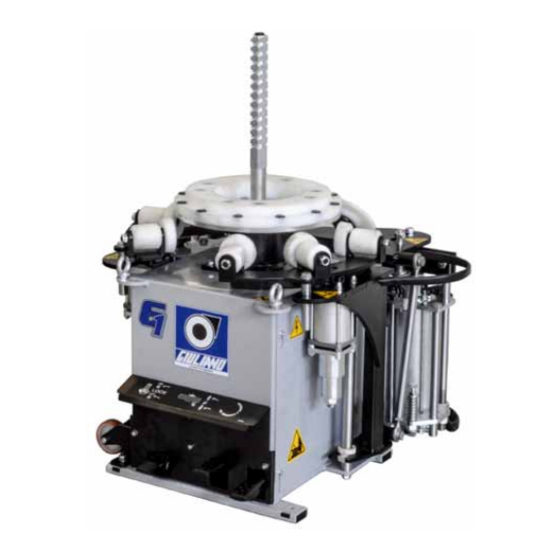
10.0 EQUIPMENT COMPONENTS Bead Lifting Lever Bead Breaker Tool Exagonal Blocking Device A Exagonal Cones Bead Blocking Breaker Device B Disc Centre-plate Antirotation Bead Breaker Disc Roller Roller Transport Pedal control unit Wheel... -
Page 11: Controls Description
11.0 CONTROLS DESCRIPTION Lock On/Off Antirotation Pin (ref. 5) Roller movementmand bead breaker Clockwise and anti-clockwise centre-plate (ref. 4) rotation pedal control Any test must be operated with no tyre onto the machine. Mind any component which could interfere with machine testing operations. -
Page 12: Tyre Demounting
12.0 TYRE DEMOUNTING ATTENTION: Deflate the tyre before to start the process Push the locking pedal (ref. 1), and insert the exagonal blocking device by pressing the button (A) to block the wheel on the Tyre Changer (fig. 1). When release the locking pedal (ref. 3), the exagonal blocking de- vice blocks the wheel (fig. -
Page 13: Tyre Mounting
13.0 TYRE MOUNTING - Lube 3 cm thickness along the whole internal surface of the rim and internal and external surface of tyre beads. Avoid contacts between the lubricating paste and the valve sensor, if any. For mount the yre on the Wheel block the rim as for instructions at page 12. -
Page 14: Standard Accessories
14.0 STANDARD ACCESSORIES Bead Breaker Tool A Bead Lifting Lever Bead Breaker Tool B Exagonal blocking devices A and B Cones... -
Page 15: Re-Positioning
15.0 RE-POSITIONING To re-position the Tyre-Changer in a new workplace: secure the moving parts (i.e. the bead pressing arms, etc.) discon- nect all the power sources and install it again following all the instruction per chapter 9.0 of this manual. Connections to power sources and connection &... -
Page 16: Maintenance
19.0 MAINTENANCE 19.1 Standard Maintenance Routine maintenance according to the following instructions is of crucial importance to ensure the correct operation and lasting life of the Tyre-Changer. Before starting any maintenance job, disconnect the electrical power supply by unplugging the machine from the main electrical feeding and disconnect it from the pneumatic supply by shutting off the valve. -
Page 17: Troubleshooting Chart
20.0 TROUBLESHOOTING CHART PROBLEM CAUSE SOLUTION Centre-plate does not rotate 1) Missing electrical feeding 1) Turn power on 2) Power cord missing or not plugged 2) Check cord or plug in correctly 3) Fuses blown or differential disa- 3) Replace fuses or enable bled differential 4) Drive belt loosened or damaged... -
Page 18: Wiring Diagrams
21.0 WIRING DIAGRAMS POWER SUPPLY LINE 230V 1Ph 50/60Hz MOTOINVERTER MOTOR 1HP INSTALLATION BY THE USER Imax=16A Id=30mA ELECTRONIC BOARD PLUG NEMA L6-20P Plug and socket Molex Minifit PEDAL SWITCH 12V SWITCH FUNCTION SLOW SPEED CLOCKWISE FAST SPEED CLOCKWISE SPEED COUNTERCLOCKWISE... -
Page 19: Pneumatic Diagrams
22.0 PNEUMATIC DIAGRAMS Ref. Description 4192727 VALVE 2037489 BEAD BREAKER CYLINDER 4193998 VALVE 2037275 INTERNAL BEAD BREAKER CYLINDER 2038807 BEAD BREAKER VALVE 4192728 VALVE 2038847 VALVE AIR 2037549 CYLINDER ARM 4193997 VALVE 2037244 INTERNALE CYLINDER 2038806 LOCKING VALVE... -
Page 20: Service Reports
23.0 SERVICE REPORTS All the operations made on the machine in the course of time must be reported herebelow so as to have an updated situation of the efficiency of the machine. The user must carry out both cleaning and greasing operations according to the instructions given in this manual. Any operation concerning the replacement of parts is strictly reserved to authorized and trained staff. - Page 21 Date Signature Intervention Replacements Notes Date Signature Intervention Replacements Notes Date Signature Intervention Replacements Notes Date Signature Intervention Replacements Notes...
- Page 22 GIULIANO INDUSTRIAL S.p.a. - Via Guerrieri, 6 - 42015 Correggio (RE) ITALY...
Need help?
Do you have a question about the G1 SPORT and is the answer not in the manual?
Questions and answers