Table of Contents
Advertisement
Quick Links
Advertisement
Table of Contents

Related Manuals for GIULIANO Crossage


Summary of Contents for GIULIANO Crossage
- Page 1 Use and Maintenance instruction manual Ed.01/11 Cod.3019988 Original Instructions...
- Page 2 CE DECLARATION OF CONFORMITY DECLARATION DE CONFORMITE CE CE - ÜBEREINSTIMMUNG GIULIANO INDUSTRIAL S.p.a. - Via Guerrieri, 6 - 42015 Correggio (RE) ITALY dichiara sotto la propria esclusiva responsabilità che il prodotto: declare on our own responsibility that the product: Déclare sous son propre responsabilité...
- Page 3 RoHS DECLARATION OF CONFORMITY DECLARATION DE CONFORMITE RoHS RoHS - ÜBEREINSTIMMUNG GIULIANO INDUSTRIAL S.p.A. - Via Guerrieri, 6 - 42015 Correggio (RE) ITALY dichiara sotto la propria esclusiva responsabilità che il prodotto: declare on our own responsibility that the product: Déclare sous son propre responsabilité...
- Page 4 GIULIANO INDUSTRIAL S.p.A. - Via Guerrieri, 6 DICHIARAZIONE DI CONFORMITA’ RAEE - 42015 Correggio (RE) ITALY dichiara sotto la propria esclusiva responsabilità che il prodotto: RAEE DECLARATION OF CONFORMITY declare on our own responsibility that the product: DECLARATION DE CONFORMITE RAEE Déclare sous son propre responsabilité...
-
Page 5: Table Of Contents
INDEX IINTRODUCTION..............................7 DETAILS OF THE TYRE CHANGER........................7 1 .0_Part identification............................8 2.0_Description of the machine’s controls......................9 2.1_Control panel.............................10 3.0_Danger warnings............................12 4.0_General information............................13 5.0_General safety instructions..........................13 6.0_Safety devices...............................14 7.0_Transport................................14 8.0_Unpacking..............................14 9.0_Installation..............................15 9.1_Spaces required to position the machine..................15 9.2_Positioning............................15 9.3_Commissioning..........................16 10.0_Operational test............................17 11.0_Identifying and checking the rim and tyre....................18 12.0_Positioning the valve...........................19 13.0_Tyre classification............................19 14.0_Clamps for conventional tyres........................20... - Page 6 22.0_Oil treatment..............................37 22.1_General precautions.........................37 22.2_First Aid instructions.........................37 22.3_Disposing of old oil...........................37 22.4_Oil spillages or leakages........................37 23.0_Technical specifications..........................38 24.0_Trouble shooting............................39 Wiring diagrams..............................42 Pneumatic diagrams..............................44 Maintenance register.............................48...
-
Page 7: Iintroduction
INTRODUCTION We thank you for purchasing one of our tyre changers, which are particularly suitable for mounting/demounting standard tyres and “run flat” tyres. The machine is manufactured exploiting the best of quality principles. To ensure correct operation and long life of the machine, all you need to do is follow these simple instructions, which shall be read and fully understood in every single part. -
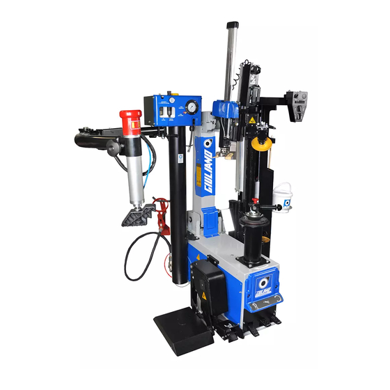
Page 8: Part Identification
1.0_PART IDENTIFICATION Inflation Control panel Press Arm Bead breaking disc Spindle flange Wheel Positioner Pedal controls (optional) -
Page 9: Description Of The Machine's Controls
2.0_DESCRIPTION OF THE MACHINE’S CONTROLS The controls of the LIFT (N) are used to lift and lower the wheel. The rotation pedal controls (M) are used to turn the spindle flange clockwise/anti- clockwise. The arm tipping pedal controls (L) are used to move the vertical arm in and out of the working position. -
Page 10: Control Panel
2.1_Control panel A) Selector used to block the horizontal approaching movement (buttons C and D) of the bead breaking carriage and to activate the “over stroke” (button G) B) Button used to release the bead breaking carriage from the work position C) Button used to approach the bead breaking carriage “forwards”... - Page 11 Extractable pneumatic tool, operated manually. Push the lever H down to be able to take the tool out of its seat and push it up to put it back in position. The bead presser is used to facilitate the mounting and de- mounting phases.
-
Page 12: Danger Warnings
3.0_DANGER WARNINGS Cod. 3005742 Cod. 3019744 Cod.3005411 Cod. 3005416 Cod. 3019742 Cod. 3019740 Cod. 3019739 Cod. 3019741 Cod. 3008944 Cod. 3001104 Cod. 3005410 Cod. 3000048 Cod. 3005414 Cod. 3019743 Cod. 3019736 Cod. 3019737 Cod. 3019738... -
Page 13: General Information
4.0_GENERAL INFORMATION The tyre changer is designed to demount and mount tyres of cars and light vehicles with rims of 10” to 34” and maxi- mum diameter of 1200 mm. The tyre changer is designed to demount and mount conventional tyres of cars, light industrial vehicles, tyres of new generation type “self-supporting”... -
Page 14: Safety Devices
WATER FOAM ex- POWDER extin- extin- tinguisher extin- guisher guisher guisher DRY materials FLAMMABLE liquids ELECTRICAL equipment 6.0_SAFETY DEVICES The tyre changer is equipped with safety devices that are designed to guarantee the safety of the machine operator: - Pneumatic safety valve, arranged inside the machine that prevents the pressure from exceeding 4 bar during inflation. - Pressure regulator and gauge that limits the maximum pressure of the circuit to 10 bar. -
Page 15: Installation
9.0 INSTALLATION 9.1 Spaces required to position the machine When choosing the place of installation, remember to observe current standards on safety at the workplace. - The tyre changer needs to be connected to the electrical mains and to the compressed air supply. The machine should therefore be installed near such energy sources. -
Page 16: Commissioning
9.3_Commissioning Before you connect the machine electrically, check the nameplate fitted on it to make sure the electrical power supply to which it will be connected matches the electrical arrangement of the manufacturer. Work on the electrical system, even if trivial, must be carried out by professionally qualified personnel. -
Page 17: Operational Test
10.0_OPERATIONAL TEST - Press pedal M and the wheel positioner P should raise; to lower the wheel positioner, lift the same pedal upwards. - Press pedal L on L2 and the spindle flange R should turn clockwise. Press the pedal L on L1 and the spindle flange R should turn anti-clockwise. NB: If the flange should turn in the opposite direction to that indicated, you need to invert two wires on the plug, if it is three-phase. -
Page 18: Identifying And Checking The Rim And Tyre
11.0_IDENTIFYING AND CHECKING THE RIM AND TYRE Before you start to demount the tyre, it is of CRUCIAL IMPORTANCE to identify the measurements of the rim and of the tyre. Also make sure neither is damaged. ATTENTION: These procedures are very important and are to be performed to reduce risks of the tyre bursting when re-mounting the tyre on the rim and inflating it. -
Page 19: Positioning The Valve
12.0_POSITIONING THE VALVE Fig. 6 shows a rim in the form of a clock, so that, following the various processing phases described hereafter, (chapter entitled Mounting and Demounting), you can position the valve and its sensor correctly so as not to damage them. ATTENTION: To avoid damaging the valve and the pressure sensor, if the latter is installed, you must always arrange the valve... -
Page 20: Clamps For Conventional Tyres
14.0_CLAMPS FOR CONVENTIONAL RIMS A conventional rim is a wheel of a vehicle with rim of steel or light aluminium alloy, with a drop centre hole and channel near the outer edge of the rim. For other types of rims, please consult the chapters on the accessories available on request. - Using a special tool, remove any counterweights on the rim, being particularly careful not to damage the rim. -
Page 21: Bead Breaking
There is a driving pin on the spindle flange that is to be fitted in one of the rim clamping holes. Position the ring nut hub and the appropriate nose on the spindle flange in relation to the diameter of the drop centre hole. - Page 22 - Position the bead breaking disc (as illustrated in fig. “Phase 1”) to remove the top part of the tyre. To do this, move the two levers to- gether (re. A), accompany the disc support with your hand upwards and release the two levers so as to block the disc support. - Position the bead breaking carriage on the tyre using control but- tons C and D on the control panel.
- Page 23 - When turning the tyre, push the bead breaking disc up under the edge of the rim and then press and hold down the “over stroke” fun- ction button G and continue pushing the disc up (in sections) until the bead of the tyre has come away from the rim. - Once the bead breaking disc has created enough space, start to lubricate carefully, both on the internal part of the rim and on the bead of the tyre;...
-
Page 24: 4.2_Demounting Standard Tyres
14.2_DEMOUNTING STANDARD TYRES - Proceed as follows to demount the tyre: - Turn the spindle until the valve is in the “1 o’clock” position (roughly 10 cm after the tool). - Position the assembly head over the rim and block it using control button K (ref. 1 fig. 10a/b); this will block the operating arm and the horizontal arm;... -
Page 25: Mounting Standard Tyres
- Press the rotation pedal (L) to turn the tyre clockwise by 360° until the upper bead is completely demounted (fig. 12) - Turn the spindle until the valve is in the “1 o’clock” position. - Take the tool out again, position the second bead of the tyre over the tool and raise the tool, using lever H. - Page 26 Fig. 15 Make sure the bead of the tyre rests on the “shoe” shaped part of the tool and under the grub screw in the opposite part of the tool. -Press the rotation pedal (L) to turn the tyre clockwise by 360° -Manually press the tyre in the “5 o’clock”...
-
Page 27: Demounting Run-Flat Uhp Tyres
15.0_DEMOUNTING RUN-FLAT (Self-supporting) and UHP (Low profile) TYRES with WdK kit - Proceed as follows to demount the tyre: - Turn the spindle to move the valve to the “1 o’clock” position (roughly 10 cm after the tool). - Position the assembly head over the rim and block it using control button K (ref. 1 fig. 10a/b); this will block the operating arm and the horizontal arm;... - Page 28 Start inserting the tool in the tyre, possibly also using the bead breaking disc, positio- ning it in the top part, without forcing the side of the tyre excessively. NB. If you have difficulty in positioning the tyre on the end of the tool, you need to turn the spindle until it positions itself correctly.
-
Page 29: Mounting Run-Flat Uhp Tyres
15.1_MOUNTING RUN-FLAT (self-supporting) UHP (Low Profile) tyres with WdK kit - Check the rim and the tyre, as described in the specific section of this ma- nual. - If the rim has been removed, clamp the wheel on the spindle flange, as de- scribed in the WHEEL CLAMPING section Fig. - Page 30 Fig. 27 -Position the tyre horizontally on the rim, slightly tilted downwards in the “3 o’clock” position (fig. 27). - Insert and secure the clamp with the rubber protector suitable for the type of rim ( • iron rim •• alloy rim ••• alloy rim with protruding spokes). - If necessary, exploit the top disc positioned near the clamp (fig.
-
Page 31: Inflation
16.0_INFLATION Tyres are to be inflated with utmost caution. Strictly follow the instructions hereafter because the tyre changer is NOT designed and manufactured to safeguard the user (nor anybody else standing near the machine) if the tyre should accidentally burst. ATTENTION! If the tyre bead fails to fit in place during inflation at the maximum pressure of 3.3 bar, you need to repeat the bead breaking and lubricating procedure of the tyre itself and then try inflating again. -
Page 32: 7.0_Machine Supply
17.0_MACHINE SUPPLY Standard supply 17.1_OPTIONAL ACCESSORIES Flange FRU/345 C SPECIAL (for clamping rims without drop centre hole) The flange FRU/345 C special can be used on all wheels with any number of clamping holes. Fit the flange on the spindle making sure to position it carefully, securing it with the 2 knobs supplied. - Page 33 Flangia FPM/345 (for clamping rims with back-to-front channel, in other words, rims with the channels opposite the flanging of the rim) The flange FPM/345 can be used on all wheels with any number of clamping holes. Select the pins of the shape and length required and secure them on the connecting rods.
- Page 34 NB.: The flange FPM 345 can be used to clamp the wheels without using the nose. Position the wheel on the spindle, as described in the section entitled CLAMPING STANDARD WHEELS, position the flange on the wheel, matching-up the pins with the securing holes, avoiding that where the driving pin is already inserted, then tighten with the pin and nose.
-
Page 35: 8.0_Repositioning
18.0_RE-POSITIONING To re-position the tyre changer in a new workplace, you need to block the mobile parts (i.e. bead presser etc.) disconnect all the power sources and install it again following all the instructions given in chapter 9.0 “INSTALLATION” of this manual. Connections to energy sources and connections and inspections of the safety systems must be carried out by experts. -
Page 36: Routine Maintenance
In particular, THE MANUFACTURER is not liable for claims deriving from the use of non-original spare parts or for damages caused through removal or tampering with safety systems. At the achievement of 5 years from the date of installation and commissioning, the product must be re- viewed in its entirety. -
Page 37: Oil Treatment
22.0_OIL TREATMENT OIL IS HIGHLY POLLUTANT! Do not throw away outdoors or pour on the ground 22.1_General precautions - Avoid direct and prolonged contact with skin. - Avoid the formation of oil mists in the air. - Avoid splashing. - Wear appropriate clothing, gloves and goggles to protect against oil splashes. - Do not use greasy rags. -
Page 38: Technical Specifications
23.0_TECHNICAL SPECIFICATIONS TECHNICAL SPECIFICATIONS Rim clamping 10” - 34” Max. wheel diameter 47” 1200 mm Tyre width 16” 410 mm Max. “Lift” capacity 80 Kg Force of bead breaking cylinder (10 bar - 145 Psi) 12037 N Service pressure 8 - 10 bar (116 - 145 psi) Power supply voltage 400V - 3Ph... -
Page 39: Trouble Shooting
24.0_TROUBLE SHOOTING (ADVANCED) OPERATING ANOMALIES PROBLEM CAUSE ISOLUTION The self-centring chuck does not turn 1) No electrical power supply 1) Check the socket on the wall 2)Power supply plug not plugged-in 2) Plug the machine into the correctly mains 3)Fuses blown 3) Replace the fuses 4)Belt loose or broken 4) Tension the belt or replace it... - Page 40 PROBLEM CAUSE SOLUTION The hook that unlocks the structure of the 1) No pneumatic supply 1) Check the line pressure bead breaker does not open 2) Control valve broken 2) Replace the valve 3) Silencers obstructed 3) Clean the silencer or replace 4) Cylinder gasket broken 4) Replace the gaskets 5) Pilot valve broken or malfunctio-...
-
Page 41: Wiring Diagrams
WIRING DIAGRAMS... -
Page 44: Pneumatic Diagrams
PNEUMATIC DIAGRAMS... - Page 47 SERVICE REGISTER...
-
Page 48: Maintenance Register
REGISTRO DI CONTROLLO DEGLI INTERVENTI/CHECK RECORD OF INTERVEN- TIONS/REGISTRE DE CONTROLE DES INTERVENTIONS/WARTUNGSREGISTER In questo registro devono essere annotati tutti gli interventi effettuati sulla macchina nel corso del tempo, al fine di avere sempre la situazione aggiornata sullo stato di efficienza della macchina stes- Si ricorda che gli interventi di pulizia e lubrificazione sono a cura dell'utente, seguendo le istruzioni riportate nel presente manuale. - Page 49 Data Intervento Eventuali pezzi sostituiti Note Firma Date Operation Part eventually replaced Remarks Signature Date Intervention Replacement eventuel de pieces Remarques Signature Datum Wartungsarbeit Ggf. ersetzte Anm. Unterschrift Data Intervento Eventuali pezzi sostituiti Note Firma Date Operation Part eventually replaced Remarks Signature Date...
- Page 50 GIULIANO INDUSTRIAL S.p.A. Via Guerrieri, 6 - 42015 Correggio (RE) ITALY Tel. +39.0522.731111 - Fax +39.0522.633109 http://www.giuliano-automotive.com E-mail: info@giuliano-automotive.com...
Need help?
Do you have a question about the Crossage and is the answer not in the manual?
Questions and answers