Table of Contents
Advertisement
Available languages
Available languages
Quick Links
Advertisement
Chapters
Table of Contents

Subscribe to Our Youtube Channel
Related Manuals for ProLights TRIBE VISUALGOB


Summary of Contents for ProLights TRIBE VISUALGOB
- Page 1 VISUALGOB LED GOBO PROJECTOR MANUALE UTENTE USER MANUAL IT - EN...
- Page 2 Music & Lights S.r.l. si riserva ogni diritto di elaborazione in qualsiasi forma delle presenti istruzioni per l’uso. La riproduzione - anche parziale - per propri scopi commerciali è vietata. Al fine di migliorare la qualità dei prodotti, la Music&Lights S.r.l. si riserva la facoltà di modificare, in qualunque momento e senza preavviso, le specifiche menzionate nel presente manuale di istruzioni.
-
Page 3: Table Of Contents
VISUALGOB INDICE Sicurezza Avvertenze generali Attenzioni e precauzioni per l’installazione 1 Introduzione 1. 1 Descrizione 1. 2 Specifiche tecniche 1. 3 Elementi di comando e di collegamento 2 Installazione 2. 1 Montaggio 3 Funzioni e impostazioni 3. 1 Funzionamento 3. 2 Impostazione base 3. -
Page 4: Sicurezza
VISUALGOB ATTENZIONE! Prima di effettuare qualsiasi operazione con l’unità, leggere con attenzione questo manuale e conservarlo accuratamente per riferimenti futuri. Contiene informazioni importanti riguardo l’installazione, l’uso e la manutenzione dell’unità. SICUREZZA Avvertenze generali • I prodotti a cui questo manuale si riferisce sono conformi alle Direttive della Comunità Europea e per- tanto recano la sigla . -
Page 5: Introduzione
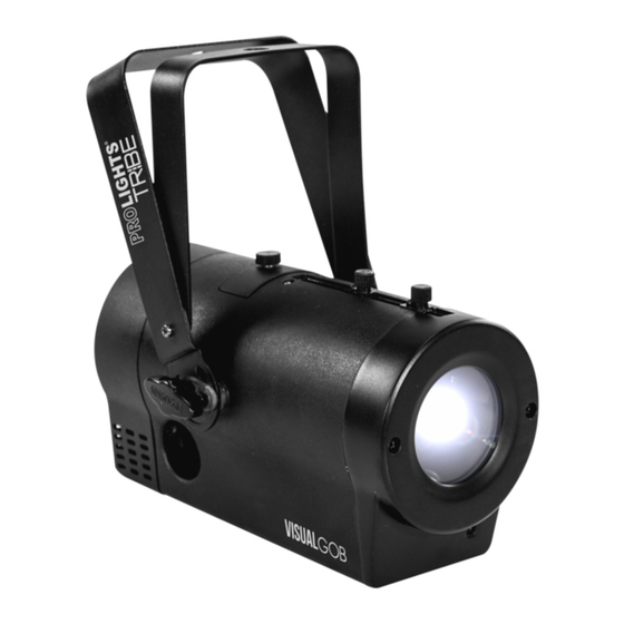
VISUALGOB - 1 - INTRODUZIONE 1.1 DESCRIZIONE VISUALGOB è un proiettore di immagini compatto dotato di sorgente luminosa a LED, concepito per re- inventare un nuovo standard nel campo dei proiettori di gobo. Il sistema ottico ad alta efficienza è stato studiato combinando un chip LED bianco da 34W con uno speciale sistema zoom da 10°-24°, risultando incredibilmente luminoso, compatto ed energy-saving. - Page 6 VISUALGOB Disegno tecnico Fig.1...
-
Page 7: Elementi Di Comando E Di Collegamento
VISUALGOB 1.3 ELEMENTI DI COMANDO E DI COLLEGAMENTO Pannello Posteriore Fig.2... - Page 8 VISUALGOB 1. STAFFA DI MONTAGGIO 9. POWER IN spina da pannello VDE per 2. VITE DI ACCESSO AL VANO GOBO per cambiare il collegamento ad una presa di rete manualmente la figura da proiettare (100-240V~/50-60Hz) tramite il cavo di rete 3.
-
Page 9: Installazione
VISUALGOB - 2 - INSTALLAZIONE 2.1 MONTAGGIO Il VISUALGOB può essere collocato su un piano solido. Inoltre, grazie alle possibilità di fissaggio sulla dop- pia staffa (fig.3), l’unità può essere montata anche a testa in giù, su una traversa. Per il fissaggio occorrono dei supporti robusti per il montaggio. -
Page 10: Funzioni E Impostazioni
VISUALGOB - 3 - FUNZIONI E IMPOSTAZIONI 3.1 FUNZIONAMENTO Per accendere il VISUALGOB, inserire la spina del cavo di alimentazione in una presa di rete (100-240V~/50- 60Hz). L’unità può essere comandata da un’unità DMX di comando luce oppure svolgere autonomamente il suo programma. -
Page 11: Struttura Menu
VISUALGOB 3.3 STRUTTURA MENU MENU ð 2 - CH d1 - d512 Selects the DMX Mode and DMX starting value ð Gobo StoP Select the static gobo effect ð L - SP L0 - L255 Select the ounterclockwise rotation effect ð... -
Page 12: Indirizzamento Dmx
VISUALGOB 3.8 INDIRIZZAMENTO DMX Per poter comandare il VISUALGOB con un’unità di comando luce, occorre impostare l’indirizzo di start DMX per il primo canale DMX. Se, per esempio, sull’unità di comando è previsto l’indirizzo 33 per coman- dare la funzione del primo canale DMX, si deve impostare sul VISUALGOB l’indirizzo di start 33. Le altre funzioni del pannello saranno assegnate automaticamente agli indirizzi successivi. -
Page 13: Collegamenti Della Linea Dmx
VISUALGOB 3.10 COLLEGAMENTI DELLA LINEA DMX La connessione DMX è realizzata con connettori standard XLR. Utilizzare cavi schermati, 2 poli ritorti, con impedenza 120Ω e bassa capacità. Per il collegamento fare riferimento allo schema di connessione riportato di seguito: DMX - OUTPUT DMX - INPUT Presa XLR Spina XLR... -
Page 14: Funzionamento Tramite Il Controller Irc
VISUALGOB 3.12 FUNZIONAMENTO TRAMITE IL CONTROLLER IRC Per comandare Il VISUALGOB con il telecomando a raggi infrarossi: • Premere il tasto MENU fino a quando sul display non appare SET, quindi premere ENTER per confermare. • Utilizzare i tasti UP/DOWN per selezionare On oppure Off a seconda che si voglia attivare oppure disatti- vare il controllo con il telecomando a raggi infrarossi. -
Page 15: Manutenzione
VISUALGOB - 4 - MANUTENZIONE 4.1 MANUTENZIONE E PULIZIA DEL SISTEMA OTTICO • Durante gli interventi, assicurarsi che l’area sotto il luogo di installazione sia libera da personale non qualificato. • Spegnere l’unità, scollegare il cavo di alimentazione ed aspettare finché l’unità non si sia raffreddata. •... - Page 16 All rights reserved by Music & Lights S.r.l. No part of this instruction manual may be reproduced in any form or by any means for any commercial use. In order to improve the quality of products, Music&Lights S.r.l. reserves the right to modify the characteristics stated in this instruction manual at any time and without prior notice.
-
Page 17: Visualgob
VISUALGOB TABLE OF CONTENTS Safety General instructions Warnings and installation precautions 1 Introduction 1. 1 Description 1. 2 Technical specifications 1. 3 Operating elements and connections 2 Installation 2. 1 Mounting 3 Functions and settings 3. 1 Operation 3. 2 Basic 3. -
Page 18: General Instructions
VISUALGOB WARNING! Before carrying out any operations with the unit, carefully read this instruction manual and keep it with cure for future reference. It contains important information about the installation, usage and maintenance of the unit. SAFETY General instruction • The products referred to in this manual conform to the European Community Directives and are there- fore marked with . -
Page 19: Introduction
VISUALGOB - 1 - INTRODUCTION 1.1 DESCRIPTION VISUALGOB is a compact image projector with LED light source, designed to re-invent a new standard in the field of gobo projectors. The high-efficient optical system has been studied by combining a 34W white LED chip with a special 10°-24°... - Page 20 VISUALGOB Technical drawing Fig.1...
-
Page 21: Operating Elements And Connections
VISUALGOB 1.3 OPERATING ELEMENTS AND CONNECTIONS Rear panel Fig.2... - Page 22 VISUALGOB 1. MOUNTING BRACKET 9. POWER IN mains plug for connection to a 2. GOBO SCREW to manually change the socket (100-240V~/50-60Hz) via the supplied projected figure mains cable. The support for the mains fuse is 3. FOCUS AND ZOOM ADJUSTING SCREW to located near the mains plug.
-
Page 23: Installation
VISUALGOB - 2 - INSTALLATION 2.1 MOUNTING VISUALGOB may be set up on a solid and even surface. The unit can also be mounted upside down to a cross arm. For fixing, stable mounting clips are required. The mounting place must be of sufficient stability and be able to support a weight of 10 times of the unit’s weight. -
Page 24: Functions And Settings
VISUALGOB - 3 - FUNCTIONS AND SETTINGS 3.1 OPERATION Connect the supplied main cable to a socket (100-240 VAC-50/60 Hz). Then the unit is ready for operation and can be operated via a DMX controller or it independently performs its show program. To switch off, disconnect the mains plug from the socket. -
Page 25: Menu Structure
VISUALGOB 3.3 MENU STRUCTURE MENU ð 2 - CH d1 - d512 Selects the DMX Mode and DMX starting value ð Gobo StoP Select the static gobo effect ð L - SP L0 - L255 Select the ounterclockwise rotation effect ð... -
Page 26: Dmx Control
VISUALGOB channel, adjust the start address 33 on the VISUALGOB. The other functions of the light effect panel are then automatically assigned to the following addresses. An example with the start address 33 is shown below: Number of Start address DMX Address Next possible start Next possible start... -
Page 27: Connection Of The Dmx Line
VISUALGOB 3.10 CONNECTION OF THE DMX LINE DMX connection employs standard XLR connectors. Use shielded pair-twisted cables with 120Ω imped- ance and low capacity. The following diagram shows the connection mode: DMX - INPUT DMX - OUTPUT XLR plug XLR socket Pin1 : GND - Shield Pin2 : - Negative Pin3 : + Positive... -
Page 28: Operation Through The Irc Controller
VISUALGOB 3.12 OPERATION THROUGH THE IRC CONTROLLER To control the VISUALGOB with the infrared remote control: • Press the button MENU repeatedly until SET, then press button ENTER to confirm. • Using UP/DOWN button to select On or Off to enable or disable the infrared remote control. •... -
Page 29: Maintenance
VISUALGOB - 4 - MAINTENANCE 4.1 MAINTENANCE AND CLEANING THE UNIT • Make sure the area below the installation place is free from unwanted persons during setup. • Switch off the unit, unplug the main cable and wait until the unit has cooled down. •... - Page 32 MUSIC & LIGHTS S.r.l. Via Appia, km 136,200 - 04020 Itri (LT) - ITALY Phone +39 0771 72190 - Fax +39 0771 721955 www.musiclights.it - email: info@musiclights.it ISO 9001:2008 Certified Company...
Need help?
Do you have a question about the TRIBE VISUALGOB and is the answer not in the manual?
Questions and answers