
Related Manuals for Advantech HPC-7480


Summary of Contents for Advantech HPC-7480
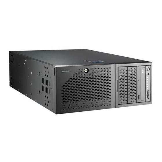
- Page 1 User Manual HPC-7480 4U Tower/Rackmount Chassis for EATX Serverboard with 8 Hot-swap Hard Drive Cages...
- Page 2 No part of this manual may be reproduced, copied, translated or transmitted in any form or by any means without the prior written permission of Advantech Co., Ltd. Information provided in this manual is intended to be accurate and reliable. How- ever, Advantech Co., Ltd.
- Page 3 Caution: Always completely disconnect the power cord from your chassis when- ever you work with the hardware. do not make connections while the power is on. sensitive electronic components can be damaged by sudden power surges HPC-7480 User Manual...
- Page 4 Advantech has come to be known. Your satisfaction is our primary concern. Here is a guide to Advantech's cus- tomer services.
- Page 5 It should be free of marks and scratches and in perfect working order upon receipt. As you unpack the HPC-7480, check it for signs of ship- ping damage. (For example, damaged box, scratches, dents, etc.) If it is damaged or it fails to meet the specifications, notify our service department or your local sales representative immediately.
- Page 6 HPC-7480 User Manual...
-
Page 7: Table Of Contents
2.3.1 Accessing and Installing Hard Drives ........... 7 Figure 2.2 Removing Hard Drive Trays ........7 Installing Fixed Hard Drives in HPC-7480 Chassis Models ...... 7 2.4.1 Disconnecting the Chassis from the Power Source...... 7 Figure 2.3 Removing Hard Drive Trays ........8 Installing Hard Drives into the Drive Trays.......... - Page 8 Rear Connectors and LED Indicators Rear Connectors..... 29 Figure 4.8 Rear Connectors ............29 Table 4.16: Rear SATA Connectors..........29 Figure 4.9 Rear LEDs..............30 Table 4.17: Rear LED Indicators ..........30 Appendix A Chassis Screws......... 31 Chassis Screws ..................32 HPC-7480 User Manual viii...
-
Page 9: Chapter 1 General Information
Chapter General Information... -
Page 10: Introduction
Introduction HPC-7480 is a 4U-high rackmount industrial computer chassis for high-performance and high-capacity computing applications. It meets a variety of application needs for filing, printing, e-mail and web serving. This powerful computing platform is suitable for mission-critical computer telephony applications, industrial automation, and fac- tory management. -
Page 11: Dimension Diagram
Dimension Diagram 645.60 [25.42] 177 [6.97] unit = mm [inch] Figure 1.1 Dimension Diagram HPC-7480 User Manual... - Page 12 HPC-7480 User Manual...
-
Page 13: Chapter 2 System Setup
Chapter System Setup... -
Page 14: Overview
Overview The following procedures instruct users on how to install a backplane/motherboard, add-on cards and disk drives into the HPC-7480. Please also refer to Appendix A, Exploded Diagram, for the detailed parts of HPC-7480. Caution! Use caution when installing or operating the components with the chas- sis open. -
Page 15: Accessing The Hot-Swappable Drive Trays
2.4.1 Disconnecting the Chassis from the Power Source Turn off all peripheral devices and turn off the power supply to the HPC-7480. Disconnect the AC power cord from the system. Disconnect all cables and label the cables for easy identification. -
Page 16: Installing Hard Drives Into The Drive Trays
CD, IDE, DVD, tape and floppy drives. The chassis may be rotated from a vertical tower position, to a horizontal rack mounting position to accommodate use of these devices. The following configurations may be used in the HPC-7480 chassis: ... -
Page 17: Removing The Storage Module
Remove the screws and drive tray brackets from the drive trays. Install the 5.25” devices into the storage module. Replace the module back into the chassis. Ensure that the storage module is securely locked into position. Figure 2.6 Installing 5.25" Devices into the Storage Module HPC-7480 User Manual... -
Page 18: Removing And Replacing The System Fans
2.7.1 Standard Cooling Systems HPC-7480 chassis include mid-chassis cooling fans, rear cooling fans and an air shroud to channel air within the chassis. Removing and Replacing Mid-chassis Fans... -
Page 19: Installing The Motherboard
Do not exceed eight pounds of torque per square inch when tightening down the motherboard. Replace the middle and rear system fans as directed in section 2.7. Figure 2.9 Installing the Motherboard HPC-7480 User Manual... -
Page 20: Installing Expansion Cards
2.10.1 Installing Expansion Cards Locate the release tab on the top of the expansion card bracket Gently apply pressure on the middle of the release tab to unlock the bracket as shown. Figure 2.10 Installing Expansion Cards HPC-7480 User Manual... -
Page 21: Chapter 3 Operation
Chapter Operation... -
Page 22: The Front Panel
The following diagram defines each component of the front LED panel. Figure 3.1 Front control panel Power Button System Reset Power Indicator HDD Activity Indicator LAN1 Indicator LAN2 Indicator CPU Temperature/Fan Failure Indicator Power Failure Indicator USB Port USB Port HPC-7480 User Manual... -
Page 23: Control Panel Buttons
Reset: The reset button is used to reboot the system. Control Panel LEDs The control panel located on the front of the HPC-7480 chassis has five LEDs. These LEDs provide you with critical information related to different parts of the system. This section explains what each LED indicates when illuminated and any corrective action you may need to take. - Page 24 Finally, verify that the heatsinks are installed properly. This LED will remain flashing or on as long as the overheat condition exists. Power Fail: Indicates a power failure to the system's power supply units. HPC-7480 User Manual...
-
Page 25: Chapter 4 Sata/Sas Backplane
Chapter SATA/SAS Backplane... -
Page 26: Sas Backplane Specifications
4.1.4 Introduction to the SAS Backplane The SAS backplane has been designed to utilize the most up-to-date technology available, providing your system with reliable, high-quality performance. HPC-7480 User Manual... -
Page 27: Front Connectors
#4. Backplane Main Power Connectors The 4-pin connectors, designated JP10 and JP13, provide power to the backplane. See the table below for pin definitions. Table 4.2: Backplane Main Power 4-Pin Connector Pin Definition +12 V 2 and 3 Ground +5 V HPC-7480 User Manual... - Page 28 The SAS ports are used to connect the SAS drive cables. The 8 ports are designated #0 - #7. Each port is also compatible with SATA drives. However, do NOT mix SAS and SATA drives in the same enclosure HPC-7480 User Manual...
-
Page 29: Front Jumper Locations And Pin Definitions
JP34 JP36 JP37 JP29 M 8 7 M 9 6 M 8 6 M 9 7 M M 3 UPER SAS743TQ M M 2 REV 3.00 JP18 +12V +12V GND +5V JP43 JP42 Figure 4.2 Front Jumpers HPC-7480 User Manual... - Page 30 Reset MG9072 Chip Reset Closed: Disabled *The buzzer sound indicates that a condition requiring immediate attention has occurred. The buzzer alarm is triggered by the following conditions: Hard drive failure Fan failure System temperature over 45° Celsius. HPC-7480 User Manual...
- Page 31 # 4 - 7 Sideband #2 C #2 4.1.7.4 Front LED Indicators OH/Drive Fail LED Figure 4.3 Front Panel LEDs Table 4.8: Front Panel LEDs State Specification Overheat/drive failure LED indicator(Red light: flashing. Buzzer: On, if activated) HPC-7480 User Manual...
-
Page 32: Rear Connectors And Led Indicators
SAS #6 SAS/SATA HHD #6 SAS #7 SAS/SATA HHD #7 Table 4.10: Rear LED Indicators Rear LED Hard Drive Activity Failure LED SAS #0 SAS #1 SAS #2 SAS #3 SAS #4 SAS #5 SAS #6 SAS #7 HPC-7480 User Manual... -
Page 33: Sata Backplane Specifications
4.2.4 Introduction to the SATA Backplane The SATA backplane has been designed to utilize the most up-to-date technology available, providing your system with reliable, high-quality performance. HPC-7480 User Manual... -
Page 34: Front Connectors And Jumpers
See the table below for pin definitions. Table 4.12: Backplane Main Power Connector Pin Definition +12 V 2 and 3 Ground +5 V ackplane Main Power 4-Pin Connector Pin# De.nition 1 +12V 2 and 3 4 Ground +5V HPC-7480 User Manual... -
Page 35: Front Jumper Locations And Pin Definitions
Front Jumper Locations and Pin Definitions JP18 JP25 Figure 4.6 Front Jumpers Table 4.14: Socket Settings Jumper Setting Note Open: No Reset (Default) JP18 Buzzer reset* Closed: Reset Open: 45°C JP25 1-2: 50°C (Default) Overheat temperature setting. 2-3: 55°C HPC-7480 User Manual... - Page 36 Connector Pins Jumper Setting *The buzzer sound indicates that a condition requiring immediate attention has occurred. The buzzer alarm is triggered by the following conditions: Hard drive failure System temperature over 45° Celsius. HPC-7480 User Manual...
-
Page 37: Rear Connectors And Led Indicators Rear Connectors
SATA HDD #0 SATA #1 SATA HDD #1 SATA #2 SATA HDD #2 SATA #3 SATA HDD #3 SATA #4 SATA HDD #4 SATA #5 SATA HDD #5 SATA #6 SATA HDD #6 SATA #7 SATA HDD #7 HPC-7480 User Manual... - Page 38 SATA HDD #0 ACT 1 SATA HDD #1 ACT 2 SATA HDD #2 ACT 3 SATA HDD #3 ACT 4 SATA HDD #4 ACT 5 SATA HDD #5 ACT 6 SATA HDD #6 ACT 7 SATA HDD #7 HPC-7480 User Manual...
-
Page 39: Appendix A Chassis Screws
Appendix Chassis Screws... -
Page 40: Chassis Screws
M5 x 12 mm[0.472] [0.157] [0.157] Washer for M5 M/B STANDOFFS M/B standoff M/B (CPU) 1/U M/B standoff Thumb screw 6-32 to 6-32 standoff 6-32 x 5 mm 6-32 x 5 mm M5 to 6-32 [0.197] [0.197] HPC-7480 User Manual... - Page 41 HPC-7480 User Manual...
- Page 42 No part of this publication may be reproduced in any form or by any means, electronic, photocopying, recording or otherwise, without prior written permis- sion of the publisher. All brand and product names are trademarks or registered trademarks of their respective companies. © Advantech Co., Ltd. 2011...
- Page 43 Mouser Electronics Authorized Distributor Click to View Pricing, Inventory, Delivery & Lifecycle Information: Advantech HPC-7480-66A1E...
Need help?
Do you have a question about the HPC-7480 and is the answer not in the manual?
Questions and answers