
Related Manuals for VIPA SPEED7 CPU 313SCDPM


Summary of Contents for VIPA SPEED7 CPU 313SCDPM
- Page 1 VIPA System 300S CPU-SC | 313-6CF13 | Manual HB140 | CPU-SC | 313-6CF13 | GB | 15-50 SPEED7 CPU 313SC/DPM...
- Page 2 VIPA GmbH Ohmstr. 4 91074 Herzogenaurach Telephone: +49 9132 744-0 Fax: +49 9132 744-1864 Email: info@vipa.com Internet: www.vipa.com 313-6CF13_000_CPU 313SC/DPM,1,GB - © 2015...
-
Page 3: Table Of Contents
VIPA System 300S Table of contents Table of contents General..................6 1.1 Copyright © VIPA GmbH ........... 6 1.2 About this manual.............. 7 1.3 Safety information.............. 8 Basics..................10 2.1 Safety information for users..........10 2.2 Operating structure of a CPU........... 10 2.2.1 General................. - Page 4 5.17 Memory extension with MCC......... 74 5.18 Extended know-how protection........75 5.19 MMC-Cmd - Auto commands......... 77 5.20 VIPA specific diagnostic entries........79 5.21 Control and monitoring of variables with test functions.. 94 Deployment I/O periphery............. 96 6.1 Overview................96 6.2 In-/Output area CPU 313-6CF13........
- Page 5 10.3 TIA Portal - Hardware configuration - I/O modules..199 10.4 TIA Portal - Hardware configuration - Ethernet PG/OP channel................. 200 10.5 TIA Portal - Include VIPA library........203 10.6 TIA Portal - Project transfer.......... 203 HB140 | CPU-SC | 313-6CF13 | GB | 15-50...
-
Page 6: General
General 1.1 Copyright © VIPA GmbH All Rights Reserved This document contains proprietary information of VIPA and is not to be disclosed or used except in accordance with applicable agree- ments. This material is protected by the copyright laws. It may not be repro-... -
Page 7: About This Manual
Tel.: +49 9132 744-1150 (Hotline) EMail: support@vipa.de 1.2 About this manual Objective and contents This manual describes the SPEED7 CPU-SC 313-6CF13 of the System 300S from VIPA. It contains a description of the construction, project implementation and usage. Product Order number as of state:... -
Page 8: Safety Information
General VIPA System 300S Safety information Guide to the document The following guides are available in the manual: An overall table of contents at the beginning of the manual References with page numbers Availability The manual is available in: printed form, on paper... - Page 9 VIPA System 300S General Safety information CAUTION! The following conditions must be met before using or commissioning the components described in this manual: – Hardware modifications to the process control system should only be carried out when the system has been disconnected from power! –...
-
Page 10: Basics
Operating structure of a CPU > General Basics 2.1 Safety information for users Handling of electro- VIPA modules make use of highly integrated components in MOS- static sensitive modules Technology. These components are extremely sensitive to over-vol- tages that can occur during electrostatic discharges. The following symbol is attached to modules that can be destroyed by electrostatic discharges. -
Page 11: Applications
VIPA System 300S Basics Operating structure of a CPU > Operands Cyclic processing Cyclicprocessing represents the major portion of all the processes that are executed in the CPU. Identical sequences of operations are repeated in a never-ending cycle. Timer processing Where a process requires control signals at constant intervals you can initiate certain operations based upon a timer, e.g. -
Page 12: Cpu 313-6Cf13
SIMATIC Manager or TIA Portal from Siemens. Here the instruction set of the S7-400 from Siemens is used. Modules and CPUs of the System 300S from VIPA and Siemens may be used at the bus as a mixed configuration. -
Page 13: General Data
PROFIBUS DP slave operation: Configuration via PROFIBUS sub module with ‘Operation mode’ slave in the hardware configura- tion. PtP functionality: Configuration as virtual PROFIBUS master system by including the VIPA SPEEDBUS.GSD. Integrated Ethernet The CPU has an Ethernet interface for PG/OP communication. After PG/OP channel assigning IP address parameters with your configuration tool, via the "PLC"... - Page 14 Basics VIPA System 300S General data Conformity and approval 2004/108/EG EMC directive Approval UL 508 Approval for USA and Canada others RoHS 2011/65/EU Product is lead-free; Restriction of the use of certain hazardous substances in electrical and electronic equipment Protection of persons and device protection...
- Page 15 VIPA System 300S Basics General data Mounting conditions Mounting place In the control cabinet Mounting position Horizontal and vertical Standard Comment Emitted interfer- EN 61000-6-4 Class A (Industrial area) ence Noise immunity EN 61000-6-2 Industrial area zone B EN 61000-4-2...
-
Page 16: Assembly And Installation Guidelines
Assembly and installation guidelines VIPA System 300S Installation dimensions Assembly and installation guidelines 3.1 Installation dimensions Dimensions Basic 2tier width (WxHxD) in mm: 80 x 125 x 120 enclosure Dimensions Installation dimensions HB140 | CPU-SC | 313-6CF13 | GB | 15-50... -
Page 17: Assembly Standard Bus
VIPA System 300S Assembly and installation guidelines Assembly standard bus 3.2 Assembly standard bus General The single modules are directly installed on a profile rail and con- nected via the backplane bus connector. Before installing the modules you have to clip the backplane bus connector to the module from the backside. -
Page 18: Cabling
Assembly and installation guidelines VIPA System 300S Cabling Assembly possibilities Please regard the allowed environment temperatures: horizontal assembly: from 0 to 60°C vertical assembly: from 0 to 50°C lying assembly: from 0 to 55°C Approach Bolt the profile rail with the background (screw size: M6), so that you still have minimum 65mm space above and 40mm below the profile rail. - Page 19 VIPA System 300S Assembly and installation guidelines Cabling CageClamp technology For the cabling of power supply of a CPU, a green plug with Cage- (green) Clamp technology is deployed. The connection clamp is realized as plug that may be clipped off carefully if it is still cabled.
- Page 20 Assembly and installation guidelines VIPA System 300S Cabling 20pole screw connec- tion 392-1AJ00 Open the front flap of your I/O module. Bring the front connector in cabling position. For this you plug the front connector on the module until it locks.
-
Page 21: Installation Guidelines
VIPA System 300S Assembly and installation guidelines Installation guidelines 40pole screw connec- tion 392-1AM00 Open the front flap of your I/O module. Bring the front connector in cabling position. For this you plug the front connector on the module until it locks. - Page 22 The components of VIPA are developed for the deployment in indus- trial environments and meets high demands on the EMC. Neverthe- less you should project an EMC planning before installing the compo- nents and take conceivable interference causes into account.
- Page 23 VIPA System 300S Assembly and installation guidelines Installation guidelines In special use cases you should appoint special EMC actions. – Consider to wire all inductivities with erase links. – Please consider luminescent lamps can influence signal lines. Create a homogeneous reference potential and ground all elec- trical operating supplies when possible.
-
Page 24: Hardware Description
Hardware description VIPA System 300S Properties Hardware description 4.1 Properties CPU 313-6CF13 SPEED7 technology integrated 128kbyte work memory integrated (64kbyte code, 64kbyte data) Work memory expandable to max. 512Mbyte (256kbyte code, 256kbyte data) 512kbyte load memory PROFIBUS DP master integrated supported DP-V0, DP-V1... -
Page 25: Structure
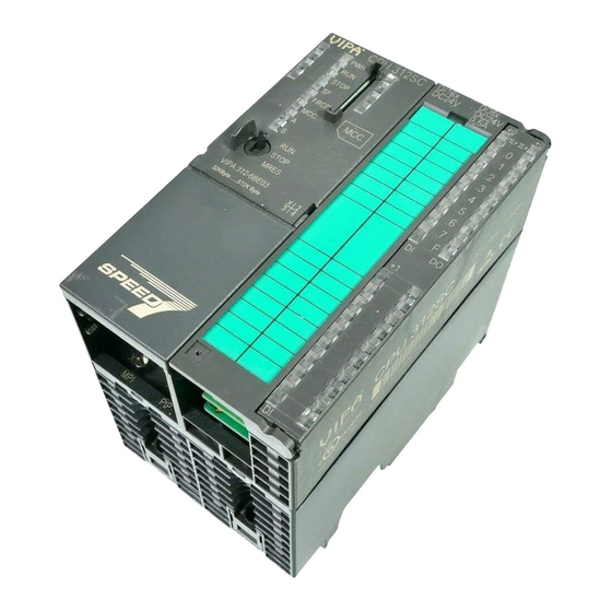
VIPA System 300S Hardware description Structure > General 4.2 Structure 4.2.1 General CPU 313-6CF13 1 LEDs of the integrated PROFIBUS DP master 2 LEDs of the CPU part 3 Storage media slot (lockable) 4 LEDs of the I/O part 5 Operating mode switch CPU... -
Page 26: Interfaces
Hardware description VIPA System 300S Structure > Interfaces 4.2.2 Interfaces X1: Power supply The CPU has an integrated power supply: The power supply has to be provided with DC 24V. For this serves the double DC 24V slot, that is underneath the flap. - Page 27 VIPA System 300S Hardware description Structure > Interfaces PROFIBUS functionality – Using the PROFIBUS functionality the integrated PROFIBUS DP master is connected to PROFIBUS via RS485 interface. – At master operation there is access to up to 124 DP slaves.
-
Page 28: In-/Output Area Cpu 313-6Cf13
Hardware description VIPA System 300S Structure > In-/Output area CPU 313-6CF13 4.2.3 In-/Output area CPU 313-6CF13 Overview The CPU 313-6CF13 has the following digital in- and output ranges integrated in one casing: Digital Input: 16xDC 24V, with interrupt capability Digital Output: 16xDC 24V, 0.5A... - Page 29 VIPA System 300S Hardware description Structure > In-/Output area CPU 313-6CF13 Pin assignment X11: DI Assignment 1L+ Power supply +DC 24V I+0.0 / Channel 0 (A) / Pulse I+0.1 / Channel 0 (B) / Direction I+0.2 / Channel 0 HW gate I+0.3 / Channel 1 (A) / Pulse...
- Page 30 Hardware description VIPA System 300S Structure > In-/Output area CPU 313-6CF13 Status indication X11: DI – LED (green) Supply voltage available for DI .0 ..7 – LEDs (green) I+0.0 ... I+0.7 I+1.0 ... I+1.7 Starting with ca. 15V the signal "1" at the input is recognized...
-
Page 31: Memory Management
As external storage medium for applications and firmware you may use a MMC storage module (Multimedia card). The VIPA storage media are pre-formatted with the PC format FAT16 and can be accessed via a card reader. After PowerON respectively an overall reset the CPU checks, if there is a storage medium with data valid for the CPU. -
Page 32: Battery Backup For Clock And Ram
Hardware description VIPA System 300S Structure > Operating mode switch CAUTION! If the media was already unlocked by the spring mecha- nism, with shifting the sliding mechanism, a just installed memory card can jump out of the slot! 4.2.6 Battery backup for clock and RAM A rechargeable battery is installed on every CPU to safeguard the contents of the RAM when power is removed. -
Page 33: Leds
VIPA System 300S Hardware description Structure > LEDs 4.2.8 LEDs LEDs CPU As soon as the CPU is supplied with 5V, the green PW-LED (Power) is on. Meaning (RUN) (STOP) (SFAIL) (FRCE) (MMC) green yellow yellow yellow Boot-up after PowerON ●... - Page 34 Hardware description VIPA System 300S Structure > LEDs Meaning (RUN) (STOP) (SFAIL) (FRCE) (MMC) ○ * Blinking with 10Hz: Error during Firmware update. on: ● | off: ○ | blinking (2Hz): BB | not relevant: X LEDs Ethernet PG/OP channel L/A, S The green L/A-LED (Link/Activity) indicates the physical connection of the Ethernet PG/OP channel to Ethernet.
-
Page 35: Technical Data
VIPA System 300S Hardware description Technical data Meaning (RUN) (ERR) ○ ● ○ ● Waiting state for start command from CPU. on: ● | off: ○ | blinking (2Hz): BB Slave operation Meaning (RUN) (ERR) green green ○ ○ ○... - Page 36 Hardware description VIPA System 300S Technical data Order no. 313-6CF13 Technical data digital inputs Number of inputs Cable length, shielded 1000 m Cable length, unshielded 600 m Rated load voltage DC 24 V Reverse polarity protection of rated load ü...
- Page 37 VIPA System 300S Hardware description Technical data Order no. 313-6CF13 Total current per group, vertical configuration Output voltage signal "1" at min. current L+ (-0.8 V) Output voltage signal "1" at max. current L+ (-0.8 V) Output current at signal "1", rated value 0.5 A...
- Page 38 Hardware description VIPA System 300S Technical data Order no. 313-6CF13 Operational limit of voltage ranges with SFU Basic error limit voltage ranges Basic error limit voltage ranges with SFU Destruction limit current Current inputs Max. input resistance (current range) Input current ranges...
- Page 39 VIPA System 300S Hardware description Technical data Order no. 313-6CF13 Basic error limit thermoelement ranges with Destruction limit thermocouple inputs Programmable temperature compensation External temperature compensation Internal temperature compensation Technical unit of temperature measurement Resolution in bit Measurement principle Basic conversion time...
- Page 40 Hardware description VIPA System 300S Technical data Order no. 313-6CF13 Destruction limit against external applied voltage Settling time for ohmic load Settling time for capacitive load Settling time for inductive load Resolution in bit Conversion time Substitute value can be applied...
- Page 41 VIPA System 300S Hardware description Technical data Order no. 313-6CF13 Operable communication modules PtP Operable communication modules LAN Status information, alarms, diagnostics Status display Interrupts Process alarm Diagnostic interrupt Diagnostic functions Diagnostics information read-out possible Supply voltage display green LED...
- Page 42 Hardware description VIPA System 300S Technical data Order no. 313-6CF13 Number of flags 8192 Byte Number of data blocks 4095 Max. data blocks size 64 KB Max. local data size per execution level 510 Byte Blocks Number of OBs Number of FBs...
- Page 43 VIPA System 300S Hardware description Technical data Order no. 313-6CF13 Communication functions PG/OP channel ü Global data communication ü Number of GD circuits, max. Size of GD packets, max. 22 Byte S7 basic communication ü S7 basic communication, user data per job...
- Page 44 Hardware description VIPA System 300S Technical data Order no. 313-6CF13 DP slave Point-to-point interface ü Functionality MPI Number of connections, max. PG/OP channel ü Routing ü Global data communication ü S7 basic communication ü S7 communication ü S7 communication as server ü...
- Page 45 VIPA System 300S Hardware description Technical data Order no. 313-6CF13 S7 communication as client Direct data exchange (slave-to-slave communi- cation) DPV1 ü Transmission speed, min. 9.6 kbit/s Transmission speed, max. 12 Mbit/s Automatic detection of transmission speed Transfer memory inputs, max.
- Page 46 Hardware description VIPA System 300S Technical data Order no. 313-6CF13 Number of connections, max. Productive connections Housing Material Mounting Rail System 300 Mechanical data Dimensions (WxHxD) 80 mm x 125 mm x 120 mm Weight 420 g Environmental conditions Operating temperature 0 °C to 60 °C...
-
Page 47: Deployment Cpu 313-6Cf13
VIPA System 300S Deployment CPU 313-6CF13 Start-up behavior Deployment CPU 313-6CF13 5.1 Assembly Ä Chapter 3 Information about assembly and cabling: ‘Assembly and installation guidelines’ on page 16 5.2 Start-up behavior Turn on power supply After the power supply has been switched on, the CPU changes to the operating mode the operating mode lever shows. -
Page 48: Addressing
Deployment CPU 313-6CF13 VIPA System 300S Addressing > Addressing Backplane bus I/O devices 5.3 Addressing 5.3.1 Overview To provide specific addressing of the installed peripheral modules, certain addresses must be allocated in the CPU. At the start-up of the CPU, this assigns automatically peripheral addresses for digital in-/ output modules starting with 0 and ascending depending on the slot location. -
Page 49: Address Assignment
VIPA System 300S Deployment CPU 313-6CF13 Address assignment DIOs: Start address = 4×(slot -4) AIOs, FMs, CPs: Start address = 16×(slot -4)+256 Example for automatic The following sample shows the functionality of the automatic address allocation address allocation: 5.4 Address assignment... -
Page 50: Hardware Configuration - Cpu
MOD, +R, -R, *R, /R) the content of ACCU 3 and ACCU 4 is loaded into ACCU 3 and 2. This may cause conflicts in applications that presume an unmodified ACCU 2. For more information may be found in the manual "VIPA Operation list SPEED7" at "Differences between SPEED7 and 300V programming". -
Page 51: Hardware Configuration - I/O Modules
VIPA System 300S Deployment CPU 313-6CF13 Hardware configuration - Ethernet PG/OP channel 5.6 Hardware configuration - I/O modules Hardware configuration After the hardware configuration place the System 300 modules in the of the modules plugged sequence starting with slot 4. - Page 52 Deployment CPU 313-6CF13 VIPA System 300S Hardware configuration - Ethernet PG/OP channel Switch on the power supply. ð After a short boot time the CP is ready for communication. He possibly has no IP address data and requires an initiali- zation.
-
Page 53: Cpu Parametrization
VIPA System 300S Deployment CPU 313-6CF13 CPU parametrization > CPU parameters Open the property window via double-click on the CP 343-1EX11 and enter for the CP at ‘Properties’ the IP address data, which you have assigned before. Assign the CP to a ‘Subnet’ . Without assignment the IP address data are not used! Transfer your project. - Page 54 Deployment CPU 313-6CF13 VIPA System 300S CPU parametrization > CPU parameters General Short description: The short description of the Siemens CPU 313-6CF03 is CPU 313C-2DP. Order No. / Firmware: Order number and firmware are identical to the details in the "hardware catalog"...
- Page 55 The preset reaction of the CPU may be changed to an I/O access error that occurs during the update of the process image by the system. The VIPA CPU is preset such that OB 85 is not called if an I/O access error occurs and no entry is made in the diagnostic buffer either.
-
Page 56: Setting Vipa Specific Cpu Parameters
CPU) Token Watch Requirements Since the VIPA specific CPU parameters may be set, the installation of the SPEEDBUS.GSD from VIPA in the hardware catalog is neces- sary. The CPU may be configured in a PROFIBUS master system and the appropriate parameters may be set after installation. - Page 57 (default) SPEEDBUS.GSG german SPEEDBUS.GSE english The GSD files may be found at www.vipa.com at the "Service" part. The integration of the SPEEDBUS.GSD takes place with the following proceeding: Browse to www.vipa.com Click to ‘Service è Download è GSD- and EDS-Files è...
-
Page 58: Vipa Specific Parameters
"DP-Master". Connect the slave system "VIPA_SPEEDbus". After installing the SPEEDBUS.GSD this may be found in the hardware catalog at Profibus-DP / Additional field devices / I/O / VIPA / VIPA_SPEEDBUS. For the slave system set the PROFIBUS address 100. - Page 59 PROFIBUS DP SyncOut In this operating mode the cycle time of the VIPA DP master system depends on the CPU cycle time. After CPU start-up the DP master gets synchronized. As soon as their cycle is passed they wait for the next synchronization impulse with output data of the CPU.
-
Page 60: Project Transfer
In the operating mode PROFIBUS DP SyncIn the CPU cycle is synchronized to the cycle of the VIPA PROFIBUS DP master system. Here the CPU cycle depends on the VIPA DP master with the longest cycle time. If the CPU gets into RUN it is synchronized with each PROFIBUS DP master. - Page 61 Please consider with the CPU 313-6CF13 that the total exten- sion of the MPI net does not exceed 50m. Per default the MPI net runs with 187.5kbaud. VIPA CPUs are delivered with MPI address 2. MPI programming cable The MPI programming cables are available at VIPA in different var- iants.
-
Page 62: Transfer Via Ethernet
Switch to the register Local connection. Set the COM port of the PCs and the transfer rate 38400baud for the MPI programming cable from VIPA. Transfer your project via ‘PLC è Load to module’ via PROFIBUS to the CPU and save it with ‘PLC è... -
Page 63: Transfer Via Mmc
CPU. To monitor the diagnosis entries, you select ‘PLC è Module Information’ in the Siemens SIMATIC Manager. Via the register "Diagnostic Buffer" you reach the diagnosis window. Ä Chapter 5.20 ‘VIPA specific diag- Information about the event IDs nostic entries’ on page 79. -
Page 64: Access To The Internal Web Page
The access takes place via the IP address of the Ethernet PG/OP channel. The web page only serves for information output. The moni- tored values are not alterable. CPU with Ethernet-PG/OP Slot 100 VIPA 313-6CF13 V..Px000137.pkg, Order no., firmware vers., package, serial no. SERIALNUMBER 02119 SUPPORTDATA : Information for support PRODUCT V3118, HARDWARE ... - Page 65 VIPA System 300S Deployment CPU 313-6CF13 Access to the internal Web page Slot 201 CPU component: DP master VIPA 342-1DA70 V3.3.0 Px000064.pkg Name, firmware-version, package SUPPORTDATA : Information for support PRODUCT V3300, BB000218 V5300, AB000068 V4170, ModuleType CB2C0010 Cycletime [microseconds] : min=17000 cur=17000...
-
Page 66: Operating Modes
Deployment CPU 313-6CF13 VIPA System 300S Operating modes > Overview 5.12 Operating modes 5.12.1 Overview The CPU can be in one of 4 operating modes: Operating mode STOP Operating mode START-UP Operating mode RUN Operating mode HALT Certain conditions in the operating modes START-UP and RUN require a specific reaction from the system program. - Page 67 VIPA System 300S Deployment CPU 313-6CF13 Operating modes > Overview Testing in single step mode is possible with STL. If necessary switch the view via ‘View è STL’ to STL. The block must be opened online and must not be protected.
-
Page 68: Function Security
(parametrizable min. 1ms) that stop res. execute a RESET at the CPU in case of an error and set it into a defined STOP state. The VIPA CPUs are developed function secure and have the following system properties:... - Page 69 VIPA System 300S Deployment CPU 313-6CF13 Overall reset Overall reset by means Precondition of the operating mode The operating mode of the CPU is to be switched to STOP. For switch this switch the operating mode switch of the CPU to "STOP".
-
Page 70: Firmware Update
Latest firmware at The latest firmware versions are to be found in the service area at www.vipa.com www.vipa.com. For example the following files are necessary for the firmware update of the CPU 313-6CF13 and its components with hardware release 1: 313-6CF13, Hardware release 1: Px000137.pkg... - Page 71 Via the register ‘General’ the window with hardware and firm- ware version may be selected. ð Due to software-technical reasons there is something dif- ferent of the VIPA CPU 313-6CF13 to the CPU 313C-2DP from Siemens: 1 VIPA order number (VIPA 313-6CF13)
- Page 72 Deployment CPU 313-6CF13 VIPA System 300S Firmware update CAUTION! With a firmware update an overall reset is automatically executed. If your program is only available in the load memory of the CPU it is deleted! Save your program before executing a firmware update! After the firmware update you should execute a "Set back to factory set-...
-
Page 73: Reset To Factory Setting
VIPA System 300S Deployment CPU 313-6CF13 Slot for storage media 5.15 Reset to factory setting Proceeding With the following proceeding the internal RAM of the CPU is com- pletely deleted and the CPU is reset to delivery state. Please note that here also the IP address of the Ethernet PG/OP channel is set to 0.0.0.0 and the MPI address is reset to the address... -
Page 74: Memory Extension With Mcc
Overview There is the possibility to extend the work memory of the CPU. For this, a MCC memory extension card is available from VIPA. The MCC is a specially prepared MMC (Multimedia Card). By plugging the MCC into the MCC slot and then an overall reset the according memory expansion is released. -
Page 75: Extended Know-How Protection
Extended know-how protection Overview Besides the "standard" Know-how protection the SPEED7-CPUs from VIPA provide an "extended" know-how protection that serves a secure block protection for accesses of 3. persons. Standard protection The standard protection from Siemens transfers also protected blocks to the PG but their content is not displayed. - Page 76 Deployment CPU 313-6CF13 VIPA System 300S Extended know-how protection Protect blocks with pro- Create a new wld-file in your project engineering tool with ‘File tect.wld è Memory Card file è New’ and rename it to "protect.wld". Transfer the according blocks into the file by dragging them with the mouse from the project to the file window of protect.wld.
-
Page 77: Mmc-Cmd - Auto Commands
VIPA System 300S Deployment CPU 313-6CF13 MMC-Cmd - Auto commands Usage of protected Due to the fact that reading of a "protected" block from the CPU moni- blocks tors no symbol labels it is convenient to provide the "block covers" for the end user. - Page 78 Deployment CPU 313-6CF13 VIPA System 300S MMC-Cmd - Auto commands Command Description Diagnostics entry SET_NETWORK IP parameters for Ethernet PG/OP channel may 0xE80E be set by means of this command. The IP parameters are to be given in the order IP address, subnet mask and gateway in the format x.x.x.x each separated by a comma.
-
Page 79: Vipa Specific Diagnostic Entries
You may read the diagnostic buffer of the CPU via the Siemens nostic buffer SIMATIC Manager. Besides of the standard entries in the diagnostic buffer, the VIPA CPUs support some additional specific entries in form of event-IDs. The current content of the diagnostics buffer is stored at the memory card by means of the CMD DIAGBUFF. - Page 80 0xE004 Multiple parametrization of a periphery address ZInfo1: Periphery address ZInfo2: Slot 0xE005 Internal error - Please contact the VIPA Hotline! 0xE006 Internal error - Please contact the VIPA Hotline! 0xE007 Configured in-/output bytes do not fit into periphery area...
- Page 81 VIPA System 300S Deployment CPU 313-6CF13 VIPA specific diagnostic entries Event-ID Description 0xE0CC Communication error MPI / Serial ZInfo1: Code 1: Wrong priority 2: Buffer overflow 3: Frame format error 4: Wrong SSL request (SSL-ID not valid) 5: Wrong SSL request (SSL-SubID not valid)
- Page 82 ZInfo1: Periphery address ZInfo3: 0: Periphery address is input, 1: Periphery address is output 0xE701 Internal error - Please contact the VIPA Hotline! 0xE703 Internal error - Please contact the VIPA Hotline! 0xE720 Internal error - Please contact the VIPA Hotline!
- Page 83 CMD - Auto command: Error: Error while reading CMD file (memory card error) 0xE901 Check sum error 0xEA00 Internal error - Please contact the VIPA Hotline! 0xEA01 Internal error - Please contact the VIPA Hotline! 0xEA02 SBUS: Internal error (internal plugged sub module not recognized)
- Page 84 ZInfo1: Periphery address ZInfo2: Slot ZInfo3: Data width 0xEA15 Internal error - Please contact the VIPA Hotline! 0xEA18 SBUS: Error at mapping of the master periphery ZInfo2: Slot of the master 0xEA19 Internal error - Please contact the VIPA Hotline!
- Page 85 Error - PROFINET IO controller reports multiple parametrization of a periphery address ZInfo1: Periphery address ZInfo2: User slot of the PROFINET I/O controller ZInfo3: Data width 0xEA61 ... 0xEA63 Internal error - Please contact the VIPA Hotline! 0xEA64 PROFINET/EtherCAT CP Configuration error: Zinfo1: Bit 0: Too many devices...
- Page 86 OBNo: PROFINET IO controller slot DatId: Device-No. ZInfo1: Record set number ZInfo2: Record set handle ZInfo3: Internal error code for service purposes 0xEA69 Internal error - Please contact the VIPA Hotline! 0xEA6A PROFINET IO controller Service error in communication stack PK: Rackslot OBNo: ServiceIdentifier DatId: 0 ZInfo1: ServiceError.Code...
- Page 87 VIPA System 300S Deployment CPU 313-6CF13 VIPA specific diagnostic entries Event-ID Description 0xEA6B PROFINET IO controller Vendor ID mismatch PK: Rackslot OBNo: PLC Mode DatId: 0 ZInfo1: Device ID ZInfo2: - ZInfo3: - 0xEA6C PROFINET IO controller Device ID mismatch...
- Page 88 Deployment CPU 313-6CF13 VIPA System 300S VIPA specific diagnostic entries Event-ID Description 0xEA6F PROFINET IO controller PN module mismatch PK: Rackslot OBNo: PLC-Mode DatId: 0 ZInfo1: Device ID ZInfo2: - ZInfo3: - 0xEA97 Storage error SBUS service channel ZInfo3 = Slot...
- Page 89 VIPA System 300S Deployment CPU 313-6CF13 VIPA specific diagnostic entries Event-ID Description 0xEB20 SLIO error: Interrupt information undefined 0xEB21 SLIO error on accessing the configuration data 0xEC03 EtherCAT: Configuration error ZInfo1: Errorcode 1: NUMBER_OF_SLAVES_NOT_SUPPORTED 2: SYSTEM_IO_NR_INVALID 3: INDEX_FROM_SLOT_ERROR 4: MASTER_CONFIG_INVALID...
- Page 90 Deployment CPU 313-6CF13 VIPA System 300S VIPA specific diagnostic entries Event-ID Description 0xEC11 EtherCAT: Restoration bus with missing slaves OB start Info (Local data) StartEvent and Eventclass: 0xEC11 DatID: 0xXXYY: XX=0x54 with input address in ZInfo1, XX=0x55 with output address.
- Page 91 VIPA System 300S Deployment CPU 313-6CF13 VIPA specific diagnostic entries Event-ID Description 0xED12 EtherCAT: Failure slave OB start Info (Local data) StartEvent and Eventclass: 0xED12 DatID: 0xXXYY: XX=0x54 with input address in ZInfo1, XX=0x55 with output address. YY=0x00 Station not available,...
- Page 92 EtherCAT: Interrupt Queue Overflow OB start Info (Local data) StartEvent and Eventclass: 0xED31 ZInfo2: Diagnostics address of the master 0xED40 ... 0xED4F Internal error - Please contact the VIPA Hotline! 0xED50 EtherCAT: DC not in Sync ZInfo1: Diagnostics address of the master...
- Page 93 Internal error - Please contact the VIPA Hotline! 0xEEEE CPU was completely overall reset, since after PowerON the start-up could not be finished. 0xEF11 ... 0xEF13 Internal error - Please contact the VIPA Hotline! HB140 | CPU-SC | 313-6CF13 | GB | 15-50...
-
Page 94: Control And Monitoring Of Variables With Test Functions
VIPA System 300S Control and monitoring of variables with test functions Event-ID Description 0xEFFF Internal error - Please contact the VIPA Hotline! PK: C-Source module number | DatID: Line number 5.21 Control and monitoring of variables with test functions Overview... - Page 95 VIPA System 300S Deployment CPU 313-6CF13 Control and monitoring of variables with test functions Control of outputs – It is possible to check the wiring and proper operation of output modules. – You can set outputs to any desired status with or without a control program.
-
Page 96: Deployment I/O Periphery
Deployment I/O periphery VIPA System 300S Overview Deployment I/O periphery 6.1 Overview Hardware At the 313-6CF13 the connectors for digital in-/output and technolog- ical functions are integrated to a 2tier casing. Project engineering The project engineering takes place in the Siemens SIMATIC man- ager as CPU 313C-2DP from Siemens (6ES7 313-6CF03-0AB0 V2.6). -
Page 97: In-/Output Area Cpu 313-6Cf13
VIPA System 300S Deployment I/O periphery In-/Output area CPU 313-6CF13 6.2 In-/Output area CPU 313-6CF13 Overview The CPU 313-6CF13 has the following digital in- and output ranges integrated in one casing: Digital Input: 16xDC 24V, with interrupt capability Digital Output: 16xDC 24V, 0.5A... - Page 98 Deployment I/O periphery VIPA System 300S In-/Output area CPU 313-6CF13 Pin assignment X11: DI Assignment 1L+ Power supply +DC 24V I+0.0 / Channel 0 (A) / Pulse I+0.1 / Channel 0 (B) / Direction I+0.2 / Channel 0 HW gate I+0.3 / Channel 1 (A) / Pulse...
- Page 99 VIPA System 300S Deployment I/O periphery In-/Output area CPU 313-6CF13 Status indication X11: DI – LED (green) Supply voltage available for DI .0 ..7 – LEDs (green) I+0.0 ... I+0.7 I+1.0 ... I+1.7 Starting with ca. 15V the signal "1" at the input is recognized...
-
Page 100: Address Assignment
Deployment I/O periphery VIPA System 300S Address assignment Status indication X11: DO 2L+, 3L+ – LED (green) Supply voltage available for DO .0 ..7 – LEDs (green) Q+0.0 ... Q+0.7 Q+1.0 ... Q+1.7 The according LED is on at active output –... -
Page 101: Digital Part
VIPA System 300S Deployment I/O periphery Digital part 6.4 Digital part 313-6CF13 The digital part consists of 16 input, 16 output and 3 channels for technological functions. Each of these digital input- respectively output channels shows its state via a LED. By means of the parame- terization you may assign interrupt properties to the inputs I+0.0 to... - Page 102 Deployment I/O periphery VIPA System 300S Digital part Status indication X11: DI – LED (green) Supply voltage available for DI .0 ..7 – LEDs (green) I+0.0 ... I+0.7 I+1.0 ... I+1.7 Starting with ca. 15V the signal "1" at the input is recognized...
-
Page 103: Access To The I/O Area
VIPA System 300S Deployment I/O periphery Digital part > Access to the I/O area Status indication X11: DO 2L+, 3L+ – LED (green) Supply voltage available for DO .0 ..7 – LEDs (green) Q+0.0 ... Q+0.7 Q+1.0 ... Q+1.7 The according LED is on at active output –... -
Page 104: Parameterization - Digital Part
Deployment I/O periphery VIPA System 300S Counter > Counter - Fast introduction Sub module Default address Access Assignment DWort reserved DWort reserved 6.4.2 Parameterization - Digital part Parameter data Parameters of the digital part may be set by means of the DI16/DO16 submodule of the CPU 313C-2DP from Siemens during hardware configuration. - Page 105 VIPA System 300S Deployment I/O periphery Counter > Counter - Fast introduction Independent of the number of activated counters for the CPU 313-6CF13 the maximum frequency amounts to 30kHz. The controlling of the appropriate modes of operation is made from the user program by the SFB COUNT (SFB 47).
- Page 106 Deployment I/O periphery VIPA System 300S Counter > Counter - Fast introduction Controlling the counter The counter is controlled by the internal gate (i gate). The i gate is the result of logic operation of hardware gate (HW gate) and software gate (SW gate), where the HW gate evaluation may be deactivated by the parameterization.
- Page 107 VIPA System 300S Deployment I/O periphery Counter > Counter - Fast introduction Count value £ comparison value: Output is set as long as counter value £ comparison value. Pulse at comparison value: You can specify a pulse period for adaptation to the actuators you are using. The output is set for the given pulse duration, as soon as the counter reached the compar- ison value.
- Page 108 Deployment I/O periphery VIPA System 300S Counter > Counter - Fast introduction Parameters Description Range of values Default Gate function Cancel count: The count starts Abort the Cancel count when the gate opens and count opera- resumes at the load value when tion the gate opens again.
-
Page 109: Sfb 47 - Count - Counter Controlling
6.5.2 SFB 47 - COUNT - Counter controlling Description The SFB 47 is a specially developed block for the VIPA CPU for con- trolling of the counters. The SFB is to be called with the corre- sponding instance DB. Here the parameters of the SFB are stored. - Page 110 Deployment I/O periphery VIPA System 300S Counter > SFB 47 - COUNT - Counter controlling Parameters Name Data type Address Default Comment value (Instance LADDR WORD 300h This parameter is not evaluated. Always the internal I/O periphery is addressed. CHANNEL...
- Page 111 VIPA System 300S Deployment I/O periphery Counter > SFB 47 - COUNT - Counter controlling Local data only in instance DB Name Data type Address Default Comment value (Instance RES00 BOOL 26.0 FALSE reserved RES01 BOOL 26.1 FALSE reserved RES02 BOOL 26.2...
- Page 112 Deployment I/O periphery VIPA System 300S Counter > SFB 47 - COUNT - Counter controlling Proceeding The deployment of the request interface takes place at the following sequence: Edit the following input parameters: Name Data type Address (DB) Default Comment...
- Page 113 VIPA System 300S Deployment I/O periphery Counter > SFB 47 - COUNT - Counter controlling A new job may be started with JOB_DONE = TRUE. A value to be read of a read job may be found in JOB_OVAL in the instance DB at address 28.
-
Page 114: Counter - Functions
Deployment I/O periphery VIPA System 300S Counter > Counter - Functions Valid range Writing hysteresis 0 ... 255 Writing pulse duration* 0 ... 510ms *) Only even values allowed. Odd values are automatically rounded. Latch function As soon as during a count process an edge 0-1 is recognized at the "Latch"... - Page 115 VIPA System 300S Deployment I/O periphery Counter > Counter - Functions The count process starts after closing and restart of the gate begin- ning with the load value. Interrupt count process The count process continuous after closing and restart of the gate beginning with the last recent counter value.
- Page 116 Deployment I/O periphery VIPA System 300S Counter > Counter - Functions Limits Valid value range Lower count limit -2 147 483 648 (-2 Upper count limit +2 147 483 647 (2 Interrupting gate control: Aborting gate control: Main counting direction forward The counter counts starting with the load value.
- Page 117 VIPA System 300S Deployment I/O periphery Counter > Counter - Functions Main counting direction backwards The counter counts backwards starting with the load value. When the counter reaches the end value +1 in negative direction, it jumps to the load value at the next negative count pulse and the gate is automatically closed.
- Page 118 Deployment I/O periphery VIPA System 300S Counter > Counter - Functions Limits Valid value range Lower count limit -2 147 483 648 (-2 Upper count limit +2 147 483 647 (2 Main counting direction forward The counter counts forward starting with the load value.
-
Page 119: Counter - Additional Functions
VIPA System 300S Deployment I/O periphery Counter > Counter - Additional functions Limits Valid value range Limit value -2 147 483 648 (-2 to +2 147 483 646 (2 Upper count limit +2 147 483 647 (2 6.5.4 Counter - Additional functions... - Page 120 Deployment I/O periphery VIPA System 300S Counter > Counter - Additional functions Gate function The counter is controlled by the internal gate (i gate). The i gate is the result of logic operation of hardware gate (HW gate) and software gate (SW gate), where the HW gate evaluation may be deactivated by the parameterization.
- Page 121 VIPA System 300S Deployment I/O periphery Counter > Counter - Additional functions At stop function, the counter continues counting with the last recent counter value after gate restart. Gate control abort, How the CPU should react at opening of the SW gate may be set with interruption the parameter Gate function.
- Page 122 Deployment I/O periphery VIPA System 300S Counter > Counter - Additional functions Gate control via SW/HW gate, canceling (HW gate activated, gate function: Cancel count) SW gate HW gate Reaction Counter edge 0-1 Continue edge 0-1 Restart with load value...
- Page 123 VIPA System 300S Deployment I/O periphery Counter > Counter - Additional functions Characteristics of the You pre-define the behavior of the counter output via the parameteri- output zation: No comparison The output is set as normal output. The SFB input parameter CTRL_DO is effect less.
- Page 124 Deployment I/O periphery VIPA System 300S Counter > Counter - Additional functions ³ Effect at counter value comparison value 1 Counter value ³ comparison value ® output is set and hysteresis activated 2 Leave hysteresis range ® output is reset 3 Counter value ³...
- Page 125 VIPA System 300S Deployment I/O periphery Counter > Counter - Additional functions 1 Counter value = comparison value ® output is set and hysteresis activated 2 Leave hysteresis range ® output is reset and counter value < comparison value 3 Counter value = comparison value ® output is set and hysteresis activated 4 Output is reset for leaving hysteresis range and counter value >...
-
Page 126: Frequency Measurement
Deployment I/O periphery VIPA System 300S Frequency measurement > Overview With reaching the comparison condition the hysteresis gets active and a pulse of the parameterized duration is put out. As long as the counter value is within the hysteresis range, no other pulse is put out. -
Page 127: Inputs For The Frequency Measurement
VIPA System 300S Deployment I/O periphery Frequency measurement > Inputs for the frequency measurement During frequency measurement the count function at the same channel is deactivated. 6.6.2 Inputs for the frequency measurement For frequency measurement, connect your signal to be measured at input B. -
Page 128: Parameterization
Deployment I/O periphery VIPA System 300S Frequency measurement > Parameterization Status indication X11: DI – LED (green) Supply voltage available for DI .0 ..7 – LEDs (green) I+0.0 ... I+0.7 I+1.0 ... I+1.7 Starting with ca. 15V the signal "1" at the input is recognized and the according LED is activated 6.6.3 Parameterization... -
Page 129: Sfb 48 - Frequenc - Frequency Measurement
VIPA System 300S Deployment I/O periphery Frequency measurement > SFB 48 - FREQUENC - Frequency measurement Basic parameters Here the interrupts, the counter component should trigger, may be selected. You have the following options: – None: There is no interrupt triggered. - Page 130 Deployment I/O periphery VIPA System 300S Frequency measurement > SFB 48 - FREQUENC - Frequency measurement Name Declaration Data type Address Default Comment value (Inst.-DB) SW_GATE INPUT BOOL FALSE Enables the Software gate JOB_REQ INPUT BOOL FALSE Initiates the job (edge 0-1)
- Page 131 VIPA System 300S Deployment I/O periphery Frequency measurement > SFB 48 - FREQUENC - Frequency measurement Edit the following input parameters: Name Data type Address Default Comment (DB) JOB_REQ BOOL FALSE Initiates the job (edges 0-1) JOB_ID WORD Job ID:...
-
Page 132: Pulse Width Modulation - Pwm
Deployment I/O periphery VIPA System 300S Pulse width modulation - PWM > Overview open (activate): In the user program by setting SW_GATE of SFB 48 close (deactivate): In the user program by resetting SW_GATE of SFB 48 6.7 Pulse width modulation - PWM 6.7.1 Overview... - Page 133 VIPA System 300S Deployment I/O periphery Pulse width modulation - PWM > Overview Pin assignment X11: DO Assignment 2L+ Power supply +DC 24V O+0.0 / Channel 0 Output O+0.1 / Channel 1 Output Q+0.2 / Channel 2 Output Q+0.3 Q+0.4 Q+0.5...
-
Page 134: Parameterization
Deployment I/O periphery VIPA System 300S Pulse width modulation - PWM > Parameterization 6.7.2 Parameterization Start the Siemens SIMATIC Manager with your project and open the hardware configurator. Place a profile rail. Configure at slot 2 the Siemens CPU 313C-2DP (6ES7 313-6CF03-0AB0 V2.6). - Page 135 VIPA System 300S Deployment I/O periphery Pulse width modulation - PWM > Parameterization 1 Period duration 2 ON delay 3 Pulse duration 4 Pulse pause Output format Here select the range of values of the output value. With this the...
-
Page 136: Sfb 49 - Pulse - Pulse Width Modulation
Deployment I/O periphery VIPA System 300S Pulse width modulation - PWM > SFB 49 - PULSE - Pulse width modulation 6.7.3 SFB 49 - PULSE - Pulse width modulation Description The SFB 49 is a specially developed block for the CPU 31xSC for pulse width modulation The SFB PULSE should cyclically be called (e.g. - Page 137 VIPA System 300S Deployment I/O periphery Pulse width modulation - PWM > SFB 49 - PULSE - Pulse width modulation Local data only in Instance DB Name Data type Address Default Comment (Instance DB) JOB_OVAL DINT 20.0 Output value for read request.
- Page 138 Deployment I/O periphery VIPA System 300S Pulse width modulation - PWM > SFB 49 - PULSE - Pulse width modulation Call the SFB. The job is processed immediately. JOB_DONE only applies to SFB run with the result FALSE. JOB_ERR = TRUE if an error occurred.
-
Page 139: Diagnostic And Interrupt
VIPA System 300S Deployment I/O periphery Diagnostic and interrupt > Process interrupt 6.8 Diagnostic and interrupt Overview The parameterization allows you to define the following trigger for a hardware interrupt that may initialize a diagnostic interrupt: Counter function Edge at a digital input... - Page 140 Deployment I/O periphery VIPA System 300S Diagnostic and interrupt > Process interrupt Local Bit 7...0 byte Bit 0: Gate counter 0 open (activated) Bit 1: Gate counter 0 closed Bit 2: Over-/underflow/end value counter 0 Bit 3: Counter 0 reached comparison value...
-
Page 141: Diagnostic Interrupt
VIPA System 300S Deployment I/O periphery Diagnostic and interrupt > Diagnostic interrupt 6.8.2 Diagnostic interrupt Activation Please consider that diagnostic interrupts are enabled only if you have selected one of the technology functions (counting, frequency measurement, PWM) and set "Diag- nostics+Process interrupt"... - Page 142 Deployment I/O periphery VIPA System 300S Diagnostic and interrupt > Diagnostic interrupt tents of record set 0 are already in the local double word 8 when calling the OB 82. The SFC 59 allows you to also read the record set 1 that contains additional information.
- Page 143 VIPA System 300S Deployment I/O periphery Diagnostic and interrupt > Diagnostic interrupt Diagnostic record set 1 The record set 1 contains the 4byte of the record set 0 and addition- at counter function ally 12byte module specific diagnostic data. The diagnostic bytes...
- Page 144 Deployment I/O periphery VIPA System 300S Diagnostic and interrupt > Diagnostic interrupt Byte Bit 7...0 Diagnostic interrupt due to "process interrupt lost" at... Bit 0: ... input I+1.0 Bit 1: 0 (fix) Bit 2: ... input I+1.1 Bit 3: 0 (fix) Bit 4: ...
- Page 145 VIPA System 300S Deployment I/O periphery Diagnostic and interrupt > Diagnostic interrupt Diagnostic Record set 1 The record set 1 contains the 4byte of the record set 0 and addition- at frequency measure- ally 12byte module specific diagnostic data. The diagnostic bytes...
- Page 146 Deployment I/O periphery VIPA System 300S Diagnostic and interrupt > Diagnostic interrupt Byte Bit 7...0 Diagnostic interrupt due to "process interrupt lost" at... Bit 0: ... input I+1.0 Bit 1: 0 (fix) Bit 2: ... input I+1.1 Bit 3: 0 (fix) Bit 4: ...
- Page 147 VIPA System 300S Deployment I/O periphery Diagnostic and interrupt > Diagnostic interrupt Byte Bit 7...0 Ä ‘Record set 0 Diagnostic 0 ... 3 Content record set 0 ’ incoming on page 142 Bit 6 ... 0: Channel type (here 70h) –...
- Page 148 Deployment I/O periphery VIPA System 300S Diagnostic and interrupt > Diagnostic interrupt Byte Bit 7...0 Diagnostic interrupt due to "process interrupt lost" at... Bit 0: ... input I+1.4 Bit 1: 0 (fix) Bit 2: ... input I+1.5 Bit 3: 0 (fix) Bit 4: ...
-
Page 149: Deployment Ptp Communication
VIPA System 300S Deployment PtP communication Principle of the data transfer Deployment PtP communication 7.1 Fast introduction General Per default, the RS485 interface of the CPU is used for PROFIBUS DP master. Via hardware configuration the RS485 interface may be switched to point-to-point (PtP) communication via the Parameter Function RS485 X3 of the Properties. -
Page 150: Deployment Of Rs485 Interface For Ptp
Parameter Function RS485 X3 of the Properties. Requirements Since the VIPA specific CPU parameters may be set, the installation of the SPEEDBUS.GSD from VIPA in the hardware catalog is neces- sary. The CPU may be configured in a PROFIBUS master system and the appropriate parameters may be set after installation. - Page 151 (default) SPEEDBUS.GSG german SPEEDBUS.GSE english The GSD files may be found at www.vipa.com at the "Service" part. The integration of the SPEEDBUS.GSD takes place with the following proceeding: Browse to www.vipa.com Click to ‘Service è Download è GSD- and EDS-Files è...
- Page 152 "DP-Master". Connect the slave system "VIPA_SPEEDbus". After installing the SPEEDBUS.GSD this may be found in the hardware catalog at PROFIBUS DP / Additional field devices / I/O / VIPA / VIPA_SPEEDBUS. For the slave system set the PROFIBUS address 100.
-
Page 153: Parametrization
VIPA System 300S Deployment PtP communication Parametrization> FC/SFC 216 - SER_CFG RS485 9pin SubD jack RS485 n.c. M24V RxD/TxD-P (Line B) P24V RxD/TxD-N (Line A) n.c. Connection 7.4 Parametrization 7.4.1 FC/SFC 216 - SER_CFG Description The parametrization happens during runtime deploying the FC/SFC 216 (SER_CFG). - Page 154 Deployment PtP communication VIPA System 300S Parametrization> FC/SFC 216 - SER_CFG Parameters Parameter Declaration Data type Description PROTOCOL BYTE 1=ASCII, 2=STX/ETX, 3=3964R PARAMETER Pointer to protocol-parameters BAUDRATE BYTE Number of baudrate CHARLEN BYTE 0=5bit, 1=6bit, 2=7bit, 3=8bit PARITY BYTE 0=Non, 1=Odd, 2=Even...
- Page 155 VIPA System 300S Deployment PtP communication Parametrization> FC/SFC 216 - SER_CFG < 20, oth- The start res. end sign should always be a value erwise the sign is ignored! With not used IDs please always enter FFh! Data block at 3964R...
-
Page 156: Communication
809Ah Interface not found e. g. interface is used by PROFIBUS In the VIPA SLIO CPU with FeatureSet PTP_NO only the ASCII protocol is configurable. If another protocol is selected the FC/SFC216 also left with this error code. -
Page 157: Fc/Sfc 217 - Ser_Snd
VIPA System 300S Deployment PtP communication Communication> FC/SFC 217 - SER_SND 7.5.2 FC/SFC 217 - SER_SND Description This block sends data via the serial interface. The repeated call of the FC/SFC 217 SER_SND delivers a return value for 3964R, USS and Modbus via RETVAL that contains, among other things, recent infor- mation about the acknowledgement of the partner station. - Page 158 Deployment PtP communication VIPA System 300S Communication> FC/SFC 217 - SER_SND Error code Description 8x24h Error in FC/SFC parameter x, where x: 1: Error in DATAPTR 2: Error in DATALEN 8122h Error in parameter DATAPTR (e.g. DB too short) 807Fh...
- Page 159 VIPA System 300S Deployment PtP communication Communication> FC/SFC 217 - SER_SND Error code Description 80F0h Wrong checksum in respond 80FEh Wrong start sign in respond 80FFh Wrong slave address in respond 9000h Buffer overflow (no data send) 9001h Data too long (>1024byte) 9002h Data too short (<2byte)
- Page 160 Deployment PtP communication VIPA System 300S Communication> FC/SFC 217 - SER_SND Principles of program- The following text shortly illustrates the structure of programming a ming send command for the different protocols. 3964R HB140 | CPU-SC | 313-6CF13 | GB | 15-50...
- Page 161 VIPA System 300S Deployment PtP communication Communication> FC/SFC 217 - SER_SND USS / Modbus ASCII / STX/ETX HB140 | CPU-SC | 313-6CF13 | GB | 15-50...
-
Page 162: Fc/Sfc 218 - Ser_Rcv
Deployment PtP communication VIPA System 300S Communication> FC/SFC 218 - SER_RCV 7.5.3 FC/SFC 218 - SER_RCV Description This block receives data via the serial interface. Using the FC/SFC 218 SER_RCV after SER_SND with the protocols USS and Modbus the acknowledgement telegram can be read. - Page 163 VIPA System 300S Deployment PtP communication Communication> FC/SFC 218 - SER_RCV STX/ETX Error Description overflow The received telegram exceeds the size of the receive buffer. char A sign outside the range 20h ... 7Fh has been received. overflow Buffer is full.
-
Page 164: Protocols And Procedures
There is no reception acknowledgement. The communication procedure has to be controlled by the concerning user application. An according Receive_ASCII FB may be found within the VIPA library in the service area of www.vipa.com. STX/ETX STX/ETX is a simple protocol with start and end ID, where STX stands for Start of Text and ETX for End of Text. - Page 165 VIPA System 300S Deployment PtP communication Protocols and procedures Any data transferred from the periphery must be preceded by a Start followed by the data characters and the end character. Depending of the byte width the following ASCII characters can be transferred: 5bit: not allowed: 6bit: 20...3Fh, 7bit: 20...7Fh, 8bit:...
- Page 166 Deployment PtP communication VIPA System 300S Protocols and procedures 3964 The 3964R procedure controls the data transfer of a point-to-point link between the CPU and a communication partner. The procedure adds control characters to the message data during data transfer. These control characters may be used by the communication partner to verify the complete and error free receipt.
- Page 167 VIPA System 300S Deployment PtP communication Protocols and procedures It is essential: You may connect 1 master and max. 31 slaves at the bus The single slaves are addressed by the master via an address sign in the telegram. The communication happens exclusively in half-duplex operation.
-
Page 168: Modbus - Function Codes
Deployment PtP communication VIPA System 300S Modbus - Function codes After a request from the master, this waits for a preset delay time for an answer of the slave. During the delay time, communication with other slaves is not possible. - Page 169 0x and 1x gives you access to digital bit areas and 3x and 4x to analog word areas. For the CPs from VIPA is not differentiating digital and analog data, the following assignment is valid: 0x - Bit area for master output data...
- Page 170 Deployment PtP communication VIPA System 300S Modbus - Function codes The description always takes place from the point of view of the master. Here data, which were sent from master to slave, up to their target are designated as "output" data (OUT) and contrary slave data received by the master were designated as "input"...
- Page 171 VIPA System 300S Deployment PtP communication Modbus - Function codes Read n words 03h, 04h 03h: Read n words of master output area 4x 04h: Read n words master input area 3x Command telegram Slave address Function code Address 1. bit...
- Page 172 Deployment PtP communication VIPA System 300S Modbus - Function codes Write 1 word 06h Code 06h: Write 1 word to master output area 4x Command telegram Slave address Function code Address word Value word Check sum CRC/ 1byte 1byte 1word...
-
Page 173: Modbus - Example Communication
VIPA System 300S Deployment PtP communication Modbus - Example communication Write n words 10h Code 10h: Write n words to master output area 4x Command telegram Slave Func- Address Number Number Data 1. Data 2. Check address tion 1. word... - Page 174 Deployment PtP communication VIPA System 300S Modbus - Example communication Execute the project engineering of the slave! The PLC user application at the slave has the following structure: OB 100: Call SFC 216 (configuration as Modbus RTU slave) with timeout setting and Modbus address in the DB and error evaluation.
- Page 175 VIPA System 300S Deployment PtP communication Modbus - Example communication HB140 | CPU-SC | 313-6CF13 | GB | 15-50...
-
Page 176: Deployment Profibus Communication
Deployment PROFIBUS communication VIPA System 300S Fast introduction Deployment PROFIBUS communication 8.1 Overview PROFIBUS DP PROFIBUS is an international standard applicable to an open and serial field bus for building, manufacturing and process automa- tion that can be used to create a low (sensor-/actuator level) or medium (process level) performance network of programmable logic controllers. -
Page 177: Hardware Configuration - Cpu
MOD, +R, -R, *R, /R) the content of ACCU 3 and ACCU 4 is loaded into ACCU 3 and 2. This may cause conflicts in applications that presume an unmodified ACCU 2. For more information may be found in the manual "VIPA Operation list SPEED7" at "Differences between SPEED7 and 300V programming". -
Page 178: Deployment As Profibus Dp Master
Deployment PROFIBUS communication VIPA System 300S Deployment as PROFIBUS DP master 8.4 Deployment as PROFIBUS DP master Precondition The hardware configuration described before was established. Proceeding Open the properties dialog of the DP interface of the CPU by means of a double-click at ‘DP’ . -
Page 179: Deployment As Profibus Dp Slave
VIPA System 300S Deployment PROFIBUS communication Deployment as PROFIBUS DP slave 8.5 Deployment as PROFIBUS DP slave Fast introduction In the following the deployment of the PROFIBUS section as "intelli- gent" DP slave on master system is described, which exclusively may be configured in the Siemens SIMATIC Manager. - Page 180 Deployment PROFIBUS communication VIPA System 300S Deployment as PROFIBUS DP slave Open the properties dialog of the DP interface of the CPU by means of a double-click at ‘DP’ . Set Interface: type to "PROFIBUS". Connect to PROFIBUS and preset an address (e.g. 2) and con- firm with [OK].
-
Page 181: Profibus Installation Guidelines
VIPA System 300S Deployment PROFIBUS communication PROFIBUS installation guidelines For further configuration, install the GSD file from the appropri- ately configured Siemens slave CPU. Choose via ‘Additional field devices è PLC è SIMATIC’ the Siemens slave CPU. 10. Connect your slave system to the master system by dragging the slave CPU via PROFIBUS onto the master system. - Page 182 Deployment PROFIBUS communication VIPA System 300S PROFIBUS installation guidelines The PROFIBUS line has to be terminated with its ripple resistor. Please make sure to terminate the last partici- pants on the bus at both ends by activating the terminating resistor.
- Page 183 PROFIBUS cable type A (EN50170). Starting with release 5 you also can use highly flexible bus cable: Lapp Kabel order no: 2170222, 2170822, 2170322. With the order no. 905-6AA00 VIPA offers the "EasyStrip" de-isolating tool that makes the connection of the Easy- Conn much easier.
-
Page 184: Commissioning And Start-Up Behavior
Deployment PROFIBUS communication VIPA System 300S Commissioning and Start-up behavior Assembly Loosen the screw. Lift contact-cover. Insert both wires into the ducts provided (watch for the correct line colour as below!) Please take care not to cause a short circuit between screen and data lines! Close the contact cover. - Page 185 VIPA System 300S Deployment PROFIBUS communication Commissioning and Start-up behavior Master behavior at CPU RUN The global control command "Operate" is sent to the slaves by the master. Here the DE-LED is on. Every connected DP slave is cyclically attended with an output telegram containing recent output data.
-
Page 186: Winplc7
Source You may receive a demo version from VIPA. Without any activation with the demo version the CPUs 11x of the System 100V from VIPA may be configured. To configure the SPEED7 CPUs a license for the "profi" version is necessary. This may be online be received from VIPA and activated. - Page 187 VIPA System 300S WinPLC7 Installation Installation WinPLC7 The installation and the registration of WinPLC7 has the following Demo approach: For installation of WinPLC7 start the setup program of the corre- sponding CD respectively execute the online received exe file. Select the according language.
-
Page 188: Example Project Engineering
WinPLC7 VIPA System 300S Example project engineering > Project engineering Installation of WinPCAP To find a station via Ethernet (accessible nodes) you have to install for station search via the WinPCAP driver. This driver may be found on your PC in the Ethernet installation directory at WinSPS-S7-V5/WinPcap_... - Page 189 WinPLC7 Example project engineering > Project engineering After the load animation choose in the register Select PLC- System the system "VIPA SPEED7" and click to [Create]. A new station is created. Save the empty station with [Strg]+[S]. By double click or drag&drop the according VIPA CPU in the hardware catalog at ‘CPU SPEED7’...
- Page 190 WinPLC7 VIPA System 300S Example project engineering > Project engineering The hardware configuration is finished, now and the CPU may always be accessed by the IP parameters as well by means of WinPLC7. Usually the online transfer of the hardware configuration happens within the hardware configurator.
- Page 191 VIPA System 300S WinPLC7 Example project engineering > Project engineering Save the block. A note that the interface of the block was changed may be acknowledged with [Yes]. ð The parameter table shows the following entries, now: Enter the program As requested in the job definition, the corresponding output is acti- vated depending on the comparison of value1 and value2.
- Page 192 WinPLC7 VIPA System 300S Example project engineering > Project engineering The allocation to the corresponding output, here Q 124.0, takes place with the following proceeding: Click to the output at the right side of the operator. Open in the catalog the category ‘Bit logic’ and select the func- tion ‘--[=]’...
- Page 193 VIPA System 300S WinPLC7 Example project engineering > Project engineering Save the FC 1 with ‘File è Save content of focused window’ respectively press [Strg]+[S]. ð After you have programmed the still missing networks, the FC 1 has the following structure: Creating the block OB 1 The FC 1 is to be called from the cycle OB 1.
-
Page 194: Test The Plc Program In The Simulator
WinPLC7 VIPA System 300S Example project engineering > Test the PLC program in the Simulator Type in "Call FC 1" and press the [Return] key. ð The FC parameters are automatically displayed and the fol- lowing parameters are assigned: Save the OB 1 with respectively press [Strg]+[S]. -
Page 195: Transfer Plc Program To Cpu And Its Execution
VIPA System 300S WinPLC7 Example project engineering > Transfer PLC program to CPU and its execution Change the value of one variable, save the OB 1 and transfer it to the simulator. ð According to your settings the process image changes immediately. - Page 196 WinPLC7 VIPA System 300S Example project engineering > Transfer PLC program to CPU and its execution Click at [Determining accessible nodes]. ð After a waiting time every accessible station is listed. Choose your CPU, which was provided with TCP/IP address parameters during the hardware configuration and click to [Con- firm].
-
Page 197: Configuration With Tia Portal
General General In this chapter the project engineering of the VIPA CPU in the Sie- mens TIA Portal is shown. Here only the basic usage of the Siemens TIA Portal together with a VIPA CPU is shown. TIA means Totally integrated Automation from Siemens. -
Page 198: Tia Portal - Hardware Configuration - Cpu
8 Jump to Portal or Project view 10.2 TIA Portal - Hardware configuration - CPU Configuration Siemens With the Siemens TIA Portal, the CPU 313-6CF13 from VIPA is to be configured as CPU 313C-2DP (6ES7 313-6CF03-0AB0 V2.6) from Siemens. Start the Siemens TIA Portal. -
Page 199: Tia Portal - Hardware Configuration - I/O Modules
DI16/DO16 Counter... Counter Setting standard CPU Since the CPU 313-6CF13 from VIPA is configured as Siemens CPU parameters 313C-2DP, so the parametrization takes place via the Siemens CPU. For parametrization click in the Project area respectively in the Device overview at the CPU part. Then the parameters of the CPU part are shown in the Properties dialog. -
Page 200: Tia Portal - Hardware Configuration - Ethernet Pg/Op Channel
Configuration with TIA Portal VIPA System 300S TIA Portal - Hardware configuration - Ethernet PG/OP channel Device overview Module Slot Type PLC... CPU ... DI... DI... DO... DO... DIO... DIO... AI... AI... AO... AO... Parametrization For parametrization click in the Project area respectively in the Device overview on the module you want to parameterize. - Page 201 VIPA System 300S Configuration with TIA Portal TIA Portal - Hardware configuration - Ethernet PG/OP channel Assembly and commis- Install your System 300S with your CPU. sioning Wire the system by connecting cables for voltage supply and signals. Connect the Ethernet jack of the Ethernet PG/OP channel to Ethernet.
- Page 202 Configuration with TIA Portal VIPA System 300S TIA Portal - Hardware configuration - Ethernet PG/OP channel Due to the system you may get a message that the IP address could not be assigned. This message can be ignored. Take IP address param- Open your project.
-
Page 203: Tia Portal - Include Vipa Library
"service" area with Downloads > VIPA LIB. The library is available as packed zip-file Fx000020_V..If you want to use VIPA specific blocks, you have to import the library into your project. Execute the following steps: –... - Page 204 VIPA System 300S TIA Portal - Project transfer Transfer via MPI Currently the VIPA programming cables for transfer via MPI are not supported. This is only possible with the programming cable from Sie- mens. Establish a connection to the CPU via MPI with an appropriate programming cable.
- Page 205 CPU. To monitor the diagnostics entries, you select Online & Diagnostics in the Siemens TIA Portal. Here you can access the "Diagnostics buffer". Ä Chapter 5.20 ‘VIPA specific diagnostic entries’ on page 79 HB140 | CPU-SC | 313-6CF13 | GB | 15-50...
Need help?
Do you have a question about the SPEED7 CPU 313SCDPM and is the answer not in the manual?
Questions and answers