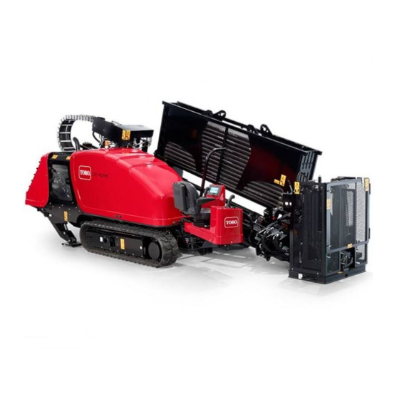
Toro 4045 Installation Instructions Manual
Cam sensor improvements kit, directional drill
Hide thumbs
Also See for 4045:
- Operator's manual (128 pages) ,
- Operator's manual (23 pages) ,
- Installation instructions (4 pages)
Advertisement
Quick Links
Cam Sensor Improvements Kit
4045 Directional Drill
Model No. 132-4165
This product contains a chemical or chemicals known to the State of California to
Safety
Safety and Instructional Decals
Loose Parts
Use the chart below to verify that all parts have been shipped.
Procedure
1
2
© 2015—The Toro® Company
8111 Lyndale Avenue South
Bloomington, MN 55420
Proposition 65 Warning
cause cancer, birth defects, or reproductive harm.
125-6184
Description
Thrust washer
Washer
Flange locknut
Rod-loader sensor
Bracket
Plate
Flange nut
Bolt (M6–1 x 16 mm)
Hex nut (M10)
Flat washer
Bolt (M10–1 x 40 mm)
Bolt (M4 x 10 mm)
Nut (M4)
Sensor harness adapter
Register at www.Toro.com.
WARNING
CALIFORNIA
Qty.
1
1
1
1
1
1
2
2
1
2
1
2
2
1
Form No. 3395-934 Rev A
Installation Instructions
Use
Install the rod-loader spacer.
Install the rod-loader sensor.
Original Instructions (EN)
All Rights Reserved *3395-934* A
Printed in the USA
Advertisement

Summary of Contents for Toro 4045
- Page 1 Form No. 3395-934 Rev A Cam Sensor Improvements Kit 4045 Directional Drill Model No. 132-4165 Installation Instructions WARNING CALIFORNIA Proposition 65 Warning This product contains a chemical or chemicals known to the State of California to cause cancer, birth defects, or reproductive harm.
- Page 2 Procedure Description Qty. Bracket Bolt (M12-1 3/4 x 60 mm) Locknut (M12) Hex nut (M10) Bolt (M4) Install the rod cam sensor. Sensor assembly Nut (M4) Cotter pins Sensor harness adapter Sensor-connector clip Removing the rotary pump supply and Gasket drain orifices.
- Page 3 Important: Move the rod loader assembly as far as possible so that there is not a gap between the rod-loader pivot and the loader assembly (Figure Installing the Rod Loader 5. Slide the pivot pin out to allow the installation for the washer (Figure Sensor...
- Page 4 Figure 8 1. Notch 11. Ensure that the gap between the magnetic sensor bolt and the sensor is 0.12 to 0.24 inch. Figure 7 12. Secure the sensor to the bracket with a cable tie as 1. Flange nut 7. Apply thread-locking compound when shown in Figure...
- Page 5 Installing the Rod Cam Sensor Parts needed for this procedure: Bracket Bolt (M12-1 3/4 x 60 mm) Locknut (M12) Hex nut (M10) Bolt (M4) Sensor assembly Figure 11 Nut (M4) Cotter pins 2. Place the elevator cylinder aside to gain access to the Sensor harness adapter sensor bracket.
- Page 6 5. Install the bolt (M10-1 x 40 mm), 2 flat washers, and the hex nut (M10) onto the bracket plate and pivot pin as shown Box C of Figure Note: Use the washers to center the bracket and plate. 6. Tighten the hardware as shown in Box D of Figure 7.
- Page 7 Removing the Rotary Pump Supply and Drain Orifices Parts needed for this procedure: Gasket Procedure Important: Allow the engine to cool. 1. Place a drain pan under they rotary pump Figure 16 2. Cap off the case drain line from the rotary pump to 1.
- Page 8 Checking the Neutral Adjustment 1. Install a 1000 psi gauge in each of the displacement control ports (M4 and M5). Figure 19 1. T40, T30, and T20 orifices 8. Remove the spring (T30) and supply orifice (T20) from the control (Figure 19).
- Page 9 Installing the Cap and Decal Parts needed for this procedure: Monitor cap Decal Figure 22 Procedure 1. Decal Gently lift the monitor away from the console using a flat-head screwdriver in the gaps as shown in Box A of Figure Figure 21 1.
- Page 10 Notes:...
- Page 11 Notes:...


Need help?
Do you have a question about the 4045 and is the answer not in the manual?
Questions and answers