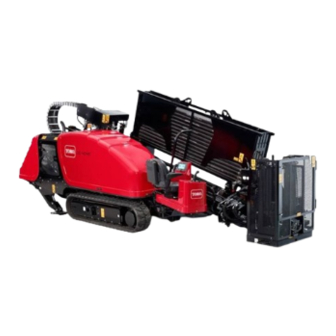
Toro 4045 Installation Instructions
Stake down guards directional drill
Hide thumbs
Also See for 4045:
- Operator's manual (128 pages) ,
- Operator's manual (23 pages) ,
- Installation instructions manual (12 pages)
Advertisement
Stake Down Guards
4045 Directional Drill
Model No. 23807
Model No. 23807E
This product contains a chemical or chemicals known to the State of California to
Safety
Safety and Instructional Decals
1. Warning—hazard area; keep at least 3 meters (10 feet)
away from the machine while in operation.
© 2015—The Toro® Company
8111 Lyndale Avenue South
Bloomington, MN 55420
Proposition 65 Warning
cause cancer, birth defects, or reproductive harm.
125-6179
Register at www.Toro.com.
WARNING
CALIFORNIA
Form No. 3396-148 Rev B
Installation Instructions
Original Instructions (EN)
All Rights Reserved *3396-148* B
Printed in the USA
Advertisement
Table of Contents

Summary of Contents for Toro 4045
- Page 1 Form No. 3396-148 Rev B Stake Down Guards 4045 Directional Drill Model No. 23807 Model No. 23807E Installation Instructions WARNING CALIFORNIA Proposition 65 Warning This product contains a chemical or chemicals known to the State of California to cause cancer, birth defects, or reproductive harm.
- Page 2 8. Loosely install the assembly to the frame using 5 bolts (M8-1 1/4 x 35 mm) as shown in Figure Preparing the Machine and Installing the Left Guard Parts needed for this procedure: Proximity-sensor cap Guard cover Guard-support bracket U-nut Bolt (M8-1 1/4 x 35 mm) Left guard Figure 2...
- Page 3 11. Install the guard assembly onto the frame (Figure using 6 bolts (M8-1 1/4 x 35 mm). 12. Torque the bolts to 23 to 29 N-m (17 to 21 ft-lb). 13. Install the left guard assembly using 1 bolt (M8-1 1/4 x Installing the Right Guard 30 mm), 1 locknut (M8), 1 Bolt (M12-1 3/4 x 120 mm), Brackets...
- Page 4 Installing the Stakedown Guard Parts needed for this procedure: Stakedown guard Bolt (M8-1 1/4 x 30 mm) Locknut (M8) Figure 6 Procedure 1. Bolt (M12-1 3/4 x 120 mm) 4. Upper bracket, large 2. Bolt (M8-1 1/4 x 30 mm) 5.


Need help?
Do you have a question about the 4045 and is the answer not in the manual?
Questions and answers