Table of Contents
Advertisement
Advertisement
Table of Contents

Related Manuals for Toro 2024


Summary of Contents for Toro 2024
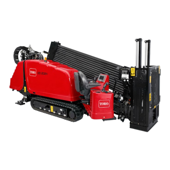
- Page 1 Form No. 3402-253 Rev A 2024 Directional Drill Model No. 23800A—Serial No. 315000001 and Up Model No. 23800C—Serial No. 315000001 and Up Model No. 23800TE—Serial No. 315000001 and Up Model No. 23800W—Serial No. 315000001 and Up *3402-253* A Register at www.Toro.com.
- Page 2 Conformity (DOC) sheet. product damage. You are responsible for operating the product properly and safely. WARNING You may contact Toro directly at www.Toro.com for product safety and operation training materials, accessory information, CALIFORNIA help finding a dealer, or to register your product.
-
Page 3: Table Of Contents
Contents Electrical System Maintenance ........72 Servicing the Battery..........72 Charging the Battery ..........73 Safety ................4 Jump-Starting the Machine ........73 Training ..............4 Drive System Maintenance .........74 Preparation............. 4 Checking the Oil Level for the Planetary General Operation ..........4 Drive ..............74 Driving Safety ............ -
Page 4: Safety
Operator’s before use. Manual . Modifications to this machine should only be made by either the manufacturer or an Authorized Toro • Use extra care when handling fuels. They are flammable Dealer. -
Page 5: Driving Safety
Driving Safety • Use care when loading or unloading the machine onto a trailer. You drive the machine to and from the work site with the use • Watch for traffic when crossing roadways. of a tethered remote. When driving the machine, observe the following safety precautions: •... -
Page 6: Drilling Safety
Drilling Safety Drilling Danger Zone The danger zone is the area within and around the machine • Always lower the safety bar before drilling (Figure where a person is exposed to the risk of injury. This proximity • Ensure that no one approaches a pipe while it is spinning. includes where a person can be reached by operational The pipe can snag on clothing and cause amputation movement of the machine, its working devices, auxiliary... - Page 7 Gas Line Safety Utility Line Color Refer to the following table for the proper utility line and the WARNING corresponding utility line color (USA and Canada). If you damage a gas line, an immediate explosion Utility Line Utility Line Color and fire hazard could occur.
-
Page 8: Maintenance And Storage
Clean debris from attachments, drives, mufflers, and filling. engine to help prevent fires. Clean up oil or fuel spillage. • Use only genuine Toro replacement parts to ensure that • Let the engine cool before storing and do not store near original standards are maintained. -
Page 9: Safety And Instructional Decals
Safety and Instructional Decals Safety decals and instructions are easily visible to the operator and are located near any area of potential danger. Replace any decal that is damaged or lost. Battery Symbols Some or all of these symbols are on your battery 125-1621 1. - Page 10 125-1641 1. Forward left 6. Forward right 2. Increase rpm 7. High 3. Engine speed 8. Track speed 4. Decrease rpm 9. Low 5. Reverse left 10. Reverse right 125-6107 1. Crushing hazard of hand and foot—keep hands and feet away.
- Page 11 125-6109 1. Electrical shock hazard—when the Zap-Alert system is activated by a power strike, do not leave the operator’s position or touch the ground and the machine at the same time; the machine will be energized with electrical power. 125-6114 1.
- Page 12 125-6116 1. Falling hazard—do not move the machine when someone is in the operator’s position. 125-6118 1. Crushing hazard, machine movement—read the Operator’s Manual. 125-6119 1. Entanglement hazard—keep away from moving objects. 125-6117 1. Falling hazard—do not stand on the machine while it is moving.
- Page 13 125-6123 1. Load pipes from back row first. 125-6121 1. Engine—heating light 5. Fluid pump on 2. Engine—stop 6. Fluid pump off 3. Engine—run 7. Drill-pendant receptacle 4. Engine—start 8. Drive-pendant receptacle 125-6124 1. Center the pipe joint between the upper and lower wrenches.
- Page 14 125-6125 125-6126 1. Warning—read the 6. Press and hold to move Operator’s Manual. the drill carriage at high 1. Entanglement hazard—keep away from moving parts. speed up or down the drill frame. 2. Explosion hazard; 7. Mode I—spin drill spindle electrical shock clockwise.
- Page 15 125-6129 1. Hot surface—keep away from hot surfaces. 125-6140 1. Rotate the chair. 125-6152 1. Move seat forwards and backwards. 125-6131 1. Warning—stay at least 3 m (10 ft) away from the machine. 125-6694 1. Tie-down point 125-6137...
- Page 16 125–8483 125-8473 1. Hydraulic fluid; read the Operator’s Manual. 1. Explosion hazard—wear 3. Fire hazard—keep open eye protection. flames away. 4. Poison hazard—do not 2. Caustic liquid/chemical burn hazard—rinse tamper with the battery. affected area and seek medical assistance. 125-6113 1.
- Page 17 125-6112 1. Exit-side lockout—reset light 14. Work lights—Off 2. Exit-side lockout—drill-enabled light 15. Press and hold to increase engine speed. 3. Receiver-battery-status light 16. Engine speed 4. Engine—start 17. Press and hold to decrease engine speed. 5. Press down to stop the engine; pull up to start the engine. 18.
-
Page 18: Product Overview
Product Overview Figure 5 1. Drill carriage 6. Front hood 2. Zap-alert strobe 7. Right stabilizer 3. Operator seat 8. Rear hood 4. Control panel 9. Thrust frame 5. Track... - Page 19 Figure 6 1. Stake-down cage 5. Rear-control panel 2. Pipe holder 6. Left stabilizer 3. Safety bar 7. Stake-down plate 4. Drilling-fluid-pump inlet...
- Page 20 Figure 7 1. Thrust frame 4. Upper wrench 2. Drill carriage 5. Lower wrench 3. Drill spindle 6. Pipe wiper...
-
Page 21: Controls
Controls Operator-Controls Covers The covers protect the operator controls from adverse Refer to the following sections for the appropriate machine weather conditions, such as rain, wind, sunlight, etc. Remove controls: them before using the machine and replace them before • Operator Platform leaving the machine for the day. -
Page 22: Control Panel
To release the platform and swing it out or in, press up on the Exit-Side Lockout—Drill-enabled Light front platform latch (Figure 11). This light (Figure 12) illuminates green when the exit-side-lockout feature has been turned off and reset and the machine is ready to drill. Exit-Side Lockout—Reset Switch Press this switch (Figure... -
Page 23: Left Joystick-Mode I
Only operate in this mode if absolutely necessary; you could damage the pipe cam or pipes if you do not align them correctly. If the sensor fails, contact your Authorized Toro Dealer for repair. g021833 Figure 13 Joystick—Forward... -
Page 24: Left Joystick-Mode Ii
Only operate in this mode if absolutely necessary; you could damage the pipe cam or pipes if you do not align them correctly. If the sensor fails, contact your Authorized Toro Dealer for repair. g021833 Figure 14 Joystick—Forward... -
Page 25: Right Joystick-Mode I
Right Joystick—Mode I Lower Button Note: The joystick controls vary depending on the control Press this button to turn the drilling-fluid pump on or off. mode you select when powering up the machine. There are 2 control modes: Mode I and Mode II; refer to the Trigger Control-Select Screen in the Software Guide for information Press and hold the trigger to move the drill carriage at high... -
Page 26: Right Joystick-Mode Ii
Right Joystick—Mode II Lower Button Note: The joystick controls vary depending on the control Press this button to turn the drilling-fluid pump on or off. mode you select when powering up the machine. There are 2 control modes: Mode I and Mode II; refer to Control-Select Trigger Screen in the Software Guide for information on setting the Press and hold the trigger to move the drill carriage at high... -
Page 27: Rear Control Panel
Exit-Side-Lockout System (Standard Engine, Key Switch Range) The key switch has 3 positions as follows (Figure 18): The exit-side-lockout system provides the individuals working around the machine with a means to disable the drill pipe from rotating and thrusting. For more information and instructions, refer to the Operator’s Manual for the Exit-side-lockout system. -
Page 28: Drill Frame And Stabilizer Controls
Drill Frame and Stabilizer Controls Drive Pendant Refer to Figure 17 for location. g021843 Figure 19 1. Drill-frame tilt lever 3. Right-stabilizer lever 2. Left-stabilizer lever g021855 Figure 20 Stabilizer Levers 1. Engine-speed switch 4. Drive-speed switch Use the stabilizer levers to raise and lower the stabilizers. 2. -
Page 29: Drill Pendant
Drive-Speed Switch Left Switch • When connected to the drill-pendant receptacle, move The switch sets the speed at which the machine will travel. this switch up to move the drill carriage forward or down Move the switch up for high speed or down for low speed. to move the drill carriage rearward. -
Page 30: Specifications
(Figure 23). its capabilities. Contact your Authorized Service Dealer or Distributor or go to www.Toro.com for a list of all approved attachments and accessories. Important: Use only Toro approved attachments. Other attachments may create an unsafe operating environment or damage the traction unit. -
Page 31: Operation
Operation Refer to Preparing the Job Site and the Machine (page for instructions on preparing the job site and the machine. Note: Determine the left and right sides of the machine 4. Drill the bore. from the normal operating position. You drill the bore in three stages: Understanding Horizontal A. -
Page 32: Gathering Site Information
Gathering Site Information DANGER Contacting underground hazards with the Planning the Initial Route machine while drilling or reaming can cause explosion, electrocution, breathing problems, Before you can begin boring, you need to plan the route you severe trauma, and death to you or bystanders. will bore and prepare as follows: –... - Page 33 – Electrical power lines – Crystalline silica and other dust If you will be drilling through or cutting concrete, DANGER sand, or other substances that create dusts or fumes, you need to ensure that you and all workers wear Drilling into an electric power line will cause breathing protection to protect your lungs from the the machine to become electrified and may dust.
-
Page 34: Planning The Bore Path
Planning the Bore Path Before setting up the job site, you need to plan the bore path, including the following: g021764 Figure 24 1. Bore entry 4. Obstacle 2. Beginning-of-bore-at-depth point 5. End-of-bore-at-depth point and bore exit 3. Bore depth •... - Page 35 g021765 Figure 25 1. 20 cm (8 inches) This flexibility is often rated in materials as a minimum bend radius, which is the radius of the circle formed if the material or pipes, connected together, were bent to form a giant circle. The minimum radius of a circle made with the pipe used with this machine is 31 m (101 ft).
- Page 36 Note: The depths given in the following table are for 3 m (10 ft) of combined drill head and pipe. As you steer up, the pitch of the steered section will change and can be monitored with the receiver. Use the following table to identify how many lengths of pipe will be necessary to insert and steer to the beginning point and help you choose an entry point.
- Page 37 Toro recommends that you start the entry point a (26%) on level ground: distance back from your beginning-at-depth point by the •...
- Page 38 • The following example illustrates the process given an You insert the first 3 m (10 ft) of drill bit/pipe into the installation using the machine at an 18% pitch on level ground with no steering. The end of the drill bit will be ground: 53 cm (21 inches) deep (Figure...
-
Page 39: Preparing The Job Site And The Machine
Preparing the Job Site and the Testing the Zap-Alert System Machine The Zap-Alert system is an electric strike sensing device on the machine that triggers a strobe light and audible alarm in Before drilling, prepare the job site and machine as follows: the event that the drill bit, reamer, or stake breaks into an energized power line. - Page 40 If either the audible alarm or the strobe light failed to trigger when you pressed the button, have them TEST repaired before drilling with the machine. Mounting a Fire Extinguisher Mount your fire extinguisher below the operator seat (Figure 32). Note: A fire extinguisher is not provided with the machine.
- Page 41 Loading Drill Pipes into the Pipe Holder Before using the machine, fill the pipe holder with up to 40 drill pipes. Figure 33 1. Pipe 2. Male end 3. Clevis pins Adding Fuel 1. Remove the clevis pins from the pipe holder (Figure 33).
- Page 42 • Use of summer grade fuel above -7° C (20° F) will contribute If this is not possible, then refuel such equipment on toward longer fuel pump life and increased power compared a truck or trailer from a portable container, rather than to winter grade fuel.
- Page 43 Adjusting the Carriage Pressure Driving the Machine 1. Walk around the machine to ensure that no one is near To hydraulically adjust the carriage pressure, do the following: it. Ensure that all bystanders are clear of the area where 1. Press button 7 on the screen to turn the carriage you will be moving the machine.
- Page 44 11. After driving a few miles, pull over and check to ensure that all chains are still tight and that the machine has not moved. To unload the machine, reverse the above procedure. Figure 35 1. Upper pins 2. Lower pins 3.
- Page 45 A narrower blade Figure 39 moves through hard soils better. Contact your Authorized Toro Dealer for a complete list of available blades. 1. Sonde housing 3. Drill bit The sondes and receivers are essential to track the position 2.
- Page 46 Figure 42 1. Rear platform latch Deploying the Zap-Alert System The Zap-Alert system is an electric strike sensing device on Figure 40 the machine that triggers a strobe light and audible alarm in 1. Screw 2. Cover the event that the drill bit, reamer, or stake breaks into an energized power line.
- Page 47 3. If the ground is dry where you put the stake, soak it DANGER with water before using the machine to ensure good If the Zap-Alert system activates while drilling, the electrical contact. machine, except for the operator’s platform, will become energized.
- Page 48 Connecting to a Drilling-Fluid Source When drilling and reaming, you pump a mixture of bentonite clay, water, and sometimes other ingredients, collectively called drilling fluid or “Mud”, through the pipe and into the bore. This drilling fluid, or “Mud”, does the following for your bore: •...
-
Page 49: Drilling The Bore
Drilling the Bore Setting Up the Pump to Use a Natural Water Source To set up a pump to use a natural water source, you must Starting the First Pipe ensure that you use the Y-screen to filter all materials other than water. - Page 50 Installing the Drill Head 1. Using the exit-side-lockout transmitter, enable the exit side lockout. WARNING If the drill rotates or extends while you or others are manually working on the drill bit or pipe in front of the machine, the worker could get caught in the bit or pipe causing serious injury, amputation, or death.
- Page 51 5. Using the upper wrench, clamp the lead bar and tighten 4. Rotate the drill head counterclockwise until the spindle it to full machine torque. is completely removed from the pipe. 6. Using the exit-side-lockout transmitter, enable the 5. Spray the spindle with thread joint compound, then exit-side lockout.
-
Page 52: Backreaming And Pullback
The following reamers are available from your Authorized head and bore the horizontal shaft, adding pipes as you go. Toro Dealer in various sizes to meet your needs and soil While boring, pay close attention to the information relayed conditions: back to you by the receiver operator about the status and •... - Page 53 5. Connect the product to the reamer using an appropriate green light will illuminate below the spray valve. pulling connection; refer to your Authorized Toro 6. Close the lower wrench onto the pipe joint. Dealer to acquire the appropriate puller to meet your requirements.
-
Page 54: Finishing The Job
Finishing the Job 17. Rotate the drill spindle counterclockwise moving rearward slowly until the spindle fully separates from Complete the following after each day of use: the pipe. • Connect the hand spray gun to the pump and clean the 18. - Page 55 Adjusting the TJC-spray Volume Filling the TJC Applicator 1. Stop the machine and stop the engine. To adjust the volume of thread-joint compound that is delivered by the applicator, complete the following: 2. Open the stake-down-guard door. 1. Loosen the jam nut on the adjustment bolt located on 3.
-
Page 56: Moving A Disabled Machine
Moving a Disabled Machine Whenever the machine is stopped and the engine is not running, the hydrostatic brakes automatically engage. Do not attempt to tow the machine if it cannot move under its own power. If possible, repair the machine at the site. If this is not possible, use a crane and a spreader bar to lift the machine onto a trailer, using the lift points shown in Figure... -
Page 57: Maintenance
Maintenance Note: Determine the left and right sides of the machine from the normal operating position. Recommended Maintenance Schedule(s) Maintenance Service Maintenance Procedure Interval • Check the gearbox drive oil. After the first 100 hours • Change the gearbox-drive oil. •... -
Page 58: Premaintenance Procedures
CAUTION If you leave the key in the ignition switch, someone could accidently start the engine and seriously injure you or other bystanders. Remove the key from the ignition before you do any maintenance. WARNING Improperly servicing or repairing the machine may cause injury or death. If you do not understand the service procedures for this machine, contact your dealer or see the service manual for this machine. -
Page 59: Using The Cylinder Lock
Using the Cylinder Lock 2. Pull the hood latch out (Figure 60). WARNING The thrust frame may lower when it is in the raised position, causing serious injury or death. Install the cylinder lock before performing maintenance that requires the thrust frame to be raised. -
Page 60: Lubrication
Lubrication 7. Store the cylinder lock next to the anti-freeze tank (Figure 63). Greasing the Machine Service Interval: Before each use or daily (Grease immediately after every washing). Grease type: General-purpose grease. 1. Park the machine on a level surface, stop the engine, and remove the ignition key. - Page 61 Figure 68 Figure 65 Thrust-frame pivot pin (Under side of machine) Front-pipe elevator and cam cylinder (drill/carriage side) Figure 69 Rear-pipe elevator (operator’s side) Figure 66 Rear-pipe elevator and cam cylinder (drill/carriage side) Figure 70 Front-pipe elevator (operator’s side) Figure 67 Stabilizer cylinder and foot (drill/carriage side;...
- Page 62 Figure 71 Stakedown motors Figure 72 Carriage-roller bearings (operator’s side shown; repeat on other side) Figure 73 Gearbox float (operator’s side shown; repeat on other side) Figure 74 Track roller (operator’s side shown; repeat on other side)
-
Page 63: Engine Maintenance
Engine Maintenance Cleaning the Crankcase-Vent Tube Service Interval: Before each use or daily—Check the crankcase-vent tube and clean it if necessary. 1. Park the machine on a level surface, stop the engine, and remove the ignition key. Figure 75 2. Open the front hood; refer to Opening the Front Hood (page 58). - Page 64 Servicing the Air-Cleaner Cover it is necessary only increases the chance of dirt entering the engine when the filter is removed. Service Interval: Every 50 hours—Remove air cleaner cover • Be sure the cover is seated correctly and seals with the and clean out debris.
- Page 65 Checking the Air-Cleaner Indicator (page 64). Note: Contact your Authorized Toro Dealer to order replacement filters. 1. Park the machine on a level surface, stop the engine, and remove the ignition key.
-
Page 66: Servicing The Engine Oil And Filter
(Figure 83). Toro Premium Engine Oil is available from an Authorized Toro Service Dealer in either 15W-40 or 10W-30 viscosity with API classification CH-4 or higher. See the parts catalog for part numbers. - Page 67 8. Align the oil filter to the oil-filter adapter and rotate it clockwise until the seal of the oil filter contacts the oil-filter adapter (Figure 86). Note: Do not use an oil filter strap wrench to install the new oil filter. The wrench can dent an oil filter and therefore cause a leak.
-
Page 68: Adjusting The Valve Clearance
Service Interval: After the first 250 hours Every 2,000 hours Refer to the engine owner’s manual, included with the machine, for the adjustment procedure. If you cannot adjust the valve clearance, contact your Authorized Toro Service Dealer for valve adjustment. -
Page 69: Fuel System Maintenance
Fuel System and drain any water and sediment from the fuel filter (Figure 89). Maintenance Note: If the fuel-water separator has any water or sediment, also drain the water and sediment from DANGER the fuel tank; refer to Draining Water from the Fuel Tank (page 69). -
Page 70: Priming The Fuel System
8. If the engine does not start after priming the fuel system and making several attempts to start the engine, bleed the high-pressure fuel lines; refer to your engine owner’s manual or contact your Authorized Toro Service Dealer for assistance. WARNING The fuel system is under high pressure. -
Page 71: Checking Fuel Lines And Connections
4. Start the engine and check for leaks at the fuel filters. Checking Fuel Lines and Connections Service Interval: Every 500 hours/Yearly (whichever comes first)—Inspect the fuel lines and connections. Inspect the fuel lines and connections for deterioration, damage, or loose connections. Draining and Cleaning the Fuel Tank Service Interval: Every 1,000 hours/Yearly (whichever... -
Page 72: Electrical System Maintenance
Rinse with clear water. Coat To prevent the battery electrolyte from freezing, the battery posts and cable connectors with Grafo 112X keep the battery fully charged. (skin-over) grease (Toro Part No. 505-47) or petroleum jelly to prevent corrosion. WARNING WARNING •... -
Page 73: Charging The Battery
Charging the Battery Battery-Charger Table Charger setting Charging time WARNING 4 to 6 amperes 30 minutes Charging the battery produces gasses that can 25 to 30 amperes 10 to 15 minutes explode. 8. When the battery is fully charged, unplug the charger Do not smoke near the battery and keep sparks and from the electrical source, then disconnect the charger flames away from battery. -
Page 74: Drive System Maintenance
Figure 94 Planetary drive oil capacity: approximately 1.4 L (1.5 US qt) 1. Jumper-cable clamp 4. Ground point (unpainted Toro Premium Gear Oil is available from an Authorized Toro (positive) bolt) Service Dealer. See the parts catalog for part numbers. -
Page 75: Changing The Oil For The Planetary Drive
Changing the Oil for the Planetary Drive Service Interval: After the first 250 hours—Change the planetary oil. Every 800 hours—Change the planetary oil (or yearly, whichever comes first). Note: Change the oil when it is warm, if possible. 1. Park the machine on a level surface. 2. -
Page 76: Servicing The Tracks
9. Place the guard back into place and install the 2 bolts (Box A of Figure 97). 10. Install the 2 other bolts securing the lid onto the gearbox (Box A of Figure 97). 11. Torque the bolts to 23 to 29 N∙m (17 to 21 ft-lb). Servicing the Tracks Service Interval: Before each use or daily—Check the track tension. -
Page 77: Cooling System Maintenance
Cooling System 5. Remove excess grease from around the valve. 6. Install the cover and retaining bolts. Maintenance 7. Repeat steps through to tighten the track tension on the other side. Coolant specification: 50/50 solution of ethylene-glycol antifreeze and water or equivalent Loosening the Track Tension Engine and Radiator coolant capacity: 16.77 L (17.7 US If the track seems tight, loosen the track tension as follows:... -
Page 78: Checking The Coolant Level In The Reservoir
Checking the Coolant Level in 1. Park the machine on a level surface, stop the engine, and remove the ignition key. the Reservoir 2. Allow the engine to cool. Service Interval: Before each use or daily 3. Open the front hood and rear hood. Important: Do not remove the radiator filler cap during 4. -
Page 79: Checking The Condition Of Cooling-System Components
Checking the Condition of Cooling-System Components Service Interval: Every 300 hours/Yearly (whichever comes first) Check the condition of the cooling system for leaks, damage, dirt, and loose hoses and clamps. Clean, repair, tighten, and replace the components as necessary. Checking the Concentration of the Coolant Figure 102 Service Interval: Every 1,000 hours/Yearly (whichever... - Page 80 D. Operate the engine for 5 minutes or until the coolant temperature indicates 82°C (180°F), and then stop the engine. CAUTION The water is hot and can cause burns. Stay away from the discharge end of the coolant drain plug. Figure 103 E.
-
Page 81: Belt Maintenance
Belt Maintenance Servicing the Engine-Drive Belt WARNING Contacting a rotating belt can cause serious injury or death. Stop the engine and remove the ignition key before working near belts. G022028 Figure 105 Checking the Condition of the Belt 1. Coolant level (at the 3. - Page 82 Checking the Tension of the Belt Adjusting the Tension of the Belt 1. Park the machine on a level surface, stop the engine, Service Interval: Every 1,000 hours and remove the ignition key. 1. Park the machine on a level surface, stop the engine, 2.
-
Page 83: Hydraulic System Maintenance
• Safely relieve all pressure in the hydraulic system Toro Dealer for part numbers.) before performing any work on the hydraulic Alternate fluids: If the Toro fluid is not available, other system. fluids may be used provided they meet all the following material properties and industry specifications. - Page 84 Changing the Hydraulic-Fluid Return Filter Service Interval: Every 500 hours/Every 6 months (whichever comes first) 1. Park the machine on a level surface, stop the engine, and remove the ignition key. 2. Open the front hood. 3. Clean the area around the filler neck and cap of the hydraulic tank.
- Page 85 Important: If the fluid becomes contaminated, contact of the hydraulic controls to distribute hydraulic fluid your Authorized Toro Dealer, because the system must throughout the system. Also check for leaks; then stop be flushed. Contaminated fluid looks milky or black the engine.
-
Page 86: Drilling-Fluid Pump Maintenance
Oil: SAE 30-weight, non-detergent oil above 0° C (32° F) • Keep your body and hands away from pin Toro Premium Engine Oil is available from your dealer. See hole leaks or nozzles that eject high pressure the parts catalog for part numbers. Also, refer to the Engine hydraulic fluid. -
Page 87: Preparing The Drilling-Fluid System For Cold Weather
Preparing the Drilling-Fluid 4. Ensure that the oil is at the oil-fill line as shown in Figure 111. System for Cold Weather Note: If the oil is below the oil-fill line, refer to step Prepare the machine as follows after drilling if the temperature Changing the Drilling-Fluid Pump Oil (page 87) will be below 0°... -
Page 88: Cleaning
Cleaning Cleaning with the Spray-Hose Attachment Service Interval: Before each use or daily The machine comes with a spray-hose attachment that you can use to clean the machine and pipes. Important: Do not spray any electronic component of G022141 the machine and ensure that the hood is down before cleaning the machine with the spray-hose attachment. -
Page 89: Cleaning Plastic And Resin Parts
7. Turn the drilling-fluid pump to the O position through the display screen; refer to the Main Drill Functions Displayed in the Pressure Screen in the Software Guide. 8. Using the spray-hose attachment, hold down the lever and spray down the machine and pipes. Cleaning Plastic and Resin Parts Figure 118... -
Page 90: Storage
Storage 1. Stop the engine and remove the key. 2. Remove dirt and grime from the entire machine. Important: You can wash the machine with mild detergent and water. Avoid excessive use of water, especially near the control panel, engine, hydraulic pumps, and motors. -
Page 91: Troubleshooting
Troubleshooting Problem Possible Cause Corrective Action The starter will not crank. 1. The B switch is in 1. Turn the B switch ATTERY ISCONNECT ATTERY ISCONNECT the O position. to the O position. 2. The electrical connections are 2. Check the electrical connections for corroded or loose. - Page 92 Problem Possible Cause Corrective Action The engine starts, but will not keep 1. The fuel tank vent is restricted. 1. Loosen the cap. If the engine runs with running. the cap loosened, replace the cap. 2. Dirt or water is in the fuel system. 2.
- Page 93 Problem Possible Cause Corrective Action The engine overheats. 1. More coolant is needed. 1. Check and add coolant. 2. There is restricted air flow to the 2. Inspect and clean the side panel radiator. screens with every use. 3. The crankcase oil level is incorrect. 3.
-
Page 94: Index
Index Steering ....... . . 51 Flushing ....... . . 79 Boring the entry shaft . - Page 95 Connecting to a fluid source..48 Horizontal shaft Connecting to a natural water Boring........52 Fiber-optic lines source.
- Page 96 Reset Planetery drive Preparing the job site and machine ..39 Exit-side lockout..... . 22 Changing .
- Page 97 Hard hat ........4 Water lines Hearing protection ......4 Safety precautions.
- Page 98 Notes:...
- Page 99 The Way Toro Uses Information Toro may use your personal information to process warranty claims, to contact you in the event of a product recall and for any other purpose which we tell you about. Toro may share your information with Toro's affiliates, dealers or other business partners in connection with any of these activities. We will not sell your personal information to any other company.
- Page 100 If for any reason you are dissatisfied with your Underground Dealer’s service or have difficulty obtaining guarantee information, contact the Toro importer. Australian Consumer Law: Australian customers will find details relating to the Australian Consumer Law either inside the box or at your local Toro Dealer.
Need help?
Do you have a question about the 2024 and is the answer not in the manual?
Questions and answers