
Related Manuals for DediProg NuProg-E


Summary of Contents for DediProg NuProg-E
- Page 1 DediProg User Manual 09/2019 NuProg-E Engineering UFS/eMMC Programmer User Manual Version 2.0 © DediProg Technology Co., Ltd. 2019 All rights reserved.
-
Page 2: Table Of Contents
NuProg-E User Manual Table of Contents INTRODUCTION ..........................4 PRODUCT INFORMATION......................... 4 III. SYSTEM REQUIREMENT ........................5 PRODUCT DESCRIPTIONS ......................... 6 4.1 E ..............................6 XTERIOR 4.2 I ........................... 7 NSTALL OCKET DAPTOR DEDIWARE QUICK INSTALLATION ....................8 5.1 S .......................... - Page 3 This document is provided as a guideline and must not be disclosed without consent of DediProg. However, no responsibility is assumed for errors that might appear. DediProg reserves the right to make any changes to the product and/or the specification at any time without notice.
-
Page 4: Introduction
As for eMMC, it supports User Area, Boot 1/2 and RPMB basic read and write; also supports ExtCSD, GPP1~4 partition, read and write, as well as enhanced mode setting. With the high speed USB 3.0, the NuProg-E is the finest programmer for UFS and eMMC development. For more information, please visit our website. -
Page 5: System Requirement
NuProg-E User Manual III. System Requirement CPU: Intel i5 or Above Windows 7/8/8.1/10 USB Port: USB 2.0 and USB 3.0 Free Dish Space: At least twice of the programming memory CD ROM: It is necessary for installing the software *Since UFS and eMMC have mass volumes, please reserve enough space for buffering. -
Page 6: Product Descriptions
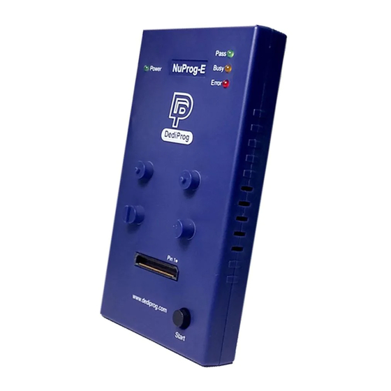
NuProg-E User Manual IV. Product Descriptions 4.1 Exterior A. Power Signal Light B. Operation Lights C. Programming Socket Sites D. Start Button Fig. 4-1 E. Power Connector Fig. 4-2 F. USB 3.0 Port www.dediprog.com... -
Page 7: Install Socket Adaptor
NuProg-E User Manual A. Power Signal Light The light indicates the programmer is powered on. B. Operation Lights Red LED (Error): Error; programming has failed. Yellow LED (Busy): The programmer is operating. Green LED (Pass): Passed; the programming has completed successfully. -
Page 8: Dediware Quick Installation
NuProg-E User Manual V. Dediware Quick Installation The software is provided with the purchase of NuProg-E programmer. The newest version will also be available on our website. www.dediprog.com 5.1 Software Installation 5.1.1 Install DediWare Fig. 5-1 www.dediprog.com... - Page 9 NuProg-E User Manual 5.1.2 When you install NuProg-E software for the first time, please install the USB Driver. Otherwise, the computer will not be able to recognize the programmer. Fig. 5-2 Fig. 5-3 www.dediprog.com...
- Page 10 NuProg-E User Manual 5.1.3 After installation, Dediware and NuProg icons will appear on the desktop. The Dediware icon is for StarProg and ProgMaster series programmer while the NuProg icon is for NuProg-E programming. StarProg/ProgMaster NuProg-E Fig. 5-4 There is another icon called DediWare_CLI; it is the Command Line software for StarProg Series programmers, so it does not support NuProg series.
-
Page 11: Install Nuprog-E Programmer
5.2 Install NuProg-E Programmer 5.2.1 Place an IC into the socket adaptor and attach it to the socket site. 5.2.2 Connect NuProg-E to the computer (USB 3.0 is recommended). 5.2.3 Once you open Dediware, it will detect a programmer automatically and will be available for programming. -
Page 12: Main Menu And Functions
NuProg-E User Manual 5.3.2 Software Introduction (UFS Part) Log Window Main Menu and Functions Programmer Information Batch Config CheckSum Setting Information data Fig. 5-7 A. Main Menu and Functions Fig. 5-8 www.dediprog.com... - Page 13 NuProg-E User Manual A-1. Main Menu- Advance Fig. 5-9 Language: English, Simplified Chinese, and Traditional Chinese. Log in: Set up the IP address for remote controls. General options: Set up a temporary file for saving buffers. Since large volume IC has a great demand of storage.
- Page 14 LCD Firmware Update: Update the LCD firmware version of the NuProg-F8. Download default vector table: Update the master vector files. Reset Programmer Order: Reset all NuProg programmers’ order. Launch Calculator: It opens the calculator. User Manual: It links to DediProg’s user manuals. www.dediprog.com...
- Page 15 NuProg-E User Manual A-3. Functions (From Top to Bottom; Left to Right) Fig. 5-12 Detect: Choose correct IC type to detect IC (Fig. 5-13) or choose the model number manually. If the data list has the corresponding model number that is supported, software will automatically import the values of the UFS, and the Log will appear as below (Fig.
- Page 16 NuProg-E User Manual Fig. 5-15 Load: Import the programming file and set the values according to your requirements. Fig. 5-16 www.dediprog.com...
- Page 17 NuProg-E User Manual Value Descriptions: File Format: The format of the programming file. File Checksum: The file checksum’s calculation method. File Offset: Appoint an address to start loading the buffer. File Path: Assign a path for the programming file.
- Page 18 NuProg-E User Manual Buffer: Temporary files. Select a partition to display the LUN and the related Option values of the UFS. Fig. 5-17 Buffer Checksum: It will calculate the assigned Partition checksum. Goto: Assign a Buffer address ...
- Page 19 NuProg-E User Manual Fig. 5-18 www.dediprog.com...
- Page 20 NuProg-E User Manual Descriptors: It provides all UFS descriptor settings. Use Write Descriptor to write; test read is also available on this page (Fig 5-19). Able to assign different descriptors Able to Save, Load, and Read the configuration descriptors Fig.
- Page 21 NuProg-E User Manual Attributes: Provides set up and read for each LUN attribute values. Use Write Attribute to write; test read is also available on this page. Able to select different LUN Able to Save/Load/Refresh/Export Fig. 5-20 Assign a LUN NO according to your need and Refresh to read the attributes, please ensure the information is written correctly, and then save the settings for next time usage.
- Page 22 NuProg-E User Manual Flags: Set up the settings and write through the Write Flag; test read is also available on this page. Export/Save/Load/Refresh Fig. 5-21 Change the settings according to your needs, and then write through the Write Flag.
- Page 23 NuProg-E User Manual IC Info: Chip information and cautions (Not supported yet). Save Prj: After loading the programming files, users can use this feature to save the files/chip info into a local file folder. ReadIC: Read and display the IC data.
- Page 24 NuProg-E User Manual Functions Buffer Checksum: Show the buffer checksum of the partition for verification. Goto: Enter the number line in order to go to the address for examination. Save Memory: Save the actual IC data of the selected partition or select a range to save.
- Page 25 NuProg-E User Manual Program: Program the data to the IC. Select all, one of the LUN, or Descriptors/Attributes/Flags Program. Fig. 5-25 Verify: Verify and compare the programming file with the IC data. Select all, one of the LUN, or Descriptors/Attributes/Flags Program.
-
Page 26: Log Window
NuProg-E User Manual B. LOG Window: Display and record the entire process and the results. Fig. 5-28 C. Programmer Information: Display the programmer name, the firmware version, and the FPGA version. Fig. 5-29 D. IC Information: Display all the data of the selected IC. -
Page 27: Checksum Data
NuProg-E User Manual E. CheckSum Data: Display programming file name, file size, corresponding partition, and file checksum. Fig. 5-31 F. Batch Config Setting: It displays the batch settings that are selected in the Config window. When you use AutoBatch, the system will follow the listed order when programming. - Page 28 NuProg-E User Manual 5.3.3 Examples Example 1 Only update LUN0, LUN1, and LUN2 for the IC that has been initialized, please follow the steps below: Step 1. Install an IC on the programmer and open the software. The software will automatically detect the IC model and the LUN status.
- Page 29 NuProg-E User Manual Step 2. Load a programming file: load a programming file to each LUN partition separately (Fig. 5-35). Since LUN0 file is bigger and more dispersed, please select the Skip Blank Value to reduce the programming time. Fig. 5-35 After importing a file, the corresponding programming file and the File CheckSum will be shown in the Check Sum Area.
- Page 30 NuProg-E User Manual Step 3. For single programming function In order to re-work IC, please write in the order of wipe (*Note) > Program > Verify LUN0~2. If IC has not been programmed yet, then skip wipe and start from Program >...
- Page 31 NuProg-E User Manual Step 4. Batch Programming Step4-1. Set up Batch Setting in the Config window. Since you will only need to update the contents of LUN0~2, and the file is bigger than the original IC file, so it is not necessary to set up and program Flag, Attribute, and Descriptor again.
- Page 32 NuProg-E User Manual Example 2 If the IC is not initialized, please follow the steps below: Step 1. If the LUN number still remains at zero (Fig. 5-40) even after the IC and socket are installed, then it might indicates the LUN is unable to write, please partition the LUN first.
- Page 33 NuProg-E User Manual Fig. 5-42 After changing the settings, click Write Descriptor to start the programming process, and then Detect again; the Chip Information will display the updated status of the LUN. Fig. 5-43 Next, follow the steps in Example 3.
- Page 34 NuProg-E User Manual Example 3 If there are only two partitions originally and you want to add a third section, please follow the steps below: Step 1. Open the software and set up the configuration descriptor in the Config window.
- Page 35 NuProg-E User Manual Example 4 Duplicate the bootable master IC to other blank IC through Auto Batch programming. Step 1. First, insert a master IC. Once the IC has been detected, save the contents of Descriptor/Attributes/Flags/LUN of the master IC.
-
Page 36: Precautions When Using Nuprog-E (For Ufs) Software
Step 2. Load the Image file. Step 3. Insert a blank IC, and then click Auto batch to start programming process. 5.4 Precautions when using NuProg-E (For UFS) software Click Config will read the descriptor, attributes, and flags of the IC. -
Page 37: Nuprog Installation Guide (Emmc Part)
NuProg-E User Manual 5.5 NuProg Installation Guide (eMMC part) 5.5.1 Double Click the NuProg icon Fig. 5-49 5.5.2 Software Introduction (eMMC part) Log Window Main Menu and Programmer Functions Information Batch Config CheckSum Information Setting data Fig. 5-50 www.dediprog.com... -
Page 38: Main Menu And Functions
NuProg-E User Manual Main Menu and Functions Fig. 5-51 A-1. Main Menu- Advance Fig. 5-52 Language: Provide English, Simplified Chinese, and Traditional Chinese Log in: Set up the IP address for remote controls. General options: Set up a temporary file for saving buffers. Since large volume IC has a great demand of storage. - Page 39 LCD Firmware Update: Update the LCD firmware version of the NuProg-F8. Download default vector table: Update the master vector files. Reset Programmer Order: Reset all NuProg programmers’ order. Launch Calculator: It opens the calculator. User Manual: It links to DediProg’s user manuals. www.dediprog.com...
- Page 40 NuProg-E User Manual A-3. Functions (From Top to Bottom; Left to Right) Fig. 5-55 Detect: Choose the correct IC type to detect the IC (Fig. 5-56) or choose the model number manually. If the data list has the corresponding model number that is supported, software will automatically import the values of the eMMC and the Log will appear as below (Fig.
- Page 41 NuProg-E User Manual Fig. 5-58 Load: Import the programming file and set the values according to your needs. Fig. 5-59 www.dediprog.com...
- Page 42 NuProg-E User Manual Value Descriptions: File Format: The format of the programming file. File Checksum: The file checksum’s calculation method. File Offset: Appoint an address to start loading the buffer. File Path: Assign the path for the programming file.
- Page 43 NuProg-E User Manual Buffer: Temporary files. Choose a partition to fully display its content. Fig. 5-60 Buffer Checksum: It will calculate the assigned Partition checksum. Goto: Assign a Buffer address www.dediprog.com...
- Page 44 NuProg-E User Manual Config: Programming Settings. It will read the contents of Descriptors/Attribute/Flags from the UFS and display on each window. Batch Setting: Double click the programming options that are listed in the Batch Operation box or click >> or << to move the options to the Operation Selected box.
- Page 45 NuProg-E User Manual Ext CSD Setting: Provide Extend CSD setting for eMMC. Set up ExtCSD on this page, and then add this option in the Batch Setting. Ext CSD value setting Fig. 5-62 Add: Add a new ExtCSD value to the list.
- Page 46 NuProg-E User Manual RPMB: Since RPMB needs a set of Key to read and write normally, so set up the RPMB key on this page. Save and load the RPMB Key Fig. 5-63 www.dediprog.com...
- Page 47 NuProg-E User Manual IC Info: Chip information and cautions. (Not supported yet) ReadIC: Read and display the IC data. Chip Area Partition selections File Area Functions Fig. 5-64 Partitions It will configure according the actual partition of eMMC, and then you switch to see different partitions.
- Page 48 NuProg-E User Manual Save Memory: Save the actual IC data of the selected partition or select a range to save. However, it is not available to save all the partitions at once. Next Different: Search and compare the next different file.
-
Page 49: Log Window
NuProg-E User Manual Verify: Verify and compare the project file with the IC. Select all or choose one of the partitions. Fig. 5-68 Auto Batch: It will program according to the listed order in the Batch Setting, which is in the Config window. -
Page 50: Ic Information
NuProg-E User Manual Fig. 5-70 D. IC Information: Display the part number and the relate information according to the selected chip. Fig. 5-71 E. CheckSum Data: Display project file name, file size, corresponding partition and file CheckSum. Fig. 5-72 F. Batch Setting: The Batch setting is in the Config window, and AutoBatch will program in the listed order. -
Page 51: Revised Edition
209 E Baseline RD, Suite E208 #8, Tempe, AZ, 85283, USA Technical Support: support@dediprog.com Sales Support: sales@dediprog.com Information furnished is believed to be accurate and reliable. However, DediProg assumes no responsibility for the consequences of use of such information or for any infringement of patents or other rights of third parties which may result from its use.
Need help?
Do you have a question about the NuProg-E and is the answer not in the manual?
Questions and answers