Advertisement
Quick Links
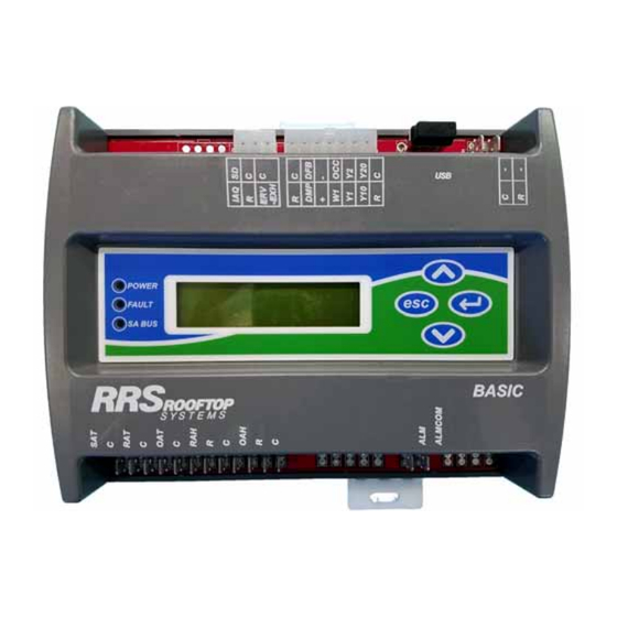
RRS Economizer Controller
FIGURE 1 -
Field-installed economizer accessories with the RRS Econo-
mizer Controller utilize the P12/S12 connector for inter-con-
necting wiring to the 3 through 6 ton units equipped with
Simplicity Lite in the same manner as Honeywell W7212 and
Jade controllers in economizer accessories. Through the
P12/S12 connector, the unit-to-RRS Economizer wiring con-
nections are as follows:
• TB1 to RRS Economizer Controller C pin - Pro-
vides cabinet ground-referenced 24 volts AC com-
mon to power the RRS Economizer Controller,
economizer inputs and outputs
• Simplicity Lite G pin to RRS Economizer Con-
troller R pin - Provides 24 volts AC hot to power
the RRS Economizer Controller, economizer
inputs and outputs when Simplicity Lite operates
the indoor blower
• Simplicity Lite OCC pin to RRS Economizer
Controller OCC pin - 24 volts AC originating from
jumper or thermostat input to the Simplicity Lite
OCC screw terminal, through the Simplicity Lite
OCC output pin to the RRS Economizer Controller
• Simplicity Lite Y1 pin to RRS Economizer Con-
troller Y1 pin - 24 volts AC originating from ther-
mostat input to the Simplicity Lite Y1 screw
terminal, through the Simplicity Lite Y1 output pin
to the RRS Economizer Controller Y1 pin input
indicates there is a first stage cooling request
RRS Economizer Controller Quick Start Guide
RRS Economizer Controller
Quick Start Guide
• RRS Economizer Controller Y1O pin to Sim-
plicity Lite ECON pin - 24 volts AC from the RRS
Economizer Controller Y1O pin output to the Sim-
plicity Lite ECON pin input allows initiation of com-
pressor operation when outdoor conditions are
not suitable for free cooling
Simplicity Lite
Y1
From 24 VAC thermostat input to Simplicity
st
Lite – 1
Stage Cooling Request
G
On with Simplicity Lite blower operation – 24 VAC
Hot for Economizer Controller Power/Inputs/Outputs
OCC
From 24 VAC jumper/thermostat input to
Simplicity Lite – Occupancy Indication
ECON
24 VAC compressor request to Simplicity Lite with
st
1
Stage Cooling Request & Free Clg Avail = No
Simplified Diagram Of RRS Economizer
FIGURE 2 -
Control To 3 Through 6 Ton Unit Wiring
Connections
5292230-USG-B-0718
TB1
24 VAC Common for Economizer
Controller Power/Inputs/Outputs
1
Advertisement

Subscribe to Our Youtube Channel
Related Manuals for Johnson Controls RRS Economizer Controller


Summary of Contents for Johnson Controls RRS Economizer Controller
- Page 1 P12/S12 connector, the unit-to-RRS Economizer wiring con- not suitable for free cooling nections are as follows: • TB1 to RRS Economizer Controller C pin - Pro- vides cabinet ground-referenced 24 volts AC com- 24 VAC Common for Economizer mon to power the RRS Economizer Controller,...
- Page 2 Other than inter-connection to the base unit, the 14-pin con- ries, from the DMP output pin positions the actuator. The +2 nector at the upper edge of the RRS Economizer Controller to +10 volts DC, as configured for 3 through 6 ton economizer...
- Page 3 Simplicity Lite G pin so 24 volts AC power is present From Level 0 of the parameter menu, navigation to Level 1 of to the RRS Economizer Controller C and R pins. A boot-up the menu is done with a press of the (scroll up) (scroll sequence will also begin at the completion of the firmware down) or ...
- Page 4 Level 1 Update Main Menu >Details Unit Unit Level 2 >Setpoints >Setpoints Zone Control Supply Temp Service Level 3 >Damper Min Pos Level 4 Damper Min Pos (Parameter Adjustment) Example Summary FIGURE 7 - RRS Economizer Controller Quick Start Guide...
- Page 5 The range of available selections ended. are shown in red text to the right of set-point and configura- tion parameters listed in the “RRS Economizer Controller A press of the esc (cancel) button retains the previous setting Menu Guide”.
- Page 6 If an incompatible or partitioned flash drive is used, “Backup:FAIL” will be shown on the upper line and an error code following “Backup” will be shown on the lower line of the display instead of the Backup function completion indicators. RRS Economizer Controller Quick Start Guide...
- Page 7 00:00:00 the steps listed below for the Restore function can only use January 1st 1970 (1970-01-01T000000 as shown in the res- the “BackupConfig” restoration file held in controller on-board toration file name). memory. RRS Economizer Controller Quick Start Guide...
- Page 8 The selected restoration file name will then be shown on the the controller firmware is missing or corrupt; this is typically upper line and “Confirm” on the lower line of the display. The corrected by performing the Load Firmware function. RRS Economizer Controller Quick Start Guide...
- Page 9 Firmware Updating And Controller FIGURE 23 - Rebooting With a flash drive having an RRS Economizer Controller firm- ware update file on the top storage level connected to the USB port, the (enter) button is pressed when at (Level 1) “Update”...
- Page 10 Controller clock time begins at 1/1/1970 12:00:00 AM and restarts with each boot-up sequence. Particularly in applica- tions where the indoor fan cycles with heating and cooling RRS Economizer Controller Quick Start Guide...
- Page 11 “ExportTrend” location of the display menu without a compat- ible flash drive connected to the USB port. A press of the esc Table 1: RRS Economizer Controller Trending (cancel) (scroll up) or (scroll down) button will then resume menu navigation.
- Page 12 Self Test Report process. flash drive connected to the USB port. A press of the esc (cancel), (scroll up) or (scroll down) button will then resume menu navigation. RRS Economizer Controller Quick Start Guide...
- Page 13 • [Comp Enable] setting “Yes” The RRS Economizer Controller is powered with unit indoor blower operation; there is output from the Simplicity Lite G pin • [Comp Stages] setting “1” so 24 volts AC power is present to the RRS Economizer Con- troller C and R pins.
- Page 14 All controller functions available 19.2V that follow assume that: ALARM: Outputs Limited Due to Brownout Input V • The RRS Economizer Controller is configured for proper Any additional binary outputs are not permitted interaction with the Simplicity Lite board compressor 16.0V control functions...
- Page 15 • The free cooling changeover method is dual Temp] and [Return Humidity] inputs are available enthalpy if [Outdoor Temp], [Outdoor Humidity], • With [Free Clg Select] set to “Single Enthalpy” – the free cooling changeover method will not advance to dual RRS Economizer Controller Quick Start Guide...
- Page 16 Simplicity Lite Y1 output pin to the RRS Econo- Temp]. Dry bulb is the “standard option” free cooling change- mizer Controller Y1 pin input over method for the RRS Economizer Controller since the included OAT/OAH sensor is the source for [Outdoor Temp] •...
- Page 17 RRS Economizer Controller supply air tempera- ture input and [Excess SAT Stpt] Free cooling operation ends when either: • 24 volts AC input to the RRS Economizer Controller Y1 POWER EXHAUST/ERV FUNCTIONS pin is removed ([Y1-Tstat] indicates “Off”) •...
- Page 18 Excessive Supply Air Temp Cooling been detected; [Supply Temp] falls to or switched off (Simplicity Lite will display flash below the [Excess SAT Stpt] code 11, compressor operation from Y1 ther- mostat/ECON input ends) RRS Economizer Controller Quick Start Guide...
- Page 19 0.0 F Comp 1 Lockout Normal Lo Amb Min Pos Subject to change without notice. Printed in U.S.A. 5292230-USG-B-0718 Copyright © 2018 by Johnson Controls, Inc. All rights reserved. Supersedes: 5292230-USG-A-1016 York International Corporation 5005 York Drive Norman, OK 73069...
Need help?
Do you have a question about the RRS Economizer Controller and is the answer not in the manual?
Questions and answers