Table of Contents
Advertisement
A421 Series Standard Electronic Temperature
Controls
Installation Instructions
A421ABC-x, A421AEC-x,
A421GBF-x, A421GEF-x
Applications
IMPORTANT: Use this A421 Series Electronic
Temperature Control only as an operating control.
Where failure or malfunction of the A421 control could
lead to personal injury or property damage to the
controlled equipment or other property, additional
precautions must be designed into the control
system. Incorporate and maintain other devices, such
as supervisory or alarm systems or safety or limit
controls, intended to warn of or protect against failure
or malfunction of the A421 control.
IMPORTANT: Utiliser ce A421 Series Electronic
Temperature Control uniquement en tant que
dispositif de régulation. Lorsqu'une défaillance ou un
dysfonctionnement du A421 control risque de
provoquer des blessures ou d'endommager
l'équipement contrôlé ou un autre équipement, la
conception du système de contrôle doit intégrer des
dispositifs de protection supplémentaires. Veiller
dans ce cas à intégrer de façon permanente
d'autres dispositifs, tels que des systèmes de
supervision ou d'alarme, ou des dispositifs de
sécurité ou de limitation, ayant une fonction
d'avertissement ou de protection en cas de
défaillance ou de dysfonctionnement du
A421 control.
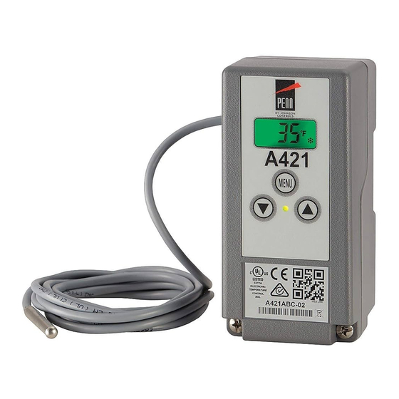
The A421 Series Electronic Temperature Controls are
single-stage, electronic temperature controls with a
single-pole, double-throw (SPDT) output relay.
A421 controls feature a backlit LCD with adjustable
brightness and three-button touchpad interface that
can be set up to restrict user adjustments. An LED
indicates the output relay's On/Off status.
A421 controls have simple On and Off temperature
settings for heating or cooling, an adjustable anti-short
cycle delay, temperature setback, and sensor offset
capability. The temperature control range is
-40 to 212°F or -40 to 100°C.
The A421 controls are available either in Type1
(NEMA), IP20 (CE), high-impact plastic enclosures
suitable for surface or DIN rail mounting (Figure 1)
or in Type 4X (NEMA), IP66 (CE) watertight, corrosion
resistant surface mount enclosures (Figure 2).
A421 Series Standard Electronic Temperature Controls Installation Instructions
Refer to the
QuickLIT website
Dimensions
Figure 1: A421 Control with Type 1 (NEMA),
IP20 Enclosure Dimensions, in. (mm)
Figure 2: A421 Control with Type 4X (NEMA),
IP66 Enclosure Dimensions, in. (mm)
1
Part No. 24-7664-3019, Rev. D
Issued March 2016
for the most up-to-date version of this document.
Advertisement
Table of Contents

Subscribe to Our Youtube Channel
Related Manuals for Johnson Controls Penn A421ABC Series


Summary of Contents for Johnson Controls Penn A421ABC Series
- Page 1 A421 Series Standard Electronic Temperature Controls Installation Instructions Part No. 24-7664-3019, Rev. D Issued March 2016 A421ABC-x, A421AEC-x, A421GBF-x, A421GEF-x Refer to the QuickLIT website for the most up-to-date version of this document. Applications Dimensions IMPORTANT: Use this A421 Series Electronic Temperature Control only as an operating control.
- Page 2 Parts Included Mounting Each A421 Control includes a Johnson Controls/ Observe the following guidelines when locating and PENN® A99 Series temperature sensor. See A99 mounting an A421 control: Series Temperature Sensors, Wiring, and Technical • Ensure that the mounting surface can support the Specifications for more information about A99 sensors.
- Page 3 3. Position the control mounting slots over the screw Wiring heads, and then carefully tighten the mounting WARNING: Risk of Electric Shock. screws to secure the control to the surface. Disconnect or isolate all power supplies 4. When mounting the control on an uneven surface, before making electrical connections.
- Page 4 Table 1: Maximum Recommended Sensor Cable IMPORTANT: When connecting an A99 sensor Lengths and Wire Sizes with a shielded cable to an A421 Control, connect Wire the cable shield drain lead to the COM (common) Maximum Sensor Cable Length Gauge terminal on the sensor and binary input terminal Feet (Meters) block (TB3).
- Page 5 Figure 4: Wiring the A421 Series Controls Using the Same Power Source to Power the Control Operation and Power the Controlled Equipment Table 2: A421 Control Wiring Terminals and Wire Size Information (Part 1 of 2) Terminal Label Description, Function, and Requirements Recommended Block Wire Sizes...
-
Page 6: Setup And Adjustments
Table 2: A421 Control Wiring Terminals and Wire Size Information (Part 2 of 2) Terminal Label Description, Function, and Requirements Recommended Block Wire Sizes Detects a switch closure between the BIN and COM terminals and enables 22 AWG (0.34 mm the selected temperature setback (tSb) value. - Page 7 Three-Button Touchpad Anti-Short Cycle Delay (ASd): Select the minimum time that the output relay remains off (de-energized) The touchpad has three buttons for setup and before the next on-cycle can start. The ASd interval adjustment of the A421 control (Figure 5). See Menu overrides any load demand (On) and does not allow Navigation Guidelines on page 9 for more information the output relay to go on until the selected ASd interval...
- Page 8 Temperature Units (Un): Select the desired • the temperature setback feature is enabled and the temperature scale for your application. Select either the control uses the effective On and OFF setback Fahrenheit (°F) or Celsius (°C) temperature scale. values (On + tSb and OFF + tSb) to control the relay.
-
Page 9: A421 Control Parameter Setup Menus
A421 Control Parameter Setup Menus The A421 temperature controls provide a Basic and an Advanced setup menu that allow you to scroll through the parameter setup codes, view and edit parameter values, and set up your control for your application requirement. -
Page 10: Restricting User Adjustment
To exit the Basic menu and go directly into the Viewing and Changing Values in the Advanced Advanced menu, simultaneously press and , and Menu hold them for 5 seconds. To access the Advanced menu and view and change the parameter values, follow these steps: Advanced Menu The Advanced menu allows you to change the... - Page 11 • The control band (differential) is defined by the On 4. Disconnect power to the control and reposition the and OFF values, and the control band between On jumper to one pin (Figure 10). Reconnect power. and OFF remains fixed (not adjustable). •...
-
Page 12: Fault Codes
5. Press and simultaneously to return to the Troubleshooting Main screen. Fault Codes A421 Series controls display fault codes on the LCD as described in Table 5. Figure 11: Adjusting Temperature in the Restricted Menu Table 5: Fault Codes Defined Fault Code Definition System Status... -
Page 13: Repair Information
A99 sensors, mounting hardware, and other to the control. accessories used to install A421 controls. Contact your nearest Johnson Controls/PENN distributor or sales d. Replace the cover. representative to order these products. e. Check the control settings for proper values. - Page 14 Table 6: A421 Series Standard Electronic Temperature Controls Selection Chart (Part 2 of 2) Product Type Description A421AEC-02C Line-Voltage Type 4X Electronic Temperature Control: Type 4X (NEMA), IP66 watertight enclosure for surface-mount applications. Rated for 120/240 VAC. Includes an A99BB-200C temperature sensor with 6.6 ft (2.0 m) cable.
-
Page 15: Technical Specifications
CFR47, Part 15, Subpart B, Class B Industry Canada (IC) Compliant to Canadian ICES-003, Class B limits Europe: CE Mark – Johnson Controls, Inc. declares that this product is in compliance with the essential requirements and other relevant provisions of the EMC Directive; Low Voltage Directive. - Page 16 -40 to 212ºF or -40 to 100ºC. The performance specifications are nominal and conform to acceptable industry standards. For application at conditions beyond these specifications Johnson Controls, Inc. shall not be liable for damages resulting from misapplication or misuse of its products. United States Emissions Compliance This equipment has been tested and found to comply with the limits for a Class B digital device, pursuant to Part 15 of the FCC Rules.
- Page 17 Johnson Controls® and PENN® are registered trademarks of Johnson Controls, Inc. in the United States of America and/or other countries. All other trademarks used herein are the property of their respective owners. © Copyright 2016 by Johnson Controls, Inc. All rights reserved. A421 Series Standard Electronic Temperature Controls Installation Instructions Published in U.S.A.
Need help?
Do you have a question about the Penn A421ABC Series and is the answer not in the manual?
Questions and answers