Advertisement
Quick Start Guide
SAFETY CHECKLIST
S
urvey the test station. Make sure it is safe & orderly.
A
lways keep unqualified/unauthorized personnel away from the test area.
F
amiliarize yourself with safety protocols in the event of a problem.
E
xercise caution and never touch products or connections during a test.
T
rain operators. Never touch clips directly and always connect the return lead first.
Y
ou should always know when a test is being performed.
WARNING: THIS GUIDE WAS CREATED FOR OPERATORS HAVING SOME FAMILIARITY WITH ELECTRICAL SAFETY
TESTING. AN ELECTRICAL SAFETY TESTER PRODUCES VOLTAGES AND CURRENTS THAT CAN CAUSE HARMFUL
OR FATAL ELECTRIC SHOCK. TO PREVENT ACCIDENTAL INJURY OR DEATH, THESE SAFETY PROCEDURES MUST
BE STRICTLY OBSERVED WHEN HANDLING AND USING A TEST INSTRUMENT. CONTACT US AT
INFO@ARISAFETY.COM FOR MORE INFO ON HOW TO GET TRAINED ON ELECTRICAL SAFETY TESTING.
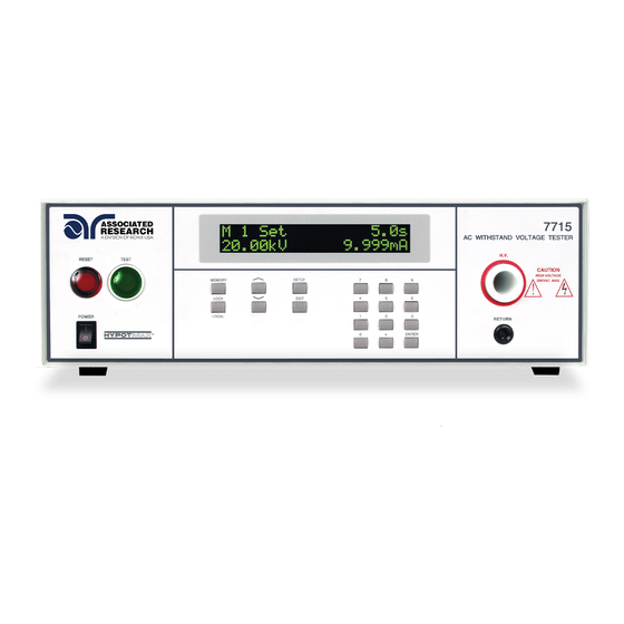
HypotMAX
Models 7705, 7710, 7715, 7720
®
TÜV Rheinland
C
US
Advertisement
Table of Contents

Subscribe to Our Youtube Channel
Related Manuals for IKONIX ASSOCIATED RESEARCH HypotMAX 7705


Summary of Contents for IKONIX ASSOCIATED RESEARCH HypotMAX 7705
- Page 1 Quick Start Guide HypotMAX ® Models 7705, 7710, 7715, 7720 TÜV Rheinland SAFETY CHECKLIST urvey the test station. Make sure it is safe & orderly. lways keep unqualified/unauthorized personnel away from the test area. amiliarize yourself with safety protocols in the event of a problem. xercise caution and never touch products or connections during a test.
- Page 2 FRONT PANEL CONTROLS RESET BUTTON: Resets the instrument. If a failure condition occurs during a test, pressing this button will reset the system, shut off the alarm and clear the failure condition. The Reset button must be pressed before performing another test or changing any of the setup parameters.
- Page 3 FRONT PANEL CONTROLS 12 13 POWER SWITCH: Rocker style power switch with international ON ( | ) and OFF (0) markings. ENTER KEY: Use the ENTER key to accept numeric data for parameter settings. HIGH VOLTAGE OUTPUT TERMINAL: Connector used to attach the high voltage test lead, adapter box high voltage lead or test fixture high voltage lead to the instrument.
- Page 4 BACK PANEL CONTROLS CHASSIS GROUND (Earth) CONNECTION: This terminal should be connected to a good earth ground before operation. CALIBRATION BUTTON: To put the instrument into the calibration mode push this button and turn on the power switch simultaneously. REMOTE SIGNAL INPUT: 9-Pin D-type subminiature male connector for remote control of TEST, RESET, and REMOTE INTERLOCK DISABLE functions, as well as MEMORY SELECTION.
- Page 5 INSTRUMENT SETUP WARNING: LOCATE A SUITABLE TESTING AREA WITH A THREE-PRONG, GROUNDED OUTLET. BE SURE THAT YOUR THREE-PRONG OUTLET HAS BEEN TESTED FOR PROPER WIRING. READ THE SAFETY CHECKLIST OF THIS GUIDE BEFORE STARTING TO TEST. 1. Choose the correct input line voltage on the rear panel of the instrument, either 115VAC or 230VAC.
- Page 6 CHANGING SYSTEM SETTINGS ADDING A NEW TEST Press the SETUP key to progress through the menu of System Parameters. Successive key presses will advance the menu forward. The sequential forward menu items are: PLC Remote Fail Stop Contrast Alarm Smart GFI GPIB address (Displayed with Option 01) BUS Remote...
- Page 7 CHANGING TEST SETTINGS EDITING TEST PARAMETERS If you wish to edit the test parameters, use the Up or Down arrow keys to progress through the test parameters menu. The Down arrow key will advance forward and the Up arrow key will advance backward. The sequence for forward menu items are Voltage, HI-Limit, LO-Limit, Ramp-UP, Dwell Unit, Dwell Time, Ramp-DOWN, Frequency (AC Model), Arc Detect, Arc Sense, Ramp-HI (DC Models), Charge-LO (DC Models), and Connect.
- Page 8 CONDUCTING A TEST Plug the black return lead into the Return terminal on the front panel of the instrument. Then connect the red high voltage lead into the High Voltage terminal on the front panel of the instrument. Attach the black clip-terminated end of the return lead to the dead metal on the chassis of the DUT.
Need help?
Do you have a question about the ASSOCIATED RESEARCH HypotMAX 7705 and is the answer not in the manual?
Questions and answers