Table of Contents
Advertisement
Advertisement
Table of Contents

Related Manuals for IKONIX SCI 290 Series


Summary of Contents for IKONIX SCI 290 Series
- Page 1 Operation & Service Manual Model 294, 295, 296, 297, 298 • V1.05 Model 294 (DC Hipot Tester) Model 295 (AC Hipot Tester) Model 296 (AC/DC Hipot Tester) Model 297 (AC/DC Hipot With IR Tester) Model 298 (500VA AC Hipot Tester) Item 99-10813-01 Printed May 21, 2020 RoHS 2...
- Page 2 DECLARATION OF CONFORMITY Manufacturer: SCI A Division of Ikonix USA Address: 28105 N. Keith Drive Lake Forest, IL 60045 Product Name: SCI 290 Series Model Number: 294, 295, 296, 297 Conforms to the following Standards: Safety: UL 61010-1:2012 CAN/CSA-C22.2 NO. 61010-1-12...
- Page 3 DECLARATION OF CONFORMITY Manufacturer: SCI A Division of Ikonix USA Address: 28105 N. Keith Drive Lake Forest, IL 60045 Product Name: SCI 290 Series Model Number: 298 (500VA) Conforms to the following Standards: Safety: UL 61010-1:2012 CAN/CSA-C22.2 NO. 61010-1-12 EMC:...
- Page 4 Warranty Policy SCI certifies that the tester listed in this manual meets or exceeds published manufacturing specifications. This tester was calibrated using standards that are traceable to the National Institute of Standards and Technology (NIST). Your new tester is warranted to be free from defects in workmanship and material for a period of (1) year from date of shipment. SCI recommends that your tester be calibrated on a twelve-month cycle.
-
Page 5: Table Of Contents
TABLE OF CONTENTS SAFETY PRECAUTIONS REQUIRED FOR HIGH VOLTAGE TESTING! ..................6 Front Panel Controls ..................................7 Rear Panel Controls ..................................8 Setup Instructions ..................................11 Power-Up Sequence ..................................11 Getting To Know Your Tester ......................................12 1. Working With Memories ......................................12 2. Perform Test Screen ........................................12 3. -
Page 6: Safety Precautions Required For High Voltage Testing
Safety Precautions GENERAL This product and its related documentation must be reviewed for familiarization with safety markings and instructions before operation. This product is a Safety Class I tester (provided with a protective earth terminal). Before applying power verify that the tester is set to the correct line voltage (115 or 230) and the correct fuse is installed. INSTRUCTION MANUAL SYMBOL. -
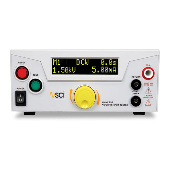
Page 7: Front Panel Controls
Front Panel Controls RESET BUTTON - This is a momentary contact switch used to reset the tester. If an out-of-range reading is detected during a test, the red failure lamp within the button will light. To reset the system for the next test, press and release this button. -
Page 8: Rear Panel Controls
Rear Panel Controls CALIBRATION ENABLE KEY - To enter the calibration mode press this key while the tester is being powered ON. USB CONNECTOR - Optional USB port for serial communication. Refer to Option 03 in the Options section. SIGNAL OUTPUT - 9 pin D subminiature female connector for monitoring PASS, FAIL, and PROCESSING output relay signals. - Page 9 Front Panel Controls Model 298 RESET BUTTON - This is a momentary contact switch used to reset the tester. If an out-of-range reading is detected during a test, the red failure lamp within the button will light. To reset the system for the next test, press and release this button.
- Page 10 Rear Panel Controls Model 298 OPTIONAL CONTINUITY CHECK PORT - Provides the connection for checking ground continuity. OPTIONAL RETURN PORT - Provides the return connection for the leakage current. OPTIONAL HIGH VOLTAGE OUTPUT PORT - Use this jack for the connection of the detachable high voltage test lead or the adapter box high voltage connector.
-
Page 11: Setup Instructions
2. Connect the power input plug into its socket on the rear panel of the tester. The SCI 290 series of testers has an automatic input voltage range selection. 3. Connect the male end of the plug to the grounded AC outlet. -
Page 12: Getting To Know Your Tester
1. Working with Memories The SCI 290 series of testers are equipped with 5 memory programs numbered 1 through 5. Each memory can be connected sequentially to the next consecutive memory. Only one test type can be selected for each memory location. -
Page 13: Selecting Memory
3. Selecting Memory GO BACK TO THE MAIN MENU START Turn the yellow rotary knob to When BACK is selected. Press the Main Menu scroll to BACK in order to return rotary knob. You will be returned to the Main Menu. to the Main Menu. -
Page 14: Setting An Ac Hipot Test
4. Setting an AC Hipot Test PROGRAM A MEMORY: TYPE AC START When TYPE is selected. Press the Turn the yellow rotary knob to Turn the rotary knob to change scroll to desired parameter to rotary knob to edit the Test Type. the Test Type: ACW, DCW or IR. - Page 15 PROGRAM A MEMORY: CHANGE HI LIMIT START When HI-L is selected. Press the Turn the yellow rotary knob to Turn the rotary knob to change scroll to desired parameter to rotary knob to edit the HI-Limit. the HI-Limit setting for each digit. edit HI-L.
- Page 16 PROGRAM A MEMORY: CHANGE RAMP START Turn the yellow rotary knob to When RAMP is selected. Press the Turn the rotary knob to change scroll to desired parameter to rotary knob to edit the Ramp Time. the Ramp Time for each digit. edit RAMP.
- Page 17 PROGRAM A MEMORY: CHANGE CONTINUITY START Turn the yellow rotary knob to When CONT is selected. Press the Turn the rotary knob to change the Continuity setting: ON or OFF. scroll to desired parameter to rotary knob to edit the Continuity. edit CONT.
- Page 18 PROGRAM A MEMORY: CHANGE FREQUENCY START Turn the yellow rotary knob to When FREQ is selected. Press the Turn the rotary knob to change the rotary knob to edit the Frequency. Frequency setting: 50Hz or 60Hz. scroll to desired parameter to edit FREQ.
-
Page 19: Setting A Dc Hipot Test
5. Setting a DC Hipot Test The DC Hipot test can be programmed into any of the 5 memory locations in a similar manner as the AC Hipot test. From the main menu, select the memory location that you desire to program with the DC Hipot test. PROGRAM A MEMORY: TYPE DC START When TYPE is selected. - Page 20 PROGRAM A MEMORY: CHANGE HI LIMIT START When HI-L is selected. Press the Turn the yellow rotary knob to Turn the rotary knob to change scroll to desired parameter to rotary knob to edit the HI-Limit. the HI-Limit setting for each digit. edit HI-L.
- Page 21 PROGRAM A MEMORY: CHANGE RAMP START When RAMP is selected. Press the Turn the yellow rotary knob to Turn the rotary knob to change scroll to desired parameter to rotary knob to edit the Ramp Time. the Ramp Time for each digit. edit RAMP.
- Page 22 PROGRAM A MEMORY: CHANGE CONTINUITY START Turn the yellow rotary knob to When CONT is selected. Press the Turn the rotary knob to change scroll to desired parameter to rotary knob to edit the Continuity. the Continuity setting: ON or OFF. edit CONT.
-
Page 23: Setting An Ir Test
PROGRAM A MEMORY: CHANGE CONNECT START When CONN is selected. Press the Turn the yellow rotary knob to Turn the rotary knob to change scroll to desired parameter to rotary knob to edit the Connect the Connect setting: ON or OFF. edit CONN. - Page 24 PROGRAM A MEMORY: CHANGE VOLTAGE IR START Turn the yellow rotary knob to When VOLT is selected. Press the Turn the rotary knob to change scroll to desired parameter to rotary knob to edit the Voltage. the Voltage setting for each digit. edit VOLT.
- Page 25 PROGRAM A MEMORY: CHANGE LO LIMIT IR START When LO-L is selected. Press the Turn the yellow rotary knob to Turn the rotary knob to change scroll to desired parameter to rotary knob to edit the LO-Limit. the LO-Limit setting for each digit. edit LO-L.
- Page 26 PROGRAM A MEMORY: CHANGE DELAY IR START Turn the yellow rotary knob to When DLAY is selected. Press the Turn the rotary knob to change scroll to desired parameter to rotary knob to edit the Delay Time. the Delay Time for each digit. edit DLAY.
-
Page 27: System Parameter Descriptions
System Parameter Descriptions System Parameter Setting Description Allows the user to initiate a test through the REMOTE INPUT on the rear panel of the tester. If PLC Remote = ON the front panel TEST button is disabled and a test may PLC Remote ON/OFF only be started through the rear panel I/O. -
Page 28: Setting System Parameters
Setting System Parameters EDIT SECURITY SETTINGS START When SCTY is selected. Press the Default screen. Turn the yellow rotary knob to scroll to SCTY to edit Security rotary knob to enter the Security settings. settings. The options will blink. Turn rotary knob to change the Press the rotary knob to select Enter a PIN number for the Security Security settings: OFF, RUN or... - Page 29 EDIT PLC REMOTE SETTINGS START Home screen. Turn the yellow rotary knob to When PLC is selected. Press the scroll to PLC to edit the PLC rotary knob to enter the PLC settings. settings. The options will blink. Turn rotary knob to change the Press the rotary knob to select You will be returned to the PLC settings: ON or OFF.
-
Page 30: Using The Display
Using the Display Test Mode Displays Test Mode Display Test Type Description AC/DC Hipot & IR Displayed when the test voltage is ramping up from 0.0 VAC/VDC to full test voltage. AC/DC Hipot Displayed when the test voltage has reached full potential. Dwell is the amount of time the potential is held at the set value. -
Page 31: Error Messages
Failure Mode Display* Test Type Description DC Hipot Displayed if the leakage current does not exceed the low limit setting. DC Hipot Displayed if there is a short circuit in the DUT during the test. DC Hipot Displayed if the leakage current exceeds the metering range and either a short or flashover has occurred during the test. -
Page 32: Reviewing Test Results For Multistep Sequences
Reviewing Test Results for Multi-step Sequences After the test is performed, the test results will be indicated on the front panel display. Pass: If the DUT passes the test, you will hear a short audible beep and the display will indicate the test result. Fail: If a failure occurs, you will hear a long audible alarm and the red flashing indicator will light up. -
Page 33: Signals On Remote I/O
Signals on Remote I/O REMOTE INPUT/OUTPUT Remote Output Output Signal Pins Description PASS 1 and 2 The relay contact closes after detecting that the device under test passed all tests. The connection is opened when the next test is initiated or the reset function is activated. -
Page 34: Using The Tester Accessories
Using the Tester Accessories NEVER CONNECT THE ADAPTER BOX OR TEST LEADS TO THE TESTER WHILE THE HIGH WARNING VOLTAGE OUTPUTS ARE ENERGIZED. Using the Test Leads Plug the black ground return lead (P/N 102-069-904) into the Return terminal located on the front panel of the tester. Plug the high voltage lead (P/N 102-055-913) into the H.V. -
Page 35: Using The Adapter Box
Using the Adaptor Box The adapter box is an optional accessory and is not provided as standard equipment with the 290 Series. If you would like to acquire an adapter box for use with your tester, please contact Slaughter Company Inc. using the contact information provided in the Safety section of this manual. -
Page 36: Appendix A - Installation And Test Operator Information
Appendix A - Installation and Test Operator Information Installation 1. Unpacking and Inspection Your tester was shipped in a custom foam insulated container that complies with ASTM D4169-92a Assurance Level II Distribution Cycle 13 Performance Test Sequence. If the shipping carton is damaged, inspect the contents for visible damage such as dents, scratches, or broken meters. If the tester is damaged, notify the carrier and the Slaughter Company customer support department immediately. -
Page 37: Preparation For Use
4. Preparation for Use Power Requirements and Line Voltage Selection This tester requires a power source of either 115 volts AC ± 10%, 47-63 Hz single phase or CAUTION 230 volts AC ±10%, 47-63 Hz single phase. In addition, please be sure the correct fuse is selected and installed while the tester is in the off position. -
Page 38: Storage And Shipment
Storage and Shipment Environment This tester may be stored or shipped in environments with the following limits: Temperature ................-40° - 167° F (-40° - 75°C) Altitude .................. 50,000 feet (15,240 meters) The tester should also be protected against temperature extremes which may cause condensation within the tester. Packaging Contact our customer support department (1-847-932-3662) for an RMA (return materials authorization) number. -
Page 39: Test Operator And Safety Considerations
Test Operator Safety Considerations 1. Qualifications This tester generates voltages and currents which can cause harmful or fatal electric shock and must only be operated by a skilled worker trained in its use. The operator should understand the electrical fundamentals of voltage, current, and resistance. 2. -
Page 40: Test Station
6. Test Station Location Select an area away from the main stream of activity which employees do not walk through in performing their normal duties. If this is not practical because of production line flow, then the area should be roped off and marked for HIGH VOLTAGE TESTING. -
Page 41: Appendix B - 290 Series Tester Specifications
Appendix B - 290 Series Tester Specifications Unless otherwise stated, accuracies are relative to a laboratory standard measurement. Why use the term “Counts”? Slaughter publishes some specifications using COUNTS which allows us to provide a better indication of the tester’s capabilities across measurement ranges. - Page 42 LO-Limit Range: 0.00 – 12.00 mA AC Resolution: 0.01 mA Accuracy: ± (2% of setting + 2 counts) Range: 0.00 – 5.00 mA DC Resolution: 0.01 mA Accuracy: ± (2% of setting + 2 counts) Model 298 Range: 0.00 – 100 mA AC (Model 298) Resolution: 0.01 mA Accuracy:...
- Page 43 Resistance Display Range: 1 - 1000 MΩ (4 Digit, Auto Ranging) Resolution: 100- 499 VDC 500 – 1000 VDC MΩ MΩ MΩ 0.001 1.000 – 1.999 1.000 – 9.999 0.01 2.00 - 19.99 10.00 - 99.99 20.0 – 1000 100.0 – 1000 Accuracy: ±...
-
Page 44: Appendix C - 290 Series Options
Appendix C - 290 Options Introduction This section contains a list and descriptions of available factory installed options at the time of this printing. The list of options contains an option code number which can be referenced on the model option label on the rear panel of the unit when options are present. - Page 45 This option may be added as a serial type communication protocol. This option provides all of the function control of the USB interface. The Type B USB connector labeled “USB” is for connection of the SCI 290 Series Testers to any compatible PC. When selecting USB Interface, the protocol for interfacing and communicating with a PC can be found in Appendix D: Remote Bus Interface: USB of this manual.
- Page 46 Option 06 - 3mA AC/DC Current Limitation (all models) This option limits the maximum current capability of the tester to 3mA AC or DC. The following specifications table is applicable when this option is installed in the tester: AC WITHSTAND VOLTAGE Settings Hi-Limit AC current, mA Range:...
- Page 47 Option 07 – Pulse Mode (Model 295 only) This option allows the tester to perform repeated testing upon a failure. The tester will automatically reset after failure for continuous testing. The testing time will not be restarted when automatic reset for continuous testing. With this option installed on the tester an additional test parameter PULS will be available in the menu.
- Page 48 Option 08 – Push to Test Mode With this option installed an extra parameter called HOLD appears in the ACW test setup. When HOLD is set to ON, the DWELL parameter in the test setup disappears. This allows the user to press and hold the TEST button to execute the test and run it continuously or for any desired time.
-
Page 49: Appendix D - Remote Bus Interface: Usb
Appendix D - Remote BUS Interface: USB This section provides information on the proper use and configuration of bus remote interface. The USB remote interface is optional on all 290 Series models. Please see the OPTIONS section of the manual for details. USB Interface This interface provides all of the control commands and parameter setting commands. - Page 50 Memory Location Edits and Companion Queries The following commands are used to create or modify Test Setup at each Memory Locations. Command Description Value FL <memory location number> Load Test Located at Memory location number = 1-5 Memory Location Query Memory Location Add ACW Test Add DCW Test...
- Page 51 Test Parameter Editing Commands These commands are used to modify the test parameter within each memory. These commands require a parameter value to be included with the command. The companion query command will read the parameter. The writing of the parameter requires that the unit not be included with the value, only the numeric value should be included with the command.
- Page 52 System Parameter Editing Commands and Companion Queries These commands are used to modify the system parameters for the tester. These commands require a parameter value to be included with the command. Command Name Value SPR {1|0} PLC Remote ON/OFF 1=On, 0=Off SPR? SEC <...
- Page 53 RI? - Read the remote Interlock input signal. When the remote Interlock has to be activated by opening the contacts the query will return a value of 1 to indicate the tester is in the Interlock state and will not be able to generate output voltage or current. RDM? - Read the remote Interlock input signal.
- Page 54 *ESR? Standard Event Status Register Query BIT 0, 01H,(1) Operation Complete BIT 1,02H,(2) Not Used BIT 2,04H,(4) Query Error BIT 3,08H,(8) Device Error BIT 4,10H,(16) Execution Error BIT 5,20H,(32) Command Error BIT 6,40H,(64) Not Used BIT 7,80H,(128) Power On *ESE <value> Standard Event Status Enable Command value = 0 - 255 *ESE?
- Page 55 *ESE? - Queries the Standard Event enable register. Returns the decimal value of the binary-weighted sum of bits. *STB? - Read the Status Byte. Returns the decimal value of the binary-weighted sum of bits. *SRE <value> - Service Request enable register controls which bits from the Status Byte should be use to generate a service request when the bit value = 1.
-
Page 56: Appendix E - Replacement Parts List - 290 Series
Appendix E - Replacement Parts List - Model 290 Part Number Reference Description Designator Supplied Accessories 99-10020-01 Fuse 3.15A 250V Fast-Blow 20mm 99-10040-01 Interlock Connector 102-069-904 Cable Assembly Return Lead 102-055-913 High Voltage Lead 125-013-001 Cable Input Cordset USA 99-10164-01* Cable Input Cordset USA 99-10797-01 USB Cable... -
Page 57: Appendix F - Service And Maintenance
Appendix F - Service and Maintenance User Service To prevent electric shock do not remove the tester cover. There are no user serviceable parts inside. Routine maintenance or cleaning of internal parts is not necessary. Any external cleaning should be done with a clean dry or slightly damp cloth. Avoid the use of cleaning agents or chemicals to prevent any foreign liquid from entering the cabinet through ventilation holes or damaging controls and switches. -
Page 58: Appendix G - Calibration Procedure
Appendix G – Calibration Procedure This tester has been fully calibrated at the factory in accordance to our published specifications. It has been calibrated using standards with accuracies traceable to the National Institute of Standards and Technology (NIST). You will find in this manual a copy of the “Certificate of Calibration”. - Page 59 Turn and press the rotary knob to enter the reading of the standard AC Voltmeter into the tester. Once all digits are entered the tester will advance to the next calibration point. Then the display will show a value around 8 Volts. Turn and press the rotary knob to enter the reading of the standard AC Voltmeter into the tester.
- Page 60 Press the TEST button again on the front panel. The tester will provide around 100VAC on the output connectors and the display will show: Then the display will show a value around 100 Volts. Turn and press the rotary knob to enter the reading of the standard AC Voltmeter into the tester. Once all digits are entered the tester will advance to the next calibration point.
- Page 61 Then press the Test button on the front panel. The tester will begin outputting high voltage on the output connectors. Then the display will show a value similar to that of the standard. Turn and press the rotary knob to enter the reading of the standard AC Ammeter into the tester. Once all digits are entered the tester will advance to the next calibration point.
- Page 62 Then the display will show a value similar to that of the standard. Turn and press the rotary knob to enter the reading of the standard AC Ammeter into the tester. Once all digits are entered the tester will advance to the next calibration point. Then press the Test button on the front panel.
Need help?
Do you have a question about the SCI 290 Series and is the answer not in the manual?
Questions and answers