Table of Contents
Advertisement
Quick Links
Advertisement
Table of Contents

Subscribe to Our Youtube Channel
Related Manuals for IKONIX LVB-2


Summary of Contents for IKONIX LVB-2
- Page 1 LVB-2 INSTRUCTION SHEET Leakage Current Verification Box V 1.03 | 1.2019...
-
Page 2: Declaration Of Conformity
The product herewith complies with the requirements of the Low Voltage Directive 2014/35/EU and the EMC Directive 2014/30/EU. The technical file and other documentation are on file with Associated Research, Inc. Joseph Guerriero President Associated Research, Inc. Lake Forest, Illinois USA March 13, 2020 © Ikonix USA... -
Page 3: Connector Terminal
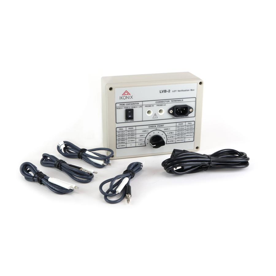
LVB-2 Instruction Sheet LVB-2 Technical Specifications INPUT CONNECTOR TERMINAL VOLTAGE L, N, GND 277V MAC through LLT Tester AC Socket PROBE L, N, GND, PH, PL PH, PL Alden Connector PROBE CONFIGURATION PROBE CONFIGURATION SWITCH GND - LINE ON/OFF by 10A power switch... -
Page 4: Test Points
LVB-2 Instruction Sheet GENERAL CONTINUED TEST POINTS TEST CONDITION SPECIFICATION FAIL 30kΩ 1. LLT: 132VAC, 2000uA High Limit 2. Maximum Voltage 277VAC 3. Ground = Open, Neutral = Closed, Reverse = Off PASS 350kΩ 1. LLT: 132VAC, 500uA High Limit 2. -
Page 5: Standard Accessories
LVB-2 Instruction Sheet GENERAL CONTINUED TEST POINTS TEST CONDITION SPECIFICATION PASS 2.97MΩ 1. LLT: 264VAC, 100uA High Limit 2. Maximum Voltage 277VAC 3. Ground = Open, Neutral = Closed, Reverse = Off FAIL 1.47MΩ 1. LLT: 264VAC, 100uA High Limit 2. -
Page 6: Maintenance
à la LVB-2 WARNING The LVB-2 works with test voltages and currents which can cause harmful or fatal electric shock. To prevent accidental injury or death, these safety procedures must be strictly observed when handling and using the test instrument. - Page 7 • Verifying the three probe configurations of the instrument (G-L, PH-L and PH-PL) are functioning properly. The LVB-2 consists of loads based on the 132V/264V test voltages and failure limits listed in the IEC60601-1 test standard for different types of leakage tests.
- Page 8 LVB-2 Instruction Sheet The LVB-2 load box consists of resistors designed to induce a PASS FAIL condition: • The Check Point knob position determines which resistor is set in the LVB-2 • Each check point has a PASS and FAIL condition.
-
Page 9: Instrument Connections
Test Setup To setup a test, connect the DUT outputs (L, N and G) of the leakage instrument to the line cord connector on the LVB-2. The two probe connections will also need to be made between the instrument and the LVB-2 for the verification of additional leakage test types Program a test sequence based on the parameters listed on the test box for each load type.
Need help?
Do you have a question about the LVB-2 and is the answer not in the manual?
Questions and answers