Table of Contents
Advertisement
Quick Links
Instructions/Parts List
Sanitary, 3A, Flapper Check, and
Poultry Series Diaphragm Pumps
Models SPSG15, SPSG30, SP3G30, SPFC30, SPPP30
For use in sanitary applications. For professional use only.
See Models on page 3 for model numbers, descriptions, and compliance approvals.
120 psi (0.8 MPa, 8 bar) Maximum Fluid Working Pressure
120 psi (0.8 MPa, 8 bar) Maximum Air Input Pressure
Important Safety Instructions. Read
all warnings and instructions in this
manual. Save these instructions.
See page 2 for Table of Contents.
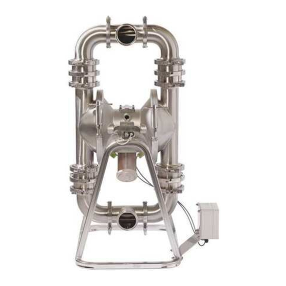
Model SP3G30SSE Shown
3A4552A
EN
TI8760b
Advertisement
Table of Contents

Related Manuals for Standard Pump SPSG15 Series


Summary of Contents for Standard Pump SPSG15 Series
- Page 1 Instructions/Parts List Sanitary, 3A, Flapper Check, and Poultry Series Diaphragm Pumps 3A4552A Models SPSG15, SPSG30, SP3G30, SPFC30, SPPP30 For use in sanitary applications. For professional use only. See Models on page 3 for model numbers, descriptions, and compliance approvals. 120 psi (0.8 MPa, 8 bar) Maximum Fluid Working Pressure 120 psi (0.8 MPa, 8 bar) Maximum Air Input Pressure Important Safety Instructions.
-
Page 2: Table Of Contents
Contents Models ........3 Check Valve Repair ..... . 19 Warnings . -
Page 3: Models
Models Models Compliance Model Connection Description Approvals SP3G30SSE Flange Sanitary Diaphragm Pump 44-03 SPSG30SSS Flange Sanitary Ball Check Pump SPFC30SSS Flange SPFC30SSB Flange SPPP30SSS Flange Sanitary Flapper Check Pump II 2 G c T6 SPPP30SSB Flange SPPP30SSF Flange SPSG15SSE Flange SPSG30SSE Flange Sanitary Ball Check Pump... -
Page 4: Warnings
Warnings Warnings The following warnings are for the setup, use, grounding, maintenance, and repair of this equipment. The exclama- tion point symbol alerts you to a general warning and the hazard symbol refers to procedure-specific risk. When these symbols appear in the body of this manual, refer back to these warnings. Additional, product-specific warnings may be found throughout the body of this manual where applicable. - Page 5 Warnings WARNING EQUIPMENT MISUSE HAZARD Misuse can cause death or serious injury. • Do not operate the unit when fatigued or under the influence of drugs or alcohol. • Do not exceed the maximum working pressure or temperature rating of the lowest rated system component.
-
Page 6: Installation
Contact your Standard Pump distributor for assistance in planning a system to suit your needs. • Always use genuine Standard Pump parts and accessories. -
Page 7: Mountings
Installation a. Install an air regulator (C) and gauge to control the fluid pressure. The fluid outlet pressure will be the same as the setting of the air regulator. b. Locate one bleed-type master air valve (B) close to the pump and use it to relieve trapped air. -
Page 8: Fluid Outlet Line
Installation Fluid Outlet Line 1. Use flexible, grounded fluid hoses (L) where possible. 2. For best sealing results, use a standard tri-clamp A fluid drain valve (J) is required to relieve pressure in sanitary gasket of a flexible material such as EPDM, the hose if it is plugged. -
Page 9: Changing The Orientation Of The Fluid Inlet And Outlet Ports
Installation Changing the Orientation of the Fluid Inlet and Outlet Ports The pump is shipped with the ports facing the same direction. To reorient the ports into any position: 1. Remove the clamps (130) holding the inlet and/or outlet tee to the elbows. 2. -
Page 10: Air Exhaust Ventilation
Installation Air Exhaust Ventilation The air exhaust port is 3/4 npt(f). Do not restrict the air exhaust port. Excessive exhaust restriction can cause erratic pump operation. To provide a remote exhaust: Be sure the system is properly ventilated for your type 1. -
Page 11: Operation
Operation Operation Pressure Relief Procedure 3. Place the suction tube (if used) in fluid to be pumped. NOTE: If fluid inlet pressure to the pump is more than 25% of the outlet working pressure, the ball check valves will not close fast enough, resulting in inefficient Trapped air can cause the pump to cycle pump operation. -
Page 12: Maintenance
Maintenance Maintenance Lubrication 4. Using a brush or other C.O.P. methods, wash all product contact pump parts with an alkaline deter- The air valve is designed to operate unlubricated. If gent at the manufacturer’s recommended tempera- lubrication is desired, every 500 hours of operation (or ture and concentration. -
Page 13: Preventive Maintenance Schedule
Maintenance Preventive Maintenance Schedule Establish a preventive maintenance schedule based on The following is a list of recommended maintenance the pump’s service history. This is especially important procedures and frequencies. Maintenance must be per- for prevention of spills or leakage due to diaphragm formed by trained personnel per the established failure. -
Page 14: Troubleshooting
Troubleshooting Troubleshooting • Follow the Pressure Relief Procedure, page 11, before checking or servicing the equipment. • Check all possible problems and causes before disassembling the pump. CAUSE SOLUTION PROBLEM Pump cycles at stall or fails to hold Worn check valve balls (541) or Replace. - Page 15 Troubleshooting PROBLEM CAUSE SOLUTION Leak in inlet or outlet sanitary fit- Loose sanitary clamp. Tighten clamp. ting. Damaged or worn gasket. Replace gasket. Misalignment of inlet/outlet hose or Use flexible hoses at pump inlet pipe. and outlet. Gasket does not seal. Use a standard sanitary gasket of flexible material such as EPDM, Buna-N, fluoroelastomer, or silicon.
-
Page 16: Service
Service Service Repairing the Air Valve 3. Move the valve carriage (105) to the center position and pull it out of the cavity. Using a needle-nose pli- ers, pull the pilot block (116) straight up and out of Tool Required the cavity. - Page 17 Service 5. Inspect the valve plate (108) in place. If damaged, Reassembly use a Torx (T20) screwdriver or 7 mm (9/32 in.) 1. If you replaced the bearings (112, 117), reinstall as socket wrench to remove the three screws (103). explained on page 26.
- Page 18 Service 6. Grease the lower face of the pilot block (116) and 9. Align the valve gasket (104) and cover (102) with install so its tabs snap into the grooves on the ends the six holes in the center housing (101). Secure of the pilot pins (114).
-
Page 19: Check Valve Repair
Service Check Valve Repair Disassembly 132a Reference numbers with an asterisk (*) are replacement *240 parts. For a complete list of replacement parts see 129* Parts, page 29 and following. 132c *240 *541 *240 132b 1. Follow the Pressure Relief Procedure, page 11. Disconnect all hoses. - Page 20 Service For Sanitary Ball Check pumps: remove ball gasket For Flapper Check pumps: remove gasket (240). (242) and ball (541). Remove lower clamp (132b), Remove middle clamp (132c) and housing (252). seat (233), and gasket (240). Clean all parts and Remove middle gasket (240), and flapper valve inspect for wear or damage.
-
Page 21: Standard Diaphragm Repair
Service 6. Disassemble the outlet manifold. Remove clamps Standard Diaphragm Repair (130), tee (339), gasket (129), and elbow (128). NOTE: See page 24 for overmolded diaphragms, Clean all parts and inspect for wear or damage. including all 3A diaphragms. Replace parts as needed. Tools Required 7. - Page 22 Service 4. With both fluid covers removed, using two 5/8 in. 8. Inspect the diaphragm shaft (121) for wear or wrenches hold the wrench flats (Y) on the plates of scratches. If it is damaged, inspect the bearings each diaphragm assembly and loosen. One dia- (117) in place.
- Page 23 Service Reassembly 1. Install the shaft u-cups (110) so the lips face out of Screw assembled diaphragm assembly into shaft the housing (101). Lubricate the u-cups. See Reas- (121) and hand tighten. sembly of Bearing, page 26. 4. Grease the length of the diaphragm shaft (121), and slide it through the housing (101).
-
Page 24: 3A/Overmolded Diaphragm Repair
Service 3A/Overmolded Diaphragm Repair NOTE: If your pump uses standard diaphragms, see 6. Pull the opposite diaphragm assembly and shaft page 21. (121) out of the center housing (101). Hold the shaft flats with a 19 mm open end wrench and remove the Tools Required diaphragm and air side plate from the shaft. - Page 25 Service Reassembly NOTICE Do not deform the diaphragm manually. The dia- phragm needs uniform pressure to deform properly. To reduce the risk of serious injury, including amputation, do not put your fingers or hand between 6. Assemble the fluid cover (234) and clamp (135) so the air cover and the diaphragm.
-
Page 26: Bearing And Air Gasket Removal
Service Bearing and Air Gasket Removal Tools Required • Torque wrench • 10 mm socket wrench • Bearing puller • O-ring pick • Press, or block and mallet 110* Disassembly TI4731a NOTE: Do not remove undamaged bearings. . 24 8. If you removed the diaphragm shaft bearings (117) reach into the center housing (101) with an o-ring pick and hook the u-cups (110), then pull them out of the housing. - Page 27 Service 4. Align the new air cover gasket (119) so the pilot pin 7. Reassemble the ball check valves and manifolds as (114) protruding from the center housing (101) fits explained on page 19. through the proper hole in the gasket TI4730a .
-
Page 28: Pump Matrix
Pump Matrix Pump Matrix Sanitary Series Stainless Steel Pumps Model Inlet and Center Section Seat Balls Diaphragm Number Outlet (inch) 2-inch Sanitary SPSG15SSE 2 x 2 Stainless Steel Stainless Steel PTFE Overmolded EPDM Series SPSG30SST 3 x 3 Overmolded PTFE 3-inch Sanitary SPSG30SSS 3 x 3... -
Page 29: Parts Drawing, Fluid Section
Parts Drawing, Fluid Section Parts Drawing, Fluid Section 129* 339* *240 Sanitary Ball Check Sanitary Diaphragm Assembly Valve Assembly 444 143 446* 447* *242 *240 *541 *240 *240 TI7644a TI4729c 446* 446a* *240 Flapper Check Valve Assembly *240 *240 *240 *240 Apply a high-strength thread locker to attach the screw to the diaphragm, if needed. -
Page 30: Parts List, Fluid Section
Parts List, Fluid Section Parts List, Fluid Section Pump Configuration Inlet and Outlet Ref. Part No. Description Ref. Part Description Models SPXX30 Models SPXX30 3A Approved Ball Check Pump Tri-clamp tee 400-308 CLAMP, 4 in. 400-300 ELBOW 400-319 SEAT 400-321 GASKET, sanitary, EPDM, 3 in. 4 400-303 COVER, fluid 400-273 CLAMP, sanitary, 3 in. -
Page 31: Diaphragm Material
Parts List, Fluid Section Diaphragm Material Check Ball Material Ref. Part Description Ref. Part Description Models SPXX30 Models SPXX30 Kit 400-071, 3A Approved, EPDM, Overmolded; includes 110 and 446 3A Approved, PTFE 400-211 U-CUP 541*† 200-296 BALL 446*† DIAPHRAGM ASSY Flapper check 400-297 PLATE, diaphragm (air side) -
Page 32: Parts Drawing, Air Section And Stand
Parts Drawing, Air Section and Stand Parts Drawing, Air Section and Stand 104 115 116 105 110 108 110 Apply medium strength adhesive to outside surface of piston bearing and inside surface of center housing bore. TI4680c Apply a medium strength thread locker to screw threads and torque to 130-150 in-lbs (14.6-16.9 N•m). -
Page 33: Parts List, Air Section And Stand
Parts List, Air Section and Stand Parts List, Air Section and Stand Air Section - All Models Leak Detector and Pump Stand Qty. Ref. Part Description Ref. Part Description 400-329 HOUSING, center 3A Approved, Leak Detector and Pump Stand SPXX30 400-330 HOUSING, cover 400-100... -
Page 34: Accessories
Accessories Accessories SPXX30 Conversion Kits 400-100 Leak Detector 400-080 3A Approved Ball Check Conversion Kit Sensor and control package that monitors the dia- phragm condition. In case of diaphragm failure, the con- Converts flapper check valve to 3A ball check valve. trol will provide an audible alarm and relay contacts for Includes four seats and four ball stops. -
Page 35: Model Spsg15 Dimensional Drawing
Model SPSG15 Dimensional Drawing Model SPSG15 Dimensional Drawing 24.9 in. (632.5 mm) 35.8 in. (909.3 mm) 8.6 in. (218.4 mm) 23.6 in. 17.0 in. (594.4 mm) (431.8 mm) TI8778a TI8777a 23.5 in. (596.9 mm) 3A4552A... -
Page 36: Model Spsg15 Technical Data
Model SPSG15 Technical Data Model SPSG15 Technical Data Maximum fluid working pressure ....120 psi (0.8 MPa, 8 bar) Air pressure operating range ..... . 20-120 psi (0.14-0.8 MPa, 1.4-8 bar) Maximum air consumption . -
Page 37: Model Spsg15 Performance Chart
Model SPSG15 Performance Chart Model SPSG15 Performance Chart Test Conditions: Pump tested in water with inlet submerged To find Fluid Outlet Pressure To find Pump Air Pressure (psi/MPa/bar) at a specific fluid flow (gpm/lpm) and (scfm or m /min) at a specific fluid flow (gpm/lpm) and operating air pressure (psi/MPa/bar): operating air pressure (psi/MPa/bar): 1. -
Page 38: Model Spxx30 Dimensional Drawing
Model SPXX30 Dimensional Drawing Model SPXX30 Dimensional Drawing 3A Ball Check Valve Pumps 28.4 in. 37.6 in. (721.4 mm) (955.0 mm) 6.5 in. (165.1 mm) 22.0 in 23.5 in. (558.8 mm) (596.9 mm) TI4929e TI7610d Flapper Check Valve Pumps Sanitary Ball Check Valve Pumps 29.5 in. - Page 39 Model SPXX30 Dimensional Drawing Poultry Pumps 21.3 in. (541.0 mm) 31.7 in. (805.2 mm) 10.4 in. (264.2 mm) 19.3 in. (490.2 mm) ti30271a 3A4552A...
-
Page 40: Model Spxx30 Technical Data
Model SPXX30 Technical Data Model SPXX30 Technical Data Maximum fluid working pressure ....120 psi (0.8 MPa, 8 bar) Air pressure operating range ..... . 20-120 psi (0.14-0.8 MPa, 1.4-8 bar) Maximum air consumption . -
Page 41: Model Spxx30 Performance Chart
Model SPXX30 Performance Chart Model SPXX30 Performance Chart Test Conditions: Pump tested in water with inlet submerged To find Fluid Outlet Pressure To find Pump Air Pressure (psi/MPa/bar) at a specific fluid flow (gpm/lpm) and (scfm or m /min) at a specific fluid flow (gpm/lpm) and operating air pressure (psi/MPa/bar): operating air pressure (psi/MPa/bar): 1. - Page 42 Model SPXX30 Performance Chart ISSUE DATE: September 30, 2016 CERTIFICATE AUTHORIZATION NUMBER: 3525 THIS IS TO CERTIFY THAT Standard Pumps, Inc. 1610 Satellite Blvd., Suite D, Duluth, GA 30097 is hereby authorized to continue to apply the 3-A Symbol to the models of equipment, conforming to 3-A Sanitary Standards for: Number 44-03 44-03 (Diaphragm Pumps) set forth below...
- Page 43 Requirement per Article 16 of EC 1935/2004 Standard Pump declares that the equipment listed below contains materials that have been demonstrated to meet the requirements of Regulations: EC 1935/2004 of 27 October 2004 and EC 2023/2006 of 22 December 2006...
- Page 44 Model SPXX30 Performance Chart ANNEX 1 TO DECLARATION OF COMPLIANCE References and Regulations Used All Materials: Framework Regulation (EC) No 1935/2004 of the European Parliament and of the Council of 27 October 2004 on materials and articles in tended to come into contact with food and repealing Directives 80/590/EEC and 89/109 EEC Commission Regulation (EC) No 2023/2006 of 22 December 2006 on good manufacturing practices for materials and articles intended to come into contact with food Metals and Alloys:...
- Page 45 05 DEC 2016 Christopher Murphy Director of Operations Manufactured Standard Pump, Inc. 1610 Satellite Blvd., Suite D Duluth, GA 30097 199630 This declaration of conformity is issued under the sole responsibility of the manufacturer. Deze conformiteitsverklaring wordt verstrekt onder volledige verantwoordelijkheid van de fabrikant.
- Page 46 With the exception of any special, extended, or limited warranty published by Standard Pump, Standard Pump will, for a period of three years from the date of sale, repair or replace any part of the equipment determined by Standard Pump to be defective.
Need help?
Do you have a question about the SPSG15 Series and is the answer not in the manual?
Questions and answers