
Related Manuals for Champion Global Power Equipment 100199


Summary of Contents for Champion Global Power Equipment 100199
- Page 1 Danger: Not intended for use in critical life support application. REV 100199-20191224 Danger: Generator must be installed and operated outdoors only.
-
Page 2: Product Registration
PRODUCT REGISTRATION FREE OFFER! www.championpowerequipment.com/HSB-offer REGISTER YOUR PRODUCT TODAY TO: • Activate your 10 Year Warranty • Receive FREE generator maintenance kit • Receive FREE limited edition Champion t-shirt THE FOLLOWING INFORMATION IS ALL YOU NEED TO COMPLETE THE ONLINE FORM: •... - Page 3 WARNING Cancer and Reproductive Harm – www.P65Warnings.ca.gov DISCLAIMERS All information, illustrations and specifications in this manual are based on the latest information available at the time of publishing. The illustrations used in this manual are intended as representative reference views only. Products are under a continuous improvement policy. Thus, information, illustrations and/or specifications to explain and/or exemplify a product, service or maintenance improvement may be changed at any time without notice.
-
Page 4: Table Of Contents
Model 100199 CONTENTS CONTENTS Reset fault Code(s) ..........18 ATS Control Module ..........19 PRODUCT REGISTRATION ........2 Battery Charger .............20 Home Standby Generator ..........6 Emission Requirements ..........20 Parts Included ..............6 Specifications ..............21 INTRODUCTION ............7 Fuel System ..............22 Battery Requirements ...........22 General Information, Standards and Codes ....7 Battery Charging ............22... - Page 5 Model 100199 CONTENTS TROUBLESHOOTING ...........43 Troubleshooting HSB .............43 ADDITIONAL INFORMATION .......45 Identify/Select Standby Circuits ........45 Surge Protection ............45 Customer Familiarization Summary ......46 HSB, ATS Model & Serial Reference ATS Back-up Circuits ................47 Maintenance and Service Record .........48 Part No. 101048...
-
Page 6: Home Standby Generator
Model 100199 INTRODUCTION PARTS INCLUDED Congratulations on your purchase of a Champion Power Equipment (CPE) home standby generator. This generator is Your HSB ships with the following: designed and engineered in the USA to exacting standards of the North American market. This engine-powered generator meets •... -
Page 7: Introduction
Model 100199 INTRODUCTION GENERAL INFORMATION, ARTICLE X, NATIONAL BUILDING CODE American Insurance Association STANDARDS AND CODES 85 John Street, New York, N.Y. 10038 The following information related to General Information and AGRICULTURAL WIRING HANDBOOK Standards was gathered from the list of publications related to installing the HSB generator. -
Page 8: Safety
Model 100199 SAFETY SAFETY SYMBOL DEFINITIONS This is the safety alert symbol. It is used to alert you to potential physical injury hazards. Obey all safety messages that follow this symbol to avoid Black hazard pictorial on yellow possible injury or death. -
Page 9: Mandatory Actions
Model 100199 SAFETY INSTALLATION HAZARDS WARNING Explosion hazard Have only a qualified electrician or installation technician who is familiar with applicable codes, standards and Burn hazard regulations install and service the generator. ALWAYS comply with local, state and national electrical and building codes when installing the generator. -
Page 10: Before Starting
Model 100199 SAFETY BEFORE STARTING OPERATING HAZARDS CAUTION WARNING Before starting, operating and ALWAYS operate the generator following maintaining this generator, be sure to the manufacturer’s instructions. read and understand the content and Operating the generator imprudently, safety messages in this manual. -
Page 11: Accidental Starting
Model 100199 SAFETY ACCIDENTAL STARTING CARBON MONOXIDE HAZARDS WARNING DANGER Generator exhaust contains carbon monoxide, a colorless, odorless, poisonous gas. Breathing carbon monoxide will cause nausea, dizziness, fainting or death. If you start to ALWAYS prevent the generator from starting while the feel dizzy or weak, get to fresh air covers are open. -
Page 12: Electrical Shock Hazards
Model 100199 SAFETY ELECTRICAL SHOCK HAZARDS FIRE/EXPLOSION HAZARDS WARNING WARNING Use extreme caution when near the generator while it is operating. The generator produces dangerous voltage. NG and LPG are extremely explosive. • Avoid contact with bare wires, terminals and connections •... -
Page 13: Entanglement Hazards
Model 100199 SAFETY ENTANGLEMENT HAZARDS SAFETY LABELS WARNING WARNING Use extreme caution when near rotating parts. Rotating parts can entangle All safety labels must be legible to alert hands, feet, hair, clothing and/or personnel of safety hazards. accessories. Traumatic amputation or severe laceration can result. -
Page 14: Safety Labels And Hang Tags
Model 100199 SAFETY SAFETY LABELS AND HANG TAGS LABEL DESCRIPTION PART NO. Poisonous Gas Hazard Generator exhaust Fire Hazard ALWAYS keep the surrounding contains carbon monoxide. Breathing carbon Burn Hazard DO NOT Burn Hazard DO NOT touch hot area near generator clean and free of debris monoxide will cause nausea, dizziness, and and/or dry vegetation. -
Page 15: Safety Label And Hang Tag Locations
Model 100199 SAFETY HANG TAG DESCRIPTION PART NO. FRONT BACK ATTENTION ATTENTION ALTERNATE POWER SOURCE AVAILABLE - ALTERNATE POWER SOURCE AVAILABLE - STANDBY GENERATOR ON PREMISES. STANDBY GENERATOR ON PREMISES. ATENCIÓN ATENCIÓN FUENTE DE CORRIENTE ALTERNA DISPONIBLE - FUENTE DE CORRIENTE ALTERNA DISPONIBLE -... -
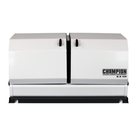
Page 16: General Information
Model 100199 GENERAL INFORMATION COMPONENT IDENTIFICATION – 8.5 KW GENERATOR Figure 1 Exhaust System ATS Control Module Air Inlet Engine Control Module Fuel Regulator/Wire Connections (behind panel) 10. Batteries (not included) Main Circuit Breaker 11. Engine Hour Meter 12. Alternator... -
Page 17: Component Identification - Engine
Model 100199 GENERAL INFORMATION COMPONENT IDENTIFICATION – CONTROL PANEL ENGINE MAIN CIRCUIT BREAKER The 35.5-amp main circuit breaker protects the generator from circuit overload. The main circuit breaker controls total output of the generator. (Figure 3) MAIN CIRCUIT BREAKER Figure 3 1. -
Page 18: Set Exercise Time
Model 100199 GENERAL INFORMATION SET EXERCISE TIME Manual ARRÊT Manuel To set the exercise time, the engine control module switch APAGADO Exercise / Exercice / Manual must be in the ATS mode. Decide on the desired day and time Ejercicio to exercise the generator. -
Page 19: Ats Control Module
Model 100199 GENERAL INFORMATION HIGH ENGINE TEMP LED RUN LED The red LED will be lit if the engine operating temperature The green LED will be lit indicating the engine is running. exceeds the factory preset limits. If excessive operating... -
Page 20: Battery Charger
Model 100199 GENERAL INFORMATION BATTERY CHARGER EMISSION REQUIREMENTS The LEDs on the battery charger indicate the state of the This engine-powered generator meets all United States battery’s charge level. Battery charger rating 24 Vdc 1.6A. Environmental Protection Agency (EPA) Phase 3 requirements (Figure 7) and is approved for use in both the USA and Canada. -
Page 21: Specifications
Model 100199 GENERAL INFORMATION SPECIFICATIONS Home Standby Generator Maximum continuous power, LPG 8.5 kW Maximum continuous power, NG 7.5 kW Rated voltage 120/240 Amps 70.8/35.4 LPG, 62.5/31.25 NG Harmonic distortion Less than 5% Main line circuit breaker 35.5 amp Phase... -
Page 22: Fuel System
Model 100199 GENERAL INFORMATION FUEL SYSTEM BATTERY CHARGING The engine is fitted with a dual master mixer assembly The generator is equipped with an automatic battery charger. The carburetion system, which allows it to run on either NG or charger will sense the battery’s state of charge and automatically LPG. -
Page 23: Enclosure And Access
Model 100199 OPERATION PRE-START CHECKLIST Before operating the generator, review SAFETY section starting on page <?>. To make sure the generator is ready for proper operation, the following items should be checked: ENCLOSURE AND ACCESS • Fuel valve is in the on position Open the enclosure to gain access to the generator and its •... -
Page 24: Maintenance
Model 100199 MAINTENANCE ENGINE OIL Before performing maintenance procedures, review SAFETY section starting on page <?>. Ensure that the ATS and Engine Switches are in the OFF position ENGINE OIL REQUIREMENTS before performing any maintenance or cleaning. Use American Petroleum Institute (API) Service Class SN or better. -
Page 25: Changing The Engine Oil
Model 100199 MAINTENANCE Remove the dipstick. The oil level should be at the FULL Position drain pan under alternator. mark. If necessary, add oil. DO NOT overfill. Loosen hose clamp on oil drain hose and slide drain hose off retaining pin. (Figure 13) Figure 12 1. -
Page 26: Inspect And Clean Engine Air Cleaner
Model 100199 MAINTENANCE INSPECT AND CLEAN ENGINE SPARK PLUG AIR CLEANER Turn the ATS to the OFF position. Turn the engine control module switch to the OFF position. Turn the engine control module switch to the OFF position. Remove the spark plug cable from the spark plug. -
Page 27: Battery Maintenance
Model 100199 MAINTENANCE BATTERY MAINTENANCE If the house or building has been exposed to a flood, it should be inspected by a certified electrician for any electrical problems Turn the engine control module switch to the OFF position. that may occur if the generator is put back into service or if utility power is restored. -
Page 28: Return To Service After Storage
Model 100199 MAINTENANCE RETURN TO SERVICE AFTER STORAGE Make sure the utility power to the transfer switch is off. The engine control module switch and the ATS control module switch should be in the OFF position. Check the engine oil level. Add oil if needed. - Page 29 Model 100199 MAINTENANCE Page intentionally left blank Part No. 101048...
-
Page 30: Engine Parts
Model 100199 MAINTENANCE ENGINE PARTS Part No. 101048... - Page 31 Model 100199 MAINTENANCE Part Number Description Part Number Description 1.5789.0612 Flange Bolt M6 × 12 2.09.004 Circlip, Ø21 × Ø1 47.080100.01.2 Fan Cover, Black 45.050003.00 Pin, Piston 2.02.007 Nut M16 × 1.5 46.050303.02 Ring, Oil 1.5789.0629 Flange Bolt M6 × 29 46.050302.02...
- Page 32 Model 100199 MAINTENANCE Part Number Description Part Number Description 46.040018.00 Rocker Arm, Exhaust Valve 161.133029.00 Metering Jet, Main, LPG 1.97.1.06 Washer Ø6 161.133029.01 Metering Jet, Main, NG 22.040012.00 Screw, Valve Adjustment 161.133030.00 Metering Jet, Idle, LPG 1.6177.1.06 Lock Nut M6, Flange 161.133030.01...
- Page 33 Page intentionally left blank...
-
Page 34: Enclosure And Assemblies
Model 100199 MAINTENANCE ENCLOSURE AND ASSEMBLIES Part No. 101048... - Page 35 Model 100199 MAINTENANCE Part Number Description Part Number Description 1.6177.1.06 Flange Lock Nut M6 161.100006.00 Spring, Muffler 1.5789.0615 Flange bolt, M6 x 15 Flange Bolt M8 x 35, 2.08.119 Muffler Curb Chain Assembly, 161.200507.00 Cover Supportor, Muffler, Bottom, 161.1010005.01.2 Black Top Cover Assembly, Right, 161.200500.61.24...
- Page 36 Model 100199 MAINTENANCE Part Number Description Part Number Description Pressure Reducing Valve, LPG Hose With NPT3/4 161.136000.00 161.130021.01 LPG/NG Nipple Supportor, Pressure 9.1120.001 Screwdriver, Jet 161.200018.00 Reducing Valve Battery Jump Wire, 275 5.1900.074 1.5789.0629 Flange bolt, M6 x 29 mm, 6 AWG 1.5783.0825...
- Page 37 Page intentionally left blank...
-
Page 38: Alternator And Exhaust System
Model 100199 MAINTENANCE ALTERNATOR AND EXHAUST SYSTEM Part No. 101048... - Page 39 Model 100199 MAINTENANCE Part Number Description Part Number Description Foams Ring, Engine Fan, 45.090006.20 Holder, Air Cleaner 161.200021.00.6 Flame Retardant 1.6177.1.10 Flange Lock Nut, M10 1.5789.0608 Flange Bolt, M6 X 8 161.201600.01 Supportor, End Housing 161.200024.00.1 Supportor, Air Guide Cover 161.200605.00...
-
Page 40: Control Panel
Model 100199 MAINTENANCE CONTROL PANEL Part No. 101048... - Page 41 161.210017.00 5.1420.002 Hour Meter Connector 35.5Amp Circuit Breaker, Plastic Conduit, CSA, 5.1240.935 5.1320.017 Double Pole, UL 50mm 1.9074.3.0510 Screw, M5X10 100199.21.10.V1.2 Wire Assembly 5.1850.004 ATS Controller, ATS100 161.230003.00. Decal, Panel,100199 Generator Controller, V1.0 5.1850.003 GTR128 161.230004.00. Decal, Nameplate, 1.5789.0550 Flange Bolt, M5 x 50 V1.0...
-
Page 42: Wiring Diagram
Model 100199 MAINTENANCE WIRING DIAGRAM Part No. 101048... -
Page 43: Troubleshooting
Model 100199 TROUBLESHOOTING TROUBLESHOOTING HSB The number one problem which relates to starting, output and performance is “Fuel Pressure Insufficient”. Utility fuel regulator and pipe sized to small which can be compounded by pipe run distance to long for the size of pipe installed. Confirm fuel pressure to the fuel regulator during No-load and Load operation. - Page 44 Model 100199 TROUBLESHOOTING NO AC OUTPUT HSB set in “TEST” mode Place HSB in AUTO and ATS mode. Circuit breaker in “OFF” position Turn on breaker. ATS control in “OFF” mode Place ATS module in ATS mode. Main circuit breaker in “OFF” position.
-
Page 45: Additional Information
Model 100199 ADDITIONAL INFORMATION IDENTIFY/SELECT STANDBY SURGE PROTECTION CIRCUITS CAUTION IDENTIFY THE BASIC NEEDS Voltage fluctuation may impair the proper functioning of It is very important to understand what items the home owner sensitive electronic equipment. wants powered by the HSB during a utility failure. The selection... -
Page 46: Customer Familiarization Summary
Model 100199 ADDITIONAL INFORMATION CUSTOMER FAMILIARIZATION NOTICE SUMMARY By law it is required in many states to have a Carbon It’s important to educate the home owner on proper Monoxide (CO) detector in operating condition in your maintenance, operation and service call procedures. A properly home. -
Page 47: Hsb, Ats Model & Serial Reference Ats Back-Up Circuits
Model 100199 ADDITIONAL INFORMATION HSB, ATS MODEL & SERIAL REFERENCE ATS BACK-UP CIRCUITS HSB Model Number HSB Serial Number Fuel Type ATS Model Number ATS Serial Number ATS circuits powered Date Installed Dealer/Installer Address Phone Cell Purchased from Part No. 101048... -
Page 48: Maintenance And Service Record
Model 100199 ADDITIONAL INFORMATION MAINTENANCE AND SERVICE RECORD Keeping accurate records when any service is preformed is important. Records replace guessing when a repair was done or when it should be scheduled. Hour Meter notation as well as the date provides better time period records. To maintain the overall performance throughout the life of the product follow the scheduled maintenance chart contained in your owner’s manual or refer to www. - Page 49 Champion Power Equipment 12039 Smith Ave. Santa Fe Springs, CA 90670 USA Made in China...
- Page 50 10 Year Limited Warranty* Basic Warranty Provisions Champion Air-Cooled 8.5kW – 20kW Home Standby Units USA and Canadian Models For a period of 10 years or 2000 hours (whichever occurs first) from successful activation by an Authorized Champion Home Standby Dealer, Champion Power Equipment will, at its option, repair or replace any part(s) which upon examination, inspection and testing by Champion Power Equipment or an Authorized Champion Home Standby Dealer is found to be defective under normal use and service, in accordance with the Warranty Schedule set forth below.
- Page 51 THIS WARRANTY SHALL NOT APPLY TO THE FOLLOWING: Original installation or start-up costs Champion Home Standby generators that utilize non-Champion Power Equipment replacement parts Costs of normal maintenance (i.e. tune-ups, associated part(s), adjustments, loose/leaking clamps, installation and start-up) Units sold, rated or used for "Prime Power", "Trailer Mounted" or "Rental Unit" applications Damage to generator system (including transfer switch) caused by improper installation or costs necessary to correct installation Units used for Prime Power in place of existing utility power (where utility power is present) or in place of utility...
- Page 52 Costs incurred for equipment used for removal and/or reinstallation of generator, (i.e.: cranes, hoists, lifts, etc.) Planes, ferries, railroad, buses, helicopters, snowmobiles, snow-cats, off-road vehicles or any other mode of transport deemed abnormal Starting batteries, fuses, light bulbs, engine fluids, and spark plugs THIS WARRANTY AND THE ATTACHED U.S.
- Page 53 CHAMPION POWER EQUIPMENT, INC. (CPE) AND THE UNITED STATES ENVIRONMENT PROTECTION AGENCY (U.S. EPA) EMISSION CONTROL SYSTEM WARRANTY Your Champion Power Equipment (CPE) engine complies with U.S. EPA emission regulations. YOUR WARRANTY RIGHTS AND OBLIGATIONS: The US EPA AND CPE are pleased to explain the Federal Emission Control Systems Warranty on your 2020 small off-road engine (SORE) and engine powered equipment.
- Page 54 EMISSION CONTROL SYSTEM WARRANTY The following are specific provisions relative to your Emission Control System (ECS) Warranty Coverage. 1. APPLICABILITY: This warranty shall apply to 1997 and later model year small off-road engines (SORE). The ECS Warranty Period shall begin on the date the new engine or equipment is delivered to its original, end-use purchaser, and shall continue for 24 consecutive months thereafter.
- Page 55 EMISSION-RELATED PARTS INCLUDE THE FOLLOWING: (using those portions of the list applicable to the engine) Systems covered by this Parts Description warranty Fuel Metering System Fuel regulator, Carburetor and internal parts Air Induction System Air cleaner, Intake manifold Ignition System Spark plug and parts, Magneto ignition system Exhaust System Exhaust manifold, catalytic converter...
Need help?
Do you have a question about the 100199 and is the answer not in the manual?
Questions and answers