
Subscribe to Our Youtube Channel
Related Manuals for Champion Global Power Equipment 100199


Summary of Contents for Champion Global Power Equipment 100199
- Page 1 DANGER: Not intended for use in critical life support application. REV 20190524 DANGER: Generator must be installed and operated outdoors only.
- Page 2 CALIFORNIA PROPOSITION 65 WARNING Cancer and Reproductive Harm – www.P65Warnings.ca.gov DISCLAIMERS All information, illustrations and specifications in this manual are based on the latest information available at the time of publishing. The illustrations used in this manual are intended as representative reference views only. Products are under a continuous improvement policy.
-
Page 3: Table Of Contents
CONTENTS CONTENTS 14 kW HSB Specifications ..........20 Champion 754cc Engine ..........21 Home Standby Generator ..........5 Champion 754cc Engine Torque Specifications ...21 Parts Included ..............5 Master Mixing Assembly Jets (Carburetor System) ..21 INTRODUCTION ............6 Alternator Overview ............22 HSB Models ..............6 Rotor Assembly ............22 Standard Features, Tailor-Made Solutions .....6 Stator Assembly .............22 General Information,... - Page 4 CONTENTS ATS Fuse Troubleshooting and Testing ......56 Hour Meter ............40 Fuses F2 and F3 ............56 Over Voltage Protection (OVP) ........40 Fuses F4 and F5 ............57 Exercise LED ..............41 Fuse F1 ..............57 Set Exercise Time ............41 Fuse F6 ..............57 AVR = Automatic Voltage Regulator ......41 Manual Transfer Switch ..........57 Engine Relay Module .............42 Top Row ..............42...
-
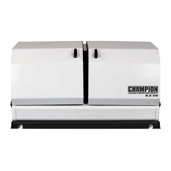
Page 5: Home Standby Generator
CONTENTS PARTS INCLUDED Congratulations on your purchase of a Champion Power Equipment (CPE) home standby generator. This generator is designed and engineered in the USA to exacting standards of the Your HSB ships with the following: North American market. This engine-powered generator meets •... -
Page 6: Introduction
INTRODUCTION HSB MODELS Wattage Model Number Description Section 100199 HSB Generator Only 100947 ATS Only 50A NEMA 1 (non-pre-wired switch) 8.5kW 100950 ATS Only 50A NEMA 3R (non-pre-wired switch) Page 16-17 100174 HSB & 50A ATS NEMA 1 (non-pre-wired switch) 100177 HSB &... -
Page 7: General Information, Standards And Codes
INTRODUCTION GENERAL INFORMATION, ARTICLE X, NATIONAL BUILDING CODE American Insurance Association STANDARDS AND CODES 85 John Street, New York, N.Y. 10038 The following information related to General Information and AGRICULTURAL WIRING HANDBOOK Standards was gathered from the list of publications related Food and Energy Council to installing the HSB generator. -
Page 8: Safety
SAFETY SAFETY SYMBOL DEFINITIONS This is the safety alert symbol. It is used to alert you to potential physical injury hazards. Obey all safety messages that follow this symbol to avoid Black hazard pictorial on yellow possible injury or death. equilateral triangle enclosed by black triangular band The words DANGER, WARNING, CAUTION and NOTICE are used... -
Page 9: Mandatory Actions
SAFETY INSTALLATION HAZARDS Explosion hazard WARNING Have only a qualified electrician or installation technician who is familiar with applicable codes, Burn hazard standards and regulations install and service the generator. ALWAYS comply with local, state and national electrical and building codes when installing the generator. Sever hazard (rotating blade) NEVER alter the recommended installation in a way that would render the unit noncompliant with these... -
Page 10: Before Starting
SAFETY BEFORE STARTING OPERATING HAZARDS CAUTION WARNING ALWAYS operate the generator Before starting, operating and following the manufacturer’s maintaining this generator, be sure instructions. Operating the generator to read and understand the content imprudently, neglecting maintenance and safety messages in this manual. or being careless can result in injury or possible death. -
Page 11: Accidental Starting
SAFETY ACCIDENTAL STARTING CARBON MONOXIDE HAZARDS WARNING DANGER Generator exhaust contains carbon monoxide, a colorless, odorless, poisonous gas. Breathing carbon monoxide will cause nausea, dizziness, fainting or death. If you ALWAYS prevent the generator from starting while the start to feel dizzy or weak, get to covers are open. -
Page 12: Electrical Shock Hazards
SAFETY ELECTRICAL SHOCK HAZARDS FIRE/EXPLOSION HAZARDS WARNING WARNING Use extreme caution when near the generator while it is operating. The generator produces dangerous voltage. NG and LPG are extremely explosive. • Avoid contact with bare wires, terminals and connections while the generator is operating. •... -
Page 13: Entanglement Hazards
SAFETY ENTANGLEMENT HAZARDS SAFETY LABELS WARNING WARNING Use extreme caution when near rotating parts. Rotating parts can All safety labels must be legible to entangle hands, feet, hair, clothing alert personnel of safety hazards. and/or accessories. Traumatic amputation or severe laceration can •... -
Page 14: Safety Labels On Unit
SAFETY SAFETY LABELS ON UNIT Poisonous Gas Hazard Generator exhaust Fire Hazard ALWAYS keep the surrounding contains carbon monoxide. Breathing carbon Burn Hazard DO NOT area near generator clean and free of debris Burn Hazard DO NOT touch hot monoxide will cause nausea, dizziness, and and/or dry vegetation. -
Page 15: Safety, Serial/Model, Nameplate Label Locations
SAFETY SAFETY, SERIAL/MODEL, NAMEPLATE LABEL LOCATIONS The safety labels have specific placement and must be replaced if they are unreadable, damaged or missing. A) Serial number location B) Nameplate C) NFPA 37 Compliance Part No. 101049... -
Page 16: Specifications
SPECIFICATIONS 8.5 KW HSB SPECIFICATIONS Home Standby Generator Maximum continuous power, LPG (Propane) 8.5 kW Maximum continuous power, NG (Natural Gas) 7.5 kW Rated voltage 120/240 Amps 70.8/35.4 LPG, 62.5/31.25 NG Harmonic distortion Less than 5% Main line circuit breaker 35.5 amp Phase Single... -
Page 17: Champion 439Cc Engine
SPECIFICATIONS CHAMPION 439CC ENGINE The 439cc engine was initially developed by Champion for use in Champion portable generators. The single cylinder, overhead design provides high output, efficient operation, low maintenance and demonstrated long life. Based on the engine’s power, performance and reliability, it was selected to power the 8.5kW Champion Home Stand by generator. This engine design has been used in production since 2008. -
Page 18: 11-12.5 Kw Hsb Specifications
SPECIFICATIONS 11-12.5 KW HSB SPECIFICATIONS Home Standby Generator 11 kW 12.5 kW Maximum continuous power, LPG (Propane) 11 kW 12.5 kW Maximum continuous power, NG (Natural Gas) 10 kW 11 kW Rated voltage 120/240 Amps 91.6/45.8 LPG, NG 104/52 LPG, 91.6/45.8 NG Harmonic distortion Less than 5% Main line circuit breaker... -
Page 19: Champion 717Cc Engine
SPECIFICATIONS CHAMPION 717CC ENGINE The 717cc engine was developed by Champion Engine Technology for use in Champion home standby generators. The V-Twin cylinder design provides high output, efficient operation, low maintenance and demonstrated long life. Based on the engine’s power, performance and reliability, it was selected to power the 12.5kW Champion Home Standby Generator. This engine design has been used in production since 2015. -
Page 20: Kw Hsb Specifications
SPECIFICATIONS 14 KW HSB SPECIFICATIONS Home Standby Generator Maximum continuous power, LPG (Propane) 14 kW Maximum continuous power, NG (Natural Gas) 12.5 kW Rated voltage 120/240 Amps 116.6/58.3 LPG, 104/52 NG Harmonic distortion Less than 5% Main line circuit breaker 65 amp Phase Single... -
Page 21: Champion 754Cc Engine
SPECIFICATIONS CHAMPION 754CC ENGINE The 754cc engine was developed by Champion Engine Technology for use in Champion home standby generators. The V-Twin cylinder design provides high output, efficient operation, low maintenance and demonstrated long life. Based on the engine’s power, performance and reliability, it was selected to power the 14kW Champion Home Standby Generator. This engine design has been used in production since 2015. -
Page 22: Alternator Overview
SPECIFICATIONS ALTERNATOR OVERVIEW The alternator is made up with the following major components; Brush holder assembly Rear bearing carrier 2 pole rotor (all copper wire) Stator assembly (all copper wire) Engine adapter ROTOR ASSEMBLY The alternator has a 2-pole rotor, which means the rotor has a single south magnetic pole and a single north magnetic pole. -
Page 23: Unpacking
UNPACKING UNPACKING WARNING The HSB weighs more than 300 lbs. (136 kg). Use the aid of additional assistants and exercise caution during installation. Inspect the generator for damaged or loose parts. DO NOT operate the generator if any components are damaged or loose. Contact your dealer for assistance. -
Page 24: Installation
INSTALLATION Champion HSB units have been run and tested at the There is a HSB sizing guide on Champion web, factory prior to shipment. They do not require any type of www.championpowerequipment.com. break-in period. Before installing the generator, review SAFETY section starting page 8 GENERATOR SIZING Have the generator installed by an authorized CPE dealer. -
Page 25: Placement & Installation Guidelines For Champion Home Standby Generators To Reduce The Risk Of Fire
INSTALLATION PLACEMENT & INSTALLATION GUIDELINES FOR CHAMPION HOME STANDBY GENERATORS TO REDUCE THE RISK OF FIRE NATIONAL FIRE PROTECTION ASSOCIATION (NFPA) STANDARD NFPA 37 REQUIREMENTS AND TESTING REQUIREMENTS: ANNEX A EXPLANATORY MATERIAL NFPA 37 2010, section 4.1.4, Engines Located Outdoors. A.4.1.2 (2) Means of demonstrating compliance are by means of full-scale fire tests or by calculating procedures, such as those Engines, and their weatherproof housings if provided, that are... -
Page 26: Intertek Group Plc Label
INSTALLATION INTERTEK GROUP PLC LABEL LOCATED INSIDE THE GENERATOR, NEXT TO THE GENERATOR’S DATA LABEL ID: 170800364HZH-001 Conforms to / Conforme à: NFPA 37 4.1.4 CL. 2 NFPA® 37 STANDARD FOR THE INSTALLATION AND USE OF STATIONARY COMBUSTION ENGINES AND GAS TURBINE 1193-L-PR-A Colors The National Fire Protection Association (NFPA) standard NFPA 37 establishes criteria for minimizing the hazard of fire during the... -
Page 27: Site Selection, Preparation And Placement
INSTALLATION SITE SELECTION, PREPARATION Watch out for roof overhangs. Snow, ice or rain shouldn’t be permitted to accumulate on the roof and then cascade onto the AND PLACEMENT unit. DANGER These items are important to the overall performance of the HSB generator. -
Page 28: Suggested Preparation
INSTALLATION The back of the HSB locates the fuel and wire entry points. When Compact the fill, this is to provide a firm base for the HSB. placement/mounting is done this side generally faces the closest Remember the final stone level must be 2 or 3 inches higher point to each of those sources. -
Page 29: Installation Preparation
INSTALLATION Once Site Selection, Preparation and Placement has been completed, you can proceed to Installation Preparation. Without these in place you may encounter problems moving forward. There are a number of key items that MUST be addressed prior to the physical installation of the HSB. The installation of the HSB must comply strictly with all applicable codes, standards and regulations (NFPA 37, NFPA 54, NFPA 58, and NFPA 70). -
Page 30: Fuel Requirements And Recommendations
INSTALLATION 1. FUEL REQUIREMENTS AND The HSB engine can run on either NG or LPG. The HSB comes equipped from the factory to run on NG. If your installation RECOMMENDATIONS requires the engine to run on LPG, orifices in the master mixer The following NG and LPG fuel information is provided to assist assembly (carburetor) MUST be changed. -
Page 31: Fuel Consumption
INSTALLATION 2. FUEL CONSUMPTION Fuel Type Percent of Load l/hr – m 1.8 m Air density is less at high altitudes, resulting in less available engine power. Engine power will decrease 3.5% for each 1,000 3.3 m feet (300 m) above sea level and 1% for each 10 degrees F 100% 5.1 m above 77 degrees F. -
Page 32: Lpg Vapor Pipe Sizing
INSTALLATION FLEXIBLE FUEL LINE Refer to the “Fuel Pipe Sizing Chart” contained in this manual or the Installation manual for your specific HSB model. Champion A flexible fuel line (enclosed with the HSB) is to be installed HSB units have been run and tested at the factory prior to between the stationary fuel supply line pipe and the fuel inlet shipment. -
Page 33: Converting To Lpg
INSTALLATION A sediment trap should be installed into the fuel supply pipe line DANGER to drain any condensation. FUEL PIPE SIZING CHART LPG is highly explosive. Even the slightest spark can ignite and cause NOTICE an explosion, which could cause burns or fire resulting in serious Reduced pipe size will affect fuel delivery and performance. - Page 34 INSTALLATION Install the LPG orifices (jets) in the mixing valve clockwise. Remove left side main jet (7), right side main jet (8), left Tighten the low speed orifice (jet) to 15.9 – 22.1 lb.-in. side slow jet (9) and right side slow jet (10). Recommend (1.8 –...
- Page 35 INSTALLATION Connect breather tube (1) to breather port and put clamp (2) on breather tube. Install LPG jets and gasket (6) to fuel inlet chamber. Left side main jet: Size #410 (11) Right side main jet: #430 (12) 14 KW MODELS Left side slow jet: Size #130* (13) Remove breather tube (1) by loosening breather tube Right side slow jet: #120* (14)
-
Page 36: Full Fuel Shut Off
INSTALLATION 7. SEDIMENT TRAP Connect breather tube (1) to breather port and put clamp (2) on breather tube. A sediment trap should be installed into the fuel supply line pipe when using either NG or LPG to drain any condensation. Always make sure the HSB is completely in the OFF position and the full flow fuel shut off valve is closed before removing the sediment trap for drainage. -
Page 37: Battery Requirements, Installation & Service
INSTALLATION Starting (cranking) Cycle Battery is designed to deliver large CAUTION bursts of power for a short time, as needed to start an engine. Starting batteries are intended to have a low depth of discharge Remove the plug, install the Manometer. Open the on each use. - Page 38 INSTALLATION Place the batteries into the built in battery tray. CAUTION Connect one of the black cables (included) from negative (-) terminal of battery 1 to the positive (+) terminal of A battery presents a rick of electrical shock and high battery 2.
-
Page 39: Wire Sizing
INSTALLATION All power cables must enter the enclosure through the knockouts CAUTION provided. If not using knockouts, conduit entry into the enclosure must be at or below knockouts to maintain the Type 3R rating. The electrolyte is a diluted sulfuric acid that is harmful NEMA 3R enclosures are rated and tested for outside installation, to the skin and eyes. -
Page 40: Identify/Select Standby Circuits
INSTALLATION Utility Circuit and Generator Power Connections Install UL1449, CSA-listed, plug-in surge suppressors on the outlets feeding your sensitive equipment. Surge Conductor sizes must be adequate to handle the maximum suppressors come in single or multi-outlet styles. They’re current to which they will be subjected to, based on the 75 designed to protect against virtually all short-duration degrees C column of tables, charts, ect. -
Page 41: Exercise Led
INSTALLATION EXERCISE LED AVR = AUTOMATIC VOLTAGE REGULATOR The GREEN LED will be flashing when the HSB is performing the weekly exercise cycle. When the exercise period has completed, The AVR is an electrical or electronic device that maintains the the LED will stay lit and the HSB will resume standby monitoring. -
Page 42: Engine Relay Module
INSTALLATION Connector #2 (center), has 4 leads. The 2 leads on the right side of the connector (top & bottom) are BLUE. They run to the excitation windings on the stator. The 2 leads on the left side of the connector (top & bottom) are GREEN (top) and WHITE (bottom), they run to the sampling windings of the stator. -
Page 43: Bottom Row
INSTALLATION BOTTOM ROW MODE SWITCH There are 12 wire land points in the bottom row, 8 are the same Manual size, the remaining 4 points are larger, viewed left to right. The ARRÊT Manuel following are the wire land points, function and wire color, this is APAGADO Exercise / Exercice / Manual... - Page 44 INSTALLATION OFF POSITION Once the engine temperature falls into the normal operating range, generally 30 minutes, follow the reset This position closes and shuts down the engine signals. It procedures in the manuals specific to your model to clear prevents the automatic operation of the generator. This position and correct fault.
-
Page 45: Pin Locations
INSTALLATION PIN LOCATIONS Insufficient battery output could result in poor cranking cycles, not permitting the engine starter to reach optimum starting RPM (On backside of the controller) to start the engine. This can be verified by checking the Battery The pins relate to a function of the Engine Controller module. Charger LED, NO CHARGE. -
Page 46: Exterior Warning Led
INSTALLATION DIP SWITCHES ON THE BACK SIDE OF THE CONTROL IN The module will reflect GENSET power when the Generator is BETWEEN THE 2 ROWS OF PIN CONNECTORS the source of power being delivered into the home. The 3 LEDs on the right will be lit (LOAD, ATS active, GENSET, view center to The DIP Switches assist the ECM by setting parameters of right). -
Page 47: Pin Locations
GREEN, RED, viewed left to right. This will eliminate incorrect installation. These are the designated pin locations, function and wire colors for reference; *200 - amp does not apply to model 100199. Pin 1 R (Red) top row (viewed These are factory set delays or activation signals. -
Page 48: Battery Charger
INSTALLATION This unit may be wired to several models of ATS (automatic NO CHARGE / PAS DE CHARGE / transfer switch). The selector switch is located onboard the SIN CARGA POWER generator near the ATS signal wire connector. Select position “1” ALIMENTATION POTENCIA if you are connecting to an ATS50 or ATS100 and select position... -
Page 49: Hsb Test
INSTALLATION With the Engine Control Module and ATS Module both in the OFF position. Turn ON the utility power supply to the ATS. With an AC voltmeter, check for the correct voltage. Single-phase utility power supply. Measure across the UTILITY SUPPLY ATS terminal lugs L1 and L2. Also check L1 to NEUTRAL and L2 to NEUTRAL. -
Page 50: Twin Cylinder Frequency Adjustment
INSTALLATION 10. With an AC voltmeter, check the correct voltage. Single- If no-load frequency is correct but voltage is not, the phase generator supply. voltage regulator (AVR) may require adjustment. Remove the back electrical/fuel access panel. Locate the voltage 11. Measure across GENERATOR SUPPLY ATS lugs L1 and L2. regulator (AVR) on the right inside wall. -
Page 51: Hsb Tests Under Load
INSTALLATION WARNING The manufacturer recommends that a licensed electrician or an individual with complete knowledge of electricity perform these tests. With rated load applied, check voltage and frequency across ATS GENERATOR SUPPLY terminals L1 and L2. Voltage should be greater than 216 Volts. Frequency should be greater than 57 Hertz. -
Page 52: Customer Familiarization Summary
INSTALLATION After starting, the ATS should connect load circuits to the 11. Fill out and provide the customer a copy of the ATS back- GENERATOR SUPPLY. Let the HSB system operate through up circuits. its entire automatic sequence of operation. 12. -
Page 53: Unpacking
INSTALLATION LOCATION AND MOUNTING The ATS module continues to monitor the utility source for the return of utility power. When the utility power returns, the ATS Install the ATS as close as possible to main utility distribution disengages the home from generator power and re-transfers panel. - Page 54 INSTALLATION Strip wires ½ inch and install a Black L1, and Red L2 WARNING wire suitable for 50 amperes between the double-pole feeder breaker in the main panel and the similarly-colored The wires connected to the service terminals on the Utility Supply terminal block in the ATS. main circuit breaker remain LIVE and Install an insulated White wire of the same AWG between HOT.
-
Page 55: Installing Communication Wires
INSTALLATION Strip wire ½ inch and install a Black L1, Red L2, and Position micro Switch TB2-7 G (Green) White neutral wire suitable for 50 amperes between the switch common closure power output connector on the generator(terminal block TB2-8 UNUSED #3) and the similarly-colored terminals on the Generator TB2-9 Load bus line 1 out... -
Page 56: Commissioning The Ats
INSTALLATION ATS CIRCUIT BOARD FUSE INFORMATION WARNING The power from “BOTH” the UTILITY power source and the HSB “MUST” be turned “OFF” before attempting to identified or replace any fuses. Failure to do so could result in serious injury or death. On the backside of the ATS circuit board there are six (6), BUSS COMMISSIONING THE ATS AGC 6 amp fuses. -
Page 57: Fuses F4 And F5
INSTALLATION With the Utility power on, verify the fact that all circuits Connect the negative lead of a 24 VDC power supply to connected to the ATS are energized. Connect an AC terminal 3. voltmeter between terminals 9 and 10. FOR NO MORE THAN 1 SECOND, press the positive lead If the voltmeter reads approximately 240 VAC, fuses F2 of the 24 VDC power supply to terminal 2. -
Page 58: Troubleshooting
TROUBLESHOOTING TROUBLESHOOTING HSB The number one problem which relates to starting, output and performance is “Fuel Pressure Insufficient”. Utility fuel regulator and pipe sized to small which can be compounded by pipe run distance to long for the size of pipe installed. Confirm fuel pressure to the fuel regulator during No-load and Load operation. - Page 59 TROUBLESHOOTING NO AC OUTPUT HSB set in “TEST” mode Place HSB in AUTO and ATS mode. Circuit breaker in “OFF” position Turn on breaker. ATS control in “OFF” mode Place ATS module in ATS mode. Main circuit breaker in “OFF” position. Turn on breaker.
-
Page 60: Hsb And Ats Model & Serial Reference, Ats Back-Up Circuits
HSB AND ATS MODEL & SERIAL REFERENCE, ATS BACK-UP CIRCUITS HSB Model Number _____________________________________ HSB Serial Number _____________________________________ Fuel Type LPG______________ NG_________________ ATS Model Number ______________________________________ ATS Serial Number ______________________________________ ATS circuits powered ______________________________________ ____________________________ ____________________________ ____________________________ ____________________________ ____________________________ ____________________________ ____________________________ ____________________________ ____________________________... - Page 61 Champion Power Equipment 12039 Smith Ave. Santa Fe Springs, CA 90670 USA Made in China...
- Page 62 10 Year Limited Warranty* Basic Warranty Provisions Champion Air-Cooled 8.5kW – 20kW Home Standby Units USA and Canadian Models For a period of 10 years or 2000 hours (whichever occurs first) from successful activation by an Authorized Champion Home Standby Dealer, Champion Power Equipment will, at its option, repair or replace any part(s) which upon examination, inspection and testing by Champion Power Equipment or an Authorized Champion Home Standby Dealer is found to be defective under normal use and service, in accordance with the Warranty Schedule set forth below.
- Page 63 THIS WARRANTY SHALL NOT APPLY TO THE FOLLOWING: Original installation or start-up costs Champion Home Standby generators that utilize non-Champion Power Equipment replacement parts Costs of normal maintenance (i.e. tune-ups, associated part(s), adjustments, loose/leaking clamps, installation and start-up) Units sold, rated or used for "Prime Power", "Trailer Mounted" or "Rental Unit" applications Damage to generator system (including transfer switch) caused by improper installation or costs necessary to correct installation Units used for Prime Power in place of existing utility power (where utility power is present) or in place of utility...
- Page 64 Costs incurred for equipment used for removal and/or reinstallation of generator, (i.e.: cranes, hoists, lifts, etc.) Planes, ferries, railroad, buses, helicopters, snowmobiles, snow-cats, off-road vehicles or any other mode of transport deemed abnormal Starting batteries, fuses, light bulbs, engine fluids, and spark plugs THIS WARRANTY AND THE ATTACHED U.S.
Need help?
Do you have a question about the 100199 and is the answer not in the manual?
Questions and answers