Digi Connect ME Hardware Reference Manual
Hide thumbs
Also See for Connect ME:
- Hardware reference manual (83 pages) ,
- Quick start manual (10 pages) ,
- User manual (201 pages)

Related Manuals for Digi Connect ME


Summary of Contents for Digi Connect ME
- Page 1 Hardware Reference for: Digi Connect ® ® Digi Connect Wi-ME ® Digi Connect ME 9210 Digi Connect Wi-ME 9210 90000897_L...
- Page 2 Digi, Digi International, the Digi logo, a Digi International Company, Digi Connect, Digi Connect ME, Digi Connect Wi-ME, ConnectCore, Digi JumpStart Kit, Net +, NET + OS, NS7520, and NS9210 are trademarks or registered trademarks of Digi International Inc. in the United States and other countries worldwide. All other trademarks are the property of their respective owners.
-
Page 3: Table Of Contents
Contents About This Document................................7 Related Documentation ..............................7 Support Information ..............................7 Chapter 1: About the Digi Connect ME Family of Embedded Modules................8 Digi Connect ME and Wi-ME Embedded Modules ....................9 Types of Modules..............................10 Connectors: Power and Device Interface .........................12 Connectors: Module JTAG Interface ........................14 Connectors: Ethernet Interface..........................16... - Page 4 Radio Frequency Interference (RFI) (FCC 15.105) ..................67 Labeling Requirements (FCC 15.19)......................67 Modifications (FCC 15.21)..........................68 Industry Canada................................68 Declaration of Conformity ............................69 Digi Connect ME and Digi Connect Wi-ME Conformity................69 Digi Connect ME 9210 Conformity .......................70 International EMC Standards ...........................71 Antenna configurations...........................72...
- Page 5 C o n t e n t s Appendix C: Sample Application: PoE Power Supply......................73 2/8 Digi Connect ME............................74 4/8 Digi Connect ME modules and Digi Connect ME 9210 modules ............75 Appendix D: Sample Application: TTL Signals to EIA-232....................76 Appendix E: Change Log ................................. 78 Revision L ................................78...
-
Page 6: About This Document
• • • • • • • • • • • • • • • • • • • • • • • • • • • • • • • • • • • • • • • • • • • • • • • • • • • • • • • • • • • • • • Scope of the Reference Manual The purpose of this document is to enable developers to integrate the Digi Connect ME, Digi Connect ME 9210, or Digi Connect Wi-ME embedded modules with other devices, enabling these devices to make use of the module’s rich networking features. -
Page 7: Chapter 1: About The Digi Connect Me Family Of Embedded Modules
About the Digi Connect ME Family of Embedded Modules This chapter provides information about the modules hardware and contains the following topics: An overview of the Digi Connect ME family of embedded modules "Types of Modules" on page 10 "Connectors: Antenna"... -
Page 8: Digi Connect Me And Wi-Me Embedded Modules
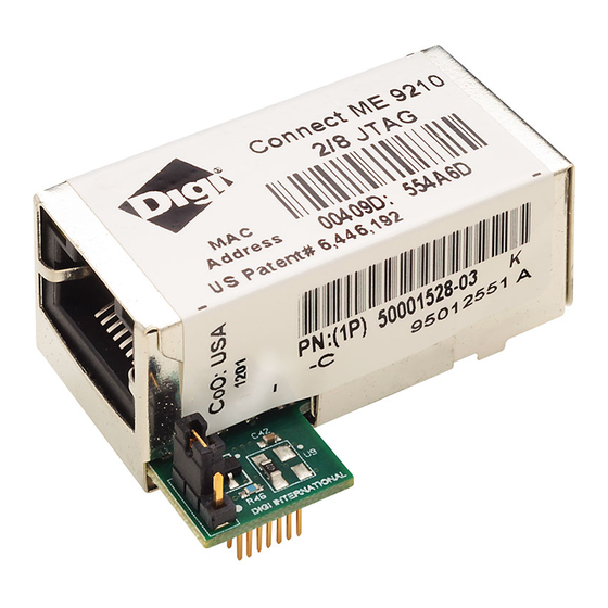
The Digi Connect ME 9210 module is the latest, fully form factor and pin compatible, members of the Digi Connect ME family providing 75 MHz ARM9 core performance based on the Digi NS9210 processor. In addition to... -
Page 9: Types Of Modules
T y p e s o f M o d u l e s Types of Modules There are two types of modules. One module utilizes Digi Plug-and-Play Firmware, while the second is customizable with the option to develop a firmware application in.NET MF or NET+OS. - Page 10 DC-ME-01T-PC (2/8 802.3af compliant -C module) DC-ME-01T-PS (2/8 802.3af compliant -S module) DC-ME-Y402-LX (Digi Connect ME 9210 4/8 Linux - production) DC-ME-Y402-LX-JT (Digi Connect ME 9210 4/8 Linux JTAG - dev only) Digi Connect Wi-ME Modules Model Description Figure Used for development ...
-
Page 11: Connectors: Power And Device Interface
Pin assignments/availability for pins 1 and 2 depend on which module you are using. Pins 1 through 6 are available for Digi Connect ME; these pins are removed for Digi Connect Wi-ME. The pin assignment table shows the appropriate values. - Page 12 Data Carrier Detect (Input) /RESET /RESET Reset +3.3V +3.3V Power Ground Not accessible with Digi Plug-and-Play Firmware. If using a development kit, see 17, 18 11, 12 — "Module Pinout" on page 42 for detailed IO configuration information. — —...
-
Page 13: Connectors: Module Jtag Interface
C o n n e c t o r s : M o d u l e J T A G I n t e r f a c e Connectors: Module JTAG Interface The Module’s JTAG Interface Connector is a 14-pin female vertical header that is labeled P11 on the development board. - Page 14 C o n n e c t o r s : M o d u l e J T A G I n t e r f a c e Module JTAG Interface Connector Pin Assignments JTAG Signal ME JTAG pin # JTAG Connector (P11) pin # +3.3V...
-
Page 15: Connectors: Ethernet Interface
C o n n e c t o r s : E t h e r n e t I n t e r f a c e Connectors: Ethernet Interface The Ethernet connector is an 8-wire RJ-45 jack that meets the ISO 8877 requirements for 10/ 100BASE-T. -
Page 16: Jtag Jumper
C o n n e c t o r s : E t h e r n e t I n t e r f a c e JTAG Jumper The J1 controls the way in which the Digi Connect ME 9210 JTAG device responds to pin 14 being pulled low. -
Page 17: Connectors: Antenna
C o n n e c t o r s : A n t e n n a Connectors: Antenna The Digi Connect Wi-ME is available with 1 RP-SMA connector. The antenna is connected to the module with a reverse polarity SMA connector (sub-miniature size A). The antenna only fits on the module one way to ensure a proper connection. -
Page 18: Module Leds
The following table describes the LEDs. The LEDs are the same for a module with or without a JTAG connector. Note: LED Locations LED Behaviors Digi Plug and Play Firmware Digi Plug and Play Firmware Customizable Digi Connect ME Digi Connect Wi-ME... -
Page 19: Chapter 2: About The Development Board
About the Development Board The development board is a hardware platform from which you can determine how to integrate the embedded modules into your design. The board consists of the following main features: Socket for connecting the embedded modules JTAG connection (for use with the development kit only) ... -
Page 20: Basic Description
B a s i c D e s c r i p t i o n Basic Description The development board contains connectors, switches, and LEDs for use while integrating the embedded module into your design. See the following figure for the location of the connectors, switches, and LEDs. - Page 21 B a s i c D e s c r i p t i o n Board Layout and Connector Locations:...
- Page 22 B a s i c D e s c r i p t i o n Connectors, Switches and LEDs Board Description Markers 1-5 Primary Port Secondary GPIO Switch Prototyping JTAG LEDs, CR5 - Serial Port, P2 Bank, SW3 Area, P4 Header, P12 CR18 Connectors, Switches and LEDs...
- Page 23 B a s i c D e s c r i p t i o n Placement of Module Caution: When handling the development board, wear a grounding wrist strap to avoid ESD damage to the board.
-
Page 24: Port Descriptions
P o r t D e s c r i p t i o n s Port Descriptions The development board provides the following ports: Primary Serial Port, P1 Secondary Serial Port, P2 GPIO Port, P7 See the figure titled "Board Layout and Connector Locations:" on page 22 for the location of the ports. -
Page 25: Secondary Serial Port, P2
The Secondary Serial Port is a DB-9 male connector that is labeled as P2 on the development board. The port is used only with the Digi Connect ME modules with JTAG interfaces for debugging purposes. See the following figure for pin orientation; see the following table for pin assignments. -
Page 26: Gpio Port, P7
P o r t D e s c r i p t i o n s GPIO Port, P7 The GPIO port is a 9-pin male right-angle connector that is labeled as P7 on the development board. See the following figure for pin orientation; see the following tables for pin assignments. For input and output threshold specifications, see "DC Characteristics"... -
Page 27: Connectors And Blocks
JTAG Debugger Connector, P12. -48V DC input to PoE module (Digi Connect ME must be connected to a Powering Device for this feature.), P13 12V DC output from PoE module into Dev Board Power Supply, P14 ... - Page 28 Note that the Digi Connect Wi-ME module does not provide pins 1-6. The GPIO pin numbers mentioned below are used to reference the silkscreen label on the development board, not the actual GPIO number of the Digi Connect Module. See "Module Pinout" on page 42 for detailed IO configuration information.
- Page 29 Power and Device Interface Connector Pin Assignments Signal Description Wi-ME Pin # Function Pin # Function Not accessible with Digi Plug-and-Play Firmware. If using a development 17, 18 11, 12 — kit, see "Module Pinout" on page 42 for detailed IO configuration information. — —...
-
Page 30: Module Jtag Interface Connector, P11
C o n n e c t o r s a n d B l o c k s Module JTAG Interface Connector, P11 The Module’s JTAG Interface Connector is a 14-pin female vertical header that is labeled P11 on the development board. - Page 31 C o n n e c t o r s a n d B l o c k s Module JTAG Interface Connector Pin Assignments JTAG Signal ME JTAG pin # JTAG Connector (P11) pin # +3.3V TRST# SRST +3.3V...
-
Page 32: Jtag Debugger Connector, P12
The JTAG debugger connector is a 20-pin male vertical header that is labeled P12 on the development board. The connector mates with a JTAG debugger plug (for example, a Digi JTAG Link). The connector is used with the development kit only. See the following figure for pin orientation. -
Page 33: Logic Analyzer Header, P3
C o n n e c t o r s a n d B l o c k s Logic Analyzer Header, P3 The Logic Analyzer Header is a 20-pin male vertical header that is labeled P3 on the development board. -
Page 34: Switches And Push Buttons
S w i t c h e s a n d P u s h B u t t o n s Switches and Push Buttons The development board provides the following switches: User PB1 User PB2 GPIO Switch Bank 1, SW3 ... -
Page 35: Reset, Sw4
S w i t c h e s a n d P u s h B u t t o n s Reset, SW4 The Reset switch is a push button switch labeled SW4 on the development board. Pressing the switch holds the embedded module in reset. -
Page 36: Development Board Leds
D e v e l o p m e n t B o a r d L E D s Development Board LEDs The development board contains 25 LEDs that are labeled CR1 through CR25. The following table lists and describes the LEDs. Development Board LED Descriptions Board Indication... - Page 37 D e v e l o p m e n t B o a r d L E D s Development Board LED Descriptions Board Indication Description State Label CR19 GPIO 1 Green Logic 1 Logic 0 CR20 GPIO 2Green Logic 1 Logic 0 CR21...
-
Page 38: Power Jack P15
P o w e r J a c k P 1 5 Power Jack P15 The Power Jack P15 is a barrel connector that accepts 9 to 30 VDC +/- 5%. The following table shows the polarity of the power jack. Power Jack Polarity Contact Polarity... -
Page 39: Test Points
T e s t P o i n t s Test Points The development board provides 13 test points that can be identified by a board label. The test point numbers are in the development board schematic drawings. The following table lists the test point number, board label, and a brief description of each test point. -
Page 40: Chapter 3: Programming Considerations
This chapter provides information programmers may require to make use of some embedded module hardware resources. It provides programming information on the following topics for the Digi Connect ME, the Digi Connect ME 9210, and the Digi Connect Wi-ME: ... -
Page 41: Module Pinout
The NS7520/NS9210 processors support 16 General Purpose I/O (GPIO) lines, some of which are reserved for specific functions and some of which can be customized. For Digi Plug and Play Firmware users, see the Digi Connect Family Users Guide for details on what Pin configurations are available to you. - Page 42 M o d u l e P i n o u t Applies to Digi Connect ME/Wi-ME modules. Applies to Digi Connect ME 9210/Wi-ME 9210 modules. Applies to Digi Connect ME/Wi-ME and ME 9210/Wi-ME 9210 modules. UART GPIO GPIO CAN BUS...
-
Page 43: Module Jtag Interface Pinout
M o d u l e P i n o u t Module JTAG Interface Pinout The following table provides signal header pinout information for the Digi Connect ME JTAG pin and the Development Board JTAG Connector (P11) pin. Module JTAG Interface Connector... -
Page 44: Leds
Ethernet activity. Reset - Hard Reset The Connect ME and ME 9210 modules support a hardware reset via pin 14 of the 20-pin header. The Connect Wi-ME and Wi-ME 9210 modules support a hardware reset via pin 8 of the 14-pin header. -
Page 45: Memory
The Digi Connect ME has the following types of memory. Flash The Digi Connect ME has 2 or 4 MB of flash memory. The Digi Connect Wi-ME has 4 MB or 8 MB of flash memory. On the Digi Connect ME/ARM7 family, the flash memory is controlled by chip select 0, located at 0x02000000. -
Page 46: Appendix A: Module Specifications
11Mbps: -82 dBm Antenna Connector: 1 x RP-SMA The Digi Connect ME and Digi Connect Wi-ME embedded modules were Caution designed for use in no clean flux wave soldering processes. The product is not designed to support draining after a water-wash process, which can lead to water residue inside the enclosure resulting from direct entry or condensation after the wash process. -
Page 47: Serial Interface
Serial Interface One TTL serial interface (CMOS 3.3v) with full modem control signals (DTR, DSR, DCD, RTS, CTS). The Digi Connect ME 9210 also supports SPI and FIM-based application specific interfaces. Data Rates (bps) 50, 75, 110, 134, 150, 200, 300, 600, 1200, 1800, 2400, 4800, 9600, 14400,19200, 28800, 38400,... -
Page 48: Dc Characteristics
DC Characteristics The following tables provide DC characteristics for operating conditions, inputs, and outputs. Operating Conditions Symbol Description Unit Supply Voltage 3.14 3.45 Power Supply Ripple mVpp Digi Connect Digi — Connect Supply Current — 9210 Digi Connect Wi-ME Input Current as “0”... - Page 49 (3657.60 meters) Grounding Recommendation It is recommended that you connect the tabs on the chassis of the Digi Connect ME / Wi-ME, and the ground pins directly to the logic ground plane. It is also recommended that you connect the Digi Connect ME / Wi-ME to the metal chassis of your enclosure.
-
Page 50: Power Management (Digi Connect Me 9210 Only)
P o w e r M a n a g e m e n t ( D i g i C o n n e c t M E 9 2 1 0 o n l y ) Power Management (Digi Connect ME 9210 only) Using the Digi NET+OS development environment, applications on the Digi Connect ME 9210 are capable of operating the module in several reduced power consumption modes. These reduced power operating modes utilize the power management mechanisms for the NS9210 processor for CPU clock scaling and sleep. -
Page 51: Thermal Specifications
T h e r m a l S p e c i f i c a t i o n s Thermal Specifications The table below shows the standard operating temperature ranges for the entire Digi Connect ME family of embedded modules. -
Page 52: Additional Design Recommendations
The host PCB plays a large part in dissipating the heat generated by the module. A large copper plane located under the Digi Connect ME 9210 is soldered to the module’s mounting tabs will improve the heat dissipation capabilities of the PCB. -
Page 53: Dimensions
D i m e n s i o n s Dimensions The following figures show the dimensions of the Digi Connect Wi-ME and Digi Connect ME embedded modules Tolerances Used in Dimensions Figures in this appendix show the dimensions of Digi Connect Wi-ME and Digi Connect ME embedded modules. - Page 54 D i m e n s i o n s Digi Connect Wi-ME Module Front View...
- Page 55 D i m e n s i o n s Side View...
- Page 56 D i m e n s i o n s Bottom View...
-
Page 57: Digi Connect Me Module
D i m e n s i o n s Digi Connect ME Module Front View... - Page 58 D i m e n s i o n s Side View...
- Page 59 D i m e n s i o n s Bottom View...
-
Page 60: Recommended Pcb Layout
Important: The Digi Connect ME has several different product variants with different feature sets. It is strongly recommended that you check the Digi Connect ME product pages on the Digi website for more information on the product variants. Following are several Digi Connect ME product pages;... - Page 61 R e c o m m e n d e d P C B L a y o u t PCB Top Dimensions with JTAG Interface...
-
Page 62: Antenna Information
Part Number DG-ANT-20DP-BG DC-ANT-24DT Any antenna matching the in-band and out-of-band signal patterns and strengths of the antenna, whose characteristics are given in the Antenna Description table and the Radiation Pattern graphic may be used with the Digi Connect Wi-ME. - Page 63 A n t e n n a I n f o r m a t i o n Desktop Antenna Dimensions...
-
Page 64: Rf Exposure Statement
Dipole Antenna Dimensions RF Exposure Statement The Digi Connect Wi-ME module complies with the RF exposure limits for humans as called out in RSS-102. It is exempt from RF evaluation based on its operating frequency of 2.4 GHz, and effective radiated power less than the 3 watt requirement for a mobile device (>20 cm separation) -
Page 65: Safety Statements
S a f e t y S t a t e m e n t s Safety Statements To avoid contact with electrical current: Never install electrical wiring during an electrical storm. Never install an ethernet connection in wet locations unless that connector is specifically ... -
Page 66: Appendix B: Certifications
Radio Frequency Interference (RFI) (FCC 15.105) The Digi Connect ME and Digi Connect Wi-ME embedded modules have been tested and found to comply with the limits for Class B digital devices pursuant to Part 15 Subpart B, of the FCC Rules. -
Page 67: Modifications (Fcc 15.21)
I n d u s t r y C a n a d a Modifications (FCC 15.21) Changes or modifications to this equipment not expressly approved by Digi may void the user's authority to operate this equipment. Industry Canada This digital apparatus does not exceed the Class B limits for radio noise emissions from digital apparatus set out in the Radio Interference Regulations of the Canadian Department of Communications. -
Page 68: Declaration Of Conformity
D e c l a r a t i o n o f C o n f o r m i t y Declaration of Conformity Digi Connect ME and Digi Connect Wi-ME Conformity (In accordance with FCC Dockets 96-208 and 95-19) -
Page 69: Digi Connect Me 9210 Conformity
D e c l a r a t i o n o f C o n f o r m i t y Digi Connect ME 9210 Conformity Manufacturer's Name: Digi International Corporate Headquarters: 11001 Bren Road East Minnetonka MN 55343... -
Page 70: International Emc Standards
Temperature (-40°C to 125°C) Humidity 5% to 90% 12000 feet Altitude (3657.60 meters) The Digi Connect ME and Digi Connect Wi-ME embedded modules meet the following standards: Standards Digi Connect ME Digi Connect Wi-ME Emissions AS/NZS 3548 AS/NZS 3548 CISPR 22 Japan IOH... -
Page 71: Antenna Configurations
The required antenna impedance is [50] ohms The following antenna configurations that were tested with the Connect Wi-ME 802.11 b module. Digi 29000095, Bobbintron SA-006-1, +2 dBi dipole antenna (NP-SMA) PCTEL, MLPV2400NGP, 2.4 GHz, 3dBi gain, no ground place, low profile antenna MAXRAD, MFB24010, 2.4 GHz, 10 dBi Fiberglass OMNI antenna... -
Page 72: Appendix C: Sample Application: Poe Power Supply
Sample Application: PoE Power Supply The following schematics are examples of PoE Power Supplies:... -
Page 73: 2/8 Digi Connect Me
2/8 Digi Connect ME... -
Page 74: 4/8 Digi Connect Me Modules And Digi Connect Me 9210 Modules
4/8 Digi Connect ME modules and Digi Connect ME 9210 modules... -
Page 75: Appendix D: Sample Application: Ttl Signals To Eia-232
Sample Application: TTL Signals to EIA-232 The following schematic is an example of how to convert the modules’s TTL signals to EIA-232. -
Page 77: Appendix E: Change Log
90000631 to 90000897. Revision L In Appendix A, Module Specifications, in Recommended PCB Layout, updated drawings and added links to additional drawings on Digi Connect ME and Wi-ME product pages. Various formatting and pagination changes. Revision K Added additional signal description information to the Module Connector Pin Assignment ... -
Page 78: Revision J
Improved the quality of the PoE Power Supply schematic in Appendix C. Added Digi Connect ME 9210 Declaration of Conformity information to Appendix B. Added revised front view and side view images of the Digi Connect ME and Digi Connect Wi-ME modules to Appendix A. Revision I This revision letter is not used in order to avoid confusion with other letters/numbers which it resembles. -
Page 79: Revision E
Fixed page numbers to make them correspond in PDF form. Added components to Development Board schematics. (#19 and 20) Revision 90000631_G>90000897_A Added Digi Connect ME 9210 related information. Updated schematics in development board chapter to reflect 9210 changes. ... -
Page 80: Revision G
Updated the Connectors: power and device interface section to say that pins 1 and 2 on the connector are available if using Digi Connect ME, not available if using Digi Connect Wi- ME. Updated the Embedded Module Connector table in Chapter 2 similarly.
Need help?
Do you have a question about the Connect ME and is the answer not in the manual?
Questions and answers