Table of Contents
Advertisement
Quick Links
OPERATOR'S MANUAL
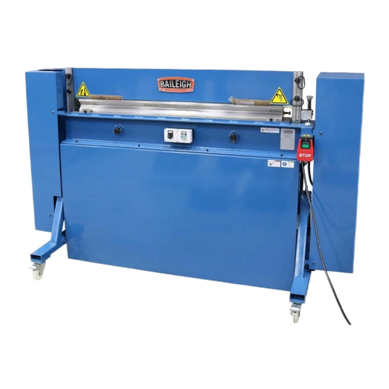
TILTING OPEN BEAM PRESS BRAKE
MODEL: BP-4830
Baileigh Industrial Holdings LLC
P.O. Box 531
Manitowoc, WI 54221-0531
Phone: 920.684.4990
Fax: 920.684.3944
sales@baileigh.com
REPRODUCTION OF THIS MANUAL IN ANY FORM WITHOUT WRITTEN APPROVAL OF BAILEIGH INDUSTRIAL
HOLDINGS LLC IS PROHIBITED. Baileigh Industrial Holdings LLC, Inc. does not assume and hereby disclaims any
liability for any damage or loss caused by an omission or error in this Operator's Manual, resulting from accident,
negligence, or other occurrence.
Rev. 06/2020
© 2020 Baileigh Industrial Holdings LLC
Advertisement
Table of Contents

Related Manuals for Baileigh BP-4830


Summary of Contents for Baileigh BP-4830
- Page 1 REPRODUCTION OF THIS MANUAL IN ANY FORM WITHOUT WRITTEN APPROVAL OF BAILEIGH INDUSTRIAL HOLDINGS LLC IS PROHIBITED. Baileigh Industrial Holdings LLC, Inc. does not assume and hereby disclaims any liability for any damage or loss caused by an omission or error in this Operator’s Manual, resulting from accident, negligence, or other occurrence.
-
Page 2: Table Of Contents
Table of Contents THANK YOU & WARRANTY ..................1 INTRODUCTION ......................3 GENERAL NOTES ......................3 SAFETY INSTRUCTIONS ....................4 SAFETY PRECAUTIONS ....................6 Dear Valued Customer: ....................6 TECHNICAL SPECIFICATIONS ..................8 TECHNICAL SUPPORT ....................8 UNPACKING AND CHECKING CONTENTS ..............9 TRANSPORTING AND LIFTING .................. -
Page 3: Thank You & Warranty
THANK YOU & WARRANTY Thank you for your purchase of a machine from Baileigh Industrial Holdings LLC. We hope that you find it productive and useful to you for a long time to come. Inspection & Acceptance. Buyer shall inspect all Goods within ten (10) days after receipt thereof. Buyer’s payment shall constitute final acceptance of the Goods and shall act as a waiver of the Buyer’s rights to inspect or... - Page 4 We apologize for any discrepancies that may occur. Baileigh Industrial Holdings LLC reserves the right to make any and all changes deemed necessary in the course of business including but not limited to pricing, product specifications, quantities, and product availability.
-
Page 5: Introduction
INTRODUCTION The quality and reliability of the components assembled on a Baileigh Industrial Holdings LLC machine guarantee near perfect functioning, free from problems, even under the most demanding working conditions. However, if a situation arises, refer to the manual first. If a solution cannot be found, contact the distributor where you purchased our product. -
Page 6: Safety Instructions
IMPORTANT PLEASE READ THIS OPERATORS MANUAL CAREFULLY It contains important safety information, instructions, and necessary operating procedures. The continual observance of these procedures will help increase your production and extend the life of the equipment. SAFETY INSTRUCTIONS LEARN TO RECOGNIZE SAFETY INFORMATION This is the safety alert symbol. - Page 7 SAVE THESE INSTRUCTIONS. Refer to them often and use them to instruct others. PROTECT EYES Wear safety glasses or suitable eye protection when working on or around machinery. PROTECT AGAINST NOISE Prolonged exposure to loud noise can cause impairment or loss of hearing.
-
Page 8: Safety Precautions
Baileigh does not recommend or endorse making any modifications or alterations to a Baileigh machine. Modifications or alterations to a machine may pose a substantial risk of injury to the operator or others and may do substantial damage to the machine. - Page 9 4. Remove any adjusting tools. Before operating the machine, make sure any adjusting tools have been removed. 5. Keep work area clean. Cluttered areas invite injuries. 6. Overloading machine. By overloading the machine, you may cause injury from flying parts. DO NOT exceed the specified machine capacities.
-
Page 10: Technical Specifications
(other than die sets and blades). For specific application needs or future machine purchases contact the Sales Department at: sales@baileigh.com, Phone: 920.684.4990, or Fax: 920.684.3944. Note: The photos and illustrations used in this manual are representative only and may not depict the actual color, labeling or accessories and may be intended to illustrate technique only. -
Page 11: Unpacking And Checking Contents
UNPACKING AND CHECKING CONTENTS Your Baileigh machine is shipped complete. Separate all parts from the packing material and check each item carefully. Make certain all items are accounted for before discarding any packing material. WARNING: SUFFOCATION HAZARD! Immediately discard any plastic bags and packing materials to eliminate choking and suffocation hazards to children and animals. -
Page 12: Transporting And Lifting
TRANSPORTING AND LIFTING NOTICE: Lifting and carrying operations should be carried out by skilled workers, such as a truck operator, crane operator, etc. If a crane is used to lift the machine, attach the lifting chain carefully, making sure the machine is well balanced. Follow these guidelines when lifting with truck or trolley: •... -
Page 13: Installation
INSTALLATION IMPORTANT: Consider the following when looking for a suitable location to place the machine: • Overall weight of the machine. • Weight of material being processed. • Sizes of material to be processed through the machine. • Space needed for auxiliary stands, worktables, or other machinery. •... - Page 14 Tank Filling The hydraulic oil is the primary medium for transmitting pressure and also must lubricate the running parts of the pump. After installation of the machine and before machine startup, bring the oil level up to 90% of capacity. Refer to any labels or marking affixed to the outside of the machine, If none exist, use SHELL BRAND #46 or #68 hydraulic oil or an equivalent with similar specifications.
-
Page 15: Getting To Know Your Machine
GETTING TO KNOW YOUR MACHINE... - Page 16 Opens and closes the punch to allow closed bent Punch Opening Cylinder material to be unloaded after bending. Removed to allow the punch to be opened. MUST be installed and tightened during the bending Punch Lock Pins process. Bending without the pins installed and tight will cause damage to the machine.
-
Page 17: Assembly And Set Up
ASSEMBLY AND SET UP WARNING: For your own safety, DO NOT connect the machine to the power source until the machine is completely assembled and you read and understand the entire instruction manual. • The manual depth stop mounts to the back side of the table beam using the two socket head cap screws shipped with the press. -
Page 18: Electrical
3-phase power source other than direct 3-phase. If you are using an alternate power source, consult a certified electrician or contact Baileigh Industrial Holdings LLC prior to energizing the machine. CAUTION: HAVE ELECTRICAL UTILITIES CONNECTED TO MACHINE BY A CERTIFIED ELECTRICIAN! Check if the available power supply is the same as listed on the machine nameplate. - Page 19 WARNING: In all cases, make certain the receptacle in question is properly grounded. If you are not sure, have a qualified electrician check the receptacle • Improper connection of the equipment-grounding conductor can result in risk of electric shock. The conductor with insulation having an outer surface that is green with or without yellow stripes is the equipment-grounding conductor.
-
Page 20: Operation
OPERATION CAUTION: Always wear proper eye protection with side shields, safety footwear, and leather gloves to protect from burrs and sharp edges. When handling large heavy materials make sure they are properly supported. CAUTION: Keep hands and fingers clear of the punch and die area. Stand off to the side of the machine to avoid getting hit with the material during the bending operation. - Page 21 • Place the function selector switch back to the left position for bending material. NOTICE: NEVER operate the press to bend material with the blade open. NEVER operate the press to bend material until all three removable pins are installed and tightened. Operating the press to bend with the pins removed or loose will cause very specific damage to the punch open cylinder and mounts as well as the square column forks.
-
Page 22: Depth Stop Adjustment
Depth Stop Adjustment The depth stop is an adjustable stop bolt which presses on a limit switch to stop the downward travel of the punching beam. This stop then creates a repeatable travel point for the punching beam which in turn creates a repeatable bend for the same material and thickness within the same die opening. -
Page 23: Rotating And Adjusting Die
ROTATING AND ADJUSTING DIE WARNING: Always keep hands and fingers from between the punch and die. The die supplied with the press is heavy. Use the lifting hooks provided. Note: Never install or use dies that are cracked, chipped, or otherwise damaged. Make sure dies are the correct size and type to reduce the risk of overload. -
Page 24: Bending Allowance
BENDING ALLOWANCE To bend sheet metal accurately, you will need to consider the total length of each bend. This is referred to as bend allowance. Subtract the bend allowance from the sum of the outside dimensions of the workpiece to obtain the actual overall length or width of the piece. Because of differences in sheet metal hardness, and whether the bend is made with the grain or against it, exact allowances must sometimes be made by trial and error. -
Page 25: Bending Tonnage Chart
BENDING TONNAGE CHART Width of Thickness of Metal V-Die 26Ga 24Ga 22Ga 20Ga 18Ga 16Ga 14Ga 13Ga 12Ga 11Ga 10Ga 9 Ga Opening .018" .024" .030" .036" .048" .060" .075" .090" .105" .120" .135" .149" .187" .250" 1/8" Typical Die Opening is 8 - 10X material thickness. -
Page 26: Depth Of Bend Setting
DEPTH of BEND SETTING The Depth Stop Blocks will allow for the press to be setup quickly to a previously measured setting which in turn will provide repeatable results. NOTE: Due to material variation (batch lots) it may not be exact. 1. -
Page 27: Depth Of Bend Chart Notes
DEPTH of BEND CHART NOTES 0.75” 1” 1.5” 2” V-Die Width Inches Inches Inches Inches Material Thickness .705” EXAMPLE (16GA) 90°... -
Page 28: Lubrication And Maintenance
LUBRICATION AND MAINTENANCE WARNING: Make sure the electrical disconnect is OFF before working on the machine. Maintenance should be performed on a regular basis by qualified personnel. Always follow proper safety precautions when working on or around any machinery. • Check daily for any unsafe conditions and fix immediately. •... -
Page 29: Parts Diagram
PARTS DIAGRAM... -
Page 30: Parts List
Parts List Item Description Qty. Knob M8 x 35 Gauge Plate Guide Rail of Gauge Hexagon Socket Cap Screw M8 x 16 Flat Washer M8 Hexagon Socket Cap Screw M6 x 10 Flat Washer M6 Back Guard Lower Bending Die Hexagon Bolt M12 x 40 Press Beam Left Guard... - Page 31 Item Description Qty. Set Screw M10 x 45 Hexagon Socket Cap Screw M8 x 20 Adjusting Screw Handle Adjusting Screw Pressure Spring Limit Stop Collar Axis Pin Adjusting Screw Base Hexagon Socket Cap Screw M6 x 60 Hydraulic Motor Upper Bracket for Right Guard Knob M8 x 25 Hexagon Socket Cap Screw M10 x 25 Hexagon Socket Cap Screw M10 x 20...
-
Page 32: Electrical Schematic
ELECTRICAL SCHEMATIC... -
Page 33: Hydraulic Schematic
HYDRAULIC SCHEMATIC... - Page 34 NOTES...
- Page 35 NOTES...
- Page 36 BAILEIGH INDUSTRIAL HOLDINGS LLC 1625 D , WI 54220 UFEK RIVE ANITOWOC : 920. 684. 4990 F : 920. 684. 3944 HONE www.baileigh.com BAILEIGH INDUSTRIAL HOLDINGS LTD. U WIFT OINT WIFT ALLEY NDUSTRIAL STATE UGBY , CV21 1QH U IDLANDS...
Need help?
Do you have a question about the BP-4830 and is the answer not in the manual?
Questions and answers