Table of Contents
Advertisement
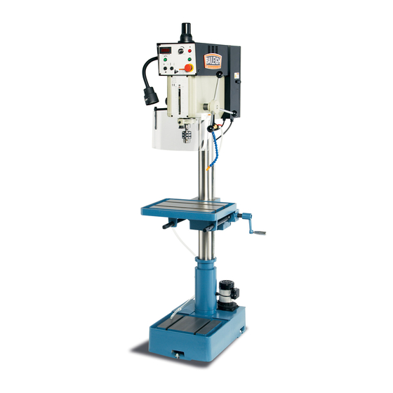
OPERATOR'S MANUAL
VARIABLE SPEED DRILL PRESS
REPRODUCTION OF THIS MANUAL IN ANY FORM WITHOUT WRITTEN APPROVAL OF BAILEIGH INDUSTRIAL, INC.
IS PROHIBITED. Baileigh Industrial, Inc. does not assume and hereby disclaims any liability for any damage or loss
caused by an omission or error in this Operator's Manual, resulting from accident, negligence, or other occurrence.
MODEL: DP-1000VS
Baileigh Industrial, Inc.
P.O. Box 531
Manitowoc, WI 54221-0531
Phone: 920.684.4990
Fax: 920.684.3944
sales@baileighindustrial.com
© 2015 Baileigh Industrial, Inc.
Rev. 3/2015
Advertisement
Table of Contents

Related Manuals for Baileigh DP-1000VS


Summary of Contents for Baileigh DP-1000VS
- Page 1 REPRODUCTION OF THIS MANUAL IN ANY FORM WITHOUT WRITTEN APPROVAL OF BAILEIGH INDUSTRIAL, INC. IS PROHIBITED. Baileigh Industrial, Inc. does not assume and hereby disclaims any liability for any damage or loss caused by an omission or error in this Operator’s Manual, resulting from accident, negligence, or other occurrence.
-
Page 2: Table Of Contents
Table of Contents THANK YOU & WARRANTY ..................1 INTRODUCTION ......................3 GENERAL NOTES ......................3 SAFETY INSTRUCTIONS ....................4 SAFETY PRECAUTIONS ....................7 TECHNICAL SUPPORT ....................9 TECHNICAL SPECIFICATIONS ................... 10 Machine Features ...................... 10 UNPACKING AND CHECKING CONTENTS ..............11 Cleaning ........................ - Page 3 Parts List for Drawings D & E ..................36 PARTS IDENTIFICATION DRAWING F ............... 37 Parts List for Drawing F ..................... 38 PARTS IDENTIFICATION for PUMP ASSEMBLY ............39 Parts List for Pump Assembly..................40 ELECTRICAL SCHEMATIC ..................41 ELECTRICAL ENCLOSURE COMPONENTS .............. 42 Electrical Parts Description ..................
-
Page 4: Thank You & Warranty
THANK YOU & WARRANTY Thank you for your purchase of a machine from Baileigh Industrial. We hope that you find it productive and useful to you for a long time to come. Inspection & Acceptance. Buyer shall inspect all Goods within ten (10) days after receipt thereof. Buyer’s payment shall constitute final acceptance of the Goods and shall act as a waiver of the Buyer’s rights to inspect or... - Page 5 Baileigh Industrial makes every effort to ensure that our posted specifications, images, pricing and product availability are as correct and timely as possible. We apologize for any discrepancies that may occur. Baileigh Industrial reserves the right to make any and all changes deemed necessary in the course of business including but not limited to pricing, product specifications, quantities, and product availability.
-
Page 6: Introduction
After receiving your equipment remove the protective container. Do a complete visual inspection, and if damage is noted, photograph it for insurance claims and contact your carrier at once, requesting inspection. Also contact Baileigh Industrial and inform them of the unexpected occurrence. Temporarily suspend installation. -
Page 7: Safety Instructions
IMPORTANT PLEASE READ THIS OPERATORS MANUAL CAREFULLY It contains important safety information, instructions, and necessary operating procedures. The continual observance of these procedures will help increase your production and extend the life of the equipment. SAFETY INSTRUCTIONS LEARN TO RECOGNIZE SAFETY INFORMATION This is the safety alert symbol. - Page 8 SAVE THESE INSTRUCTIONS. Refer to them often and use them to instruct others. PROTECT EYES Wear safety glasses or suitable eye protection when working on or around machinery. PROTECT AGAINST NOISE Prolonged exposure to loud noise can cause impairment or loss of hearing.
- Page 9 ENTANGLEMENT HAZARD – ROTATING SPINDLE Contain long hair, DO NOT wear jewelry or loose fitting clothing. EMERGENCY STOP BUTTON In the event of incorrect operation or dangerous conditions, the machine can be stopped immediately by pressing the E-STOP button. Twist the emergency stop button clockwise (cw) to reset. Note: Resetting the E-Stop will not start the machine.
-
Page 10: Safety Precautions
SAFETY PRECAUTIONS Metal working can be dangerous if safe and proper operating procedures are not followed. As with all machinery, there are certain hazards involved with the operation of the product. Using the machine with respect and caution will considerably lessen the possibility of personal injury. However, if normal safety precautions are overlooked or ignored, personal injury to the operator may result. - Page 11 11. Do not overreach. Maintain proper footing and balance at all times. DO NOT reach over or across a running machine. 12. Stay alert. Watch what you are doing and use common sense. DO NOT operate any tool or machine when you are tired. 13.
-
Page 12: Technical Support
29. Never leave the machine running while unattended. Turn the power OFF. Do not leave the machine until the spindle comes to a complete stop. 30. Hold the piece part firmly against the table. DO NOT attempt to drill a piece part that does not have a flat surface against the table, or that is not secured by a vise. -
Page 13: Technical Specifications
TECHNICAL SPECIFICATIONS Table Size 18.1" x 14.2" (460 x 360mm) Quill Diameter 2.44" (62mm) Spindle Nose to Table 23.8" (604mm) Spindle Nose to Base 45.3" (1150mm) 150 – 3000 rpm Spindle Speed Spindle Taper MT 3 Table Slot .5" (12.7mm) Tapping Capacity Cast Iron 3/4"... -
Page 14: Unpacking And Checking Contents
UNPACKING AND CHECKING CONTENTS Your Baileigh machine is shipped complete in one crate. Separate all parts from the packing material and check each item carefully. Make certain all items are accounted for before discarding any packing material. WARNING: SUFFOCATION HAZARD! Immediately discard any plastic bags and packing materials to eliminate choking and suffocation hazards to children and animals. -
Page 15: Transporting And Lifting
TRANSPORTING AND LIFTING CAUTION: Lifting and carrying operations should be carried out by skilled workers, such as a truck operator, crane operator, etc. If a crane is used to lift the machine, attach the lifting chain carefully, making sure the machine is well balanced. -
Page 16: Installation
INSTALLATION IMPORTANT: Consider the following when looking for a suitable location to place the machine: Overall weight of the machine. Weight of material being processed. Sizes of material to be processed through the machine. Space needed for auxiliary stands, work tables, or other machinery. ... -
Page 17: Overall Dimensions
OVERALL DIMENSIONS... -
Page 18: Getting To Know Your Machine
GETTING TO KNOW YOUR MACHINE... - Page 19 Motor Cover Contains the motor and drive components Electrical Enclosure Houses the electrical components Down - Feed Handle Controls up-down movement of the spindle Column Supports the table and head Gear Rack Engages the table for height adjustment Handle Table height adjustment at two locations Coolant Pump Pumps coolant to the chuck Base...
- Page 20 DIGITAL INDICATOR 150-3000RPM SPINDLE SPEED Coolant Pump Selector Switch Starts the coolant flow for cutting. Reverse Button Reverses the spindle rotation for tapping only. Digital Indicator Displays the rate of spindle rotation in RPM. Spindle Speed Knob Changes the speed of spindle rotation. Drilling / Tapping Selector Switch Selects the mode of operation: drilling or tapping.
-
Page 21: The Drill Head
The Drill Head The drill head attaches to the top of the column. It houses the motor, spindle, controls, and transfer mechanisms. Attached to it is the electrical enclosure, the protective guard, the work light, and the coolant valve with nozzle. The Work Table The sturdy work table can be positioned at varying heights and rotated 180°... -
Page 22: Electrical
ELECTRICAL CAUTION: HAVE ELECTRICAL UTILITIES CONNECTED TO MACHINE BY A CERTIFIED ELECTRICIAN! Check if the available power supply is the same as listed on the machine nameplate. WARNING: Make sure the grounding wire (green) is properly connected to avoid electric shock. DO NOT switch the position of the green grounding wire if any electrical plug wires are switched during hookup. - Page 23 Check with a qualified electrician or service personnel if the grounding instructions are not completely understood, or if in doubt as to whether the tool is properly grounded. Repair or replace damaged or worn cord immediately. Extension Cord Safety Extension cord should be in good condition and meet the minimum wire gauge requirements listed below: LENGTH...
-
Page 24: Machine Adjustments
MACHINE ADJUSTMENTS Adjusting the Gear Rack Height CAUTION: Failure to lock the collar can result in personal injury or damage to the machine. 1. Raising the table to an adequate working height may require raising the column gear rack. 2. Lock the table by turning crankshaft (I) clockwise (cw). 3. -
Page 25: Operation
OPERATION CAUTION: Always wear proper eye protection with side shields, safety footwear, and leather gloves to protect from burrs and sharp edges. Safety guard must be properly positioned with the limit switch roller in the detent of the adjustable ring or the machine will not run. The electrical enclosure cover must be closed and locked, and the emergency stop button must be reset by turning clockwise (cw). -
Page 26: Removing Tooling From The Spindle
9. Select either the drilling or tapping mode with selector switch (AE). 10. Press start button (AF) to begin spindle DIGITAL INDICATOR rotation. 11. Spindle speed is set with knob (AD) and can 150-3000RPM SPINDLE SPEED be read on the digital indicator (AC). 12. -
Page 27: Material Selection
MATERIAL SELECTION CAUTION: It must be determined by the customer that materials being processed through the machine are NOT potentially hazardous to operator or personnel working nearby. When selecting materials keep these instructions in mind: Material must be clean and dry. (without oil) ... -
Page 28: Lubrication And Maintenance
Enough to clean and Weekly Bare metal surfaces heavy-duty engine oil cover the surface High-performance Multi- Enough to clean and Monthly gear rack on the column Purpose Grease. cover the surface Baileigh B-Cool 20:1 5gal. (118.9L) Coolant system biodegradable metal cutting fluid... -
Page 29: Daily Maintenance
Daily Maintenance Do a general cleaning by removing dust and metal chips from the machine. Top off the coolant reservoir. (80% of full tank capacity) Clean filter screen located on the machine base as often as necessary to maintain coolant flow back to reservoir. -
Page 30: Coolant And Oil Disposal
Drain Oils for Lubricating Coolant Any 10:1 (water to coolant) solution will work, however we recommend Baileigh B-Cool 20:1 (water to coolant) biodegradable metal cutting fluid. It has excellent cooling and heat transfer characteristics, is non-flammable, and extends tool and machine life. Each gallon of concentrate makes 21 gallons of coolant. -
Page 31: Timing Belt Replacement
Timing Belt Replacement This machine is designed with a timing pulley and belt to provide greater braking response and torsion strength. The timing belt should be replaced when the belt is worn or broken. 1. Lockout power to the machine. 2. -
Page 32: Parts Identification Drawing A
PARTS IDENTIFICATION DRAWING A A8-3 A2-1 A21-1 A21-2 A3-1 A15-1 A21 A20-2 A20-1 A19-3 A19-2... -
Page 33: Parts Identification Drawing B
PARTS IDENTIFICATION DRAWING B A8-2 A8-1 A6-4 A6-1 A5-1 A6-3 A6-2 A19-1 A33-1 A26-1... -
Page 34: Parts Identification Drawing C
PARTS IDENTIFICATION DRAWING C A9-1 A20-8 A9-2 A20-9 A20-6 A30-1 A17-1 A31-1 A17-2 A20-5 A20-3 A20-4 A18-1 A20-7 A20-1 A20-2... -
Page 35: Parts List For Drawings A, B, & C
Parts List for Drawings A, B, & C Description Size Qty. Head #MT2 Head #MT3 Pulley cover Plate bracket Electric control box A3-1 Hex. socket cap screw M6x12 Safety door switch Drive pulley 5/16”x3/8” A5-1 Set screw Spindle pulley #MT2 A6-1 Spindle pulley #MT3... - Page 36 A17-2 Set screw M6x1.0 Handle rod A18-1 Knob Right lock sleeve A19-1 Left lock sleeve A19-2 Lock handle 1/2” A19-3 Hex nut Spindle assembly A20-1 Spindle shaft #MT2 A20-2 Spindle shaft #MT3 A20-3 Quill #MT2 A20-4 Quill #MT3 A20-5 Taper roller bearing A20-6 Taper roller bearing A20-7...
-
Page 37: Parts Identification Drawing D
PARTS IDENTIFICATION DRAWING D B10-1... -
Page 38: Parts Identification Drawing E
PARTS IDENTIFICATION DRAWING E B6-1 B5-1 B5-2 B8-1... -
Page 39: Parts List For Drawings D & E
Parts List for Drawings D & E Description Size Qty. Table Column Rack Crank shaft B5-1 Gear bracket B5-2 Hex. socket cap screw M8x1.25 1/4”x1-1/2” Hex. socket cap screw 1/4” B6-1 Hex. nut Column collar 3/8”x1” B8-1 Set screw Lock shaft Lock sleeve B10-1 Spring pin... -
Page 40: Parts Identification Drawing F
PARTS IDENTIFICATION DRAWING F B5-14 B5-13 B5-15 B5-12 B5-16 B5-11 B5-17 B5-1 B5-2 B5-10 B5-9 B5-18 B5-8 B5-3 B5-7 B5-4 B5-6 B5-5... -
Page 41: Parts List For Drawing F
Parts List for Drawing F Description Size Qty. B5-1 Gear bracket B5-2 Hex. socket cap screw M8x35 B5-3 5x5x30 B5-4 Shaft 1/4”x 3/8” B5-5 Gear/set screw 1/4”x3/8” B5-6 Worm gear/set screw B5-7 Worm shaft B5-8 Thrust bearing Hex. soc. c’scr. w/washer B5-9 M6x20 B5-10... -
Page 42: Parts Identification For Pump Assembly
PARTS IDENTIFICATION for PUMP ASSEMBLY... -
Page 43: Parts List For Pump Assembly
Parts List for Pump Assembly Item Description Cover Pump B16-1 Hex nut B16-2 Washer B16-3 Hex cap bolt B16-4 Cord B16-5 Hose nipples B16-6 Worm drive hose clamp B16-7 Discharge tube/hose B16-8 Lock nut B16-9 Valve bracket B16-10 Valve B16-11 Nozzle B16-12 Hex socket cap screw... -
Page 44: Electrical Schematic
ELECTRICAL SCHEMATIC VFD-M 200W 220V... -
Page 45: Electrical Enclosure Components
ELECTRICAL ENCLOSURE COMPONENTS... -
Page 46: Electrical Parts Description
Electrical Parts Description Item Description Size Qty. Contactor Contactor Relay 24VAC Fuse 0.5A Fuse 0.5A Fuse Safety Switch Assembly Delta Inverter (230V) VFD-M 1.5kW, AC Motor Delta Inverter (460V) Transformer 230/440V, 1ph, 50/60Hz, 0.23A / 24V, 2.1A 2hp 460V-200W, 400Ω 2hp 230V-200W, 70Ω... -
Page 47: Troubleshooting
TROUBLESHOOTING WARNING: Make sure the electrical disconnect is OFF before working on the machine. FAULT PROBABLE CAUSE REMEDY Wrong voltage Make sure the machine voltage matches the nameplate. Emergency switch has been pressed. Turn E-Stop switch clockwise (cw) to reset. Wait 10 sec. for the Delta motor Electrical enclosure door controller to reset. - Page 48 Noisy spline. Lubricate spline. Noisy Operation Noisy motor Check motor bearings or loose fan motor. Excessive speed. Reduce speed. Chips not clearing. Use pecking operation to clear chips. Drill or Tool Heats Dull tool. Sharpen tool or replace. up or Burns Work Feed rate too slow.
-
Page 49: Troubleshooting The Inverter
TROUBLESHOOTING THE INVERTER Prior to operating or adjusting any electronic component, qualified personnel must take the following aspects into consideration: Disconnect machine from the power supply. DO NOT use bare hands or metal tools to remove or install sensitive electronic parts. ... - Page 50 Check if grounding is adequate. Replace safety fuses. G.F.F Grounding or safety wire issues. When the display continues to show the same code, contact Baileigh Industrial at (920)684- 4990 Internal EEPROM cannot be read or programmed. C.F1~3 or Current sensor error.
- Page 51 NOTES...
- Page 52 , WI 54220 UFEK RIVE ANITOWOC : 920. 684. 4990 F : 920. 684. 3944 HONE www.baileigh.com BAILEIGH INDUSTRIAL, INC. 1455 S. C , CA 91761 AMPUS VENUE NTARIO : 920. 684. 4990 F : 920. 684. 3944 HONE BAILEIGH INDUSTRIAL LTD. U...
Need help?
Do you have a question about the DP-1000VS and is the answer not in the manual?
Questions and answers