Table of Contents
Advertisement
Quick Links
OPERATOR'S MANUAL
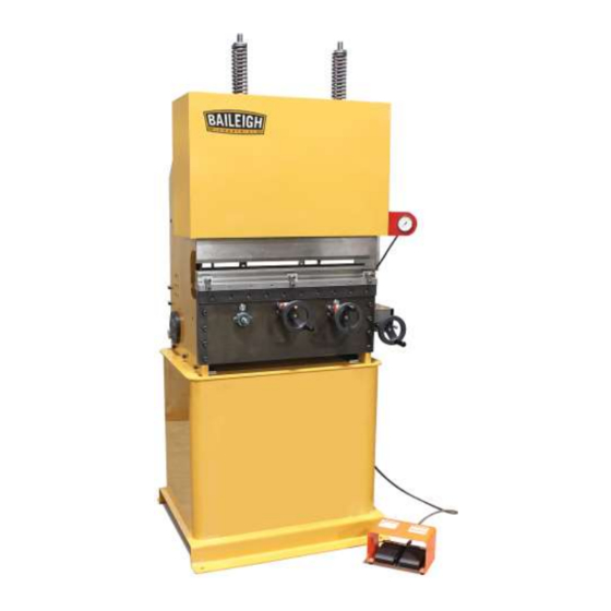
HYDRAULIC PRESS BRAKE
MODEL: BP-3142NC
Baileigh Industrial, Inc.
P.O. Box 531
Manitowoc, WI 54221-0531
Phone: 920.684.4990
Fax: 920.684.3944
sales@baileighindustrial.com
REPRODUCTION OF THIS MANUAL IN ANY FORM WITHOUT WRITTEN APPROVAL OF BAILEIGH INDUSTRIAL, INC.
IS PROHIBITED. Baileigh Industrial, Inc. does not assume and hereby disclaims any liability for any damage or loss
caused by an omission or error in this Operator's Manual, resulting from accident, negligence, or other occurrence.
Rev. 4/2015
© 2015 Baileigh Industrial, Inc.
Advertisement
Table of Contents

Related Manuals for Baileigh BP-3142NC


Summary of Contents for Baileigh BP-3142NC
- Page 1 REPRODUCTION OF THIS MANUAL IN ANY FORM WITHOUT WRITTEN APPROVAL OF BAILEIGH INDUSTRIAL, INC. IS PROHIBITED. Baileigh Industrial, Inc. does not assume and hereby disclaims any liability for any damage or loss caused by an omission or error in this Operator’s Manual, resulting from accident, negligence, or other occurrence.
-
Page 2: Table Of Contents
Table of Contents THANK YOU & WARRANTY ..................1 INTRODUCTION ......................3 GENERAL NOTES ......................3 SAFETY INSTRUCTIONS ....................4 SAFETY PRECAUTIONS ....................6 TECHNICAL SPECIFICATIONS ..................8 TECHNICAL SUPPORT ....................8 UNPACKING AND CHECKING CONTENTS ..............9 Cleaning ........................9 TRANSPORTING AND LIFTING .................. -
Page 4: Thank You & Warranty
THANK YOU & WARRANTY Thank you for your purchase of a machine from Baileigh Industrial. We hope that you find it productive and useful to you for a long time to come. Inspection & Acceptance. Buyer shall inspect all Goods within ten (10) days after receipt thereof. Buyer’s payment shall constitute final acceptance of the Goods and shall act as a waiver of the Buyer’s rights to inspect or... - Page 5 Baileigh Industrial makes every effort to ensure that our posted specifications, images, pricing and product availability are as correct and timely as possible. We apologize for any discrepancies that may occur. Baileigh Industrial reserves the right to make any and all changes deemed necessary in the course of business including but not limited to pricing, product specifications, quantities, and product availability.
-
Page 6: Introduction
INTRODUCTION The quality and reliability of the components assembled on a Baileigh Industrial machine guarantee near perfect functioning, free from problems, even under the most demanding working conditions. However if a situation arises, refer to the manual first. If a solution cannot be found, contact the distributor where you purchased our product. -
Page 7: Safety Instructions
IMPORTANT PLEASE READ THIS OPERATORS MANUAL CAREFULLY It contains important safety information, instructions, and necessary operating procedures. The continual observance of these procedures will help increase your production and extend the life of the equipment. SAFETY INSTRUCTIONS LEARN TO RECOGNIZE SAFETY INFORMATION This is the safety alert symbol. - Page 8 SAVE THESE INSTRUCTIONS. Refer to them often and use them to instruct others. PROTECT EYES Wear safety glasses or suitable eye protection when working on or around machinery. PROTECT AGAINST NOISE Prolonged exposure to loud noise can cause impairment or loss of hearing.
-
Page 9: Safety Precautions
EMERGENCY STOP BUTTON In the event of incorrect operation or dangerous conditions, the machine can be stopped immediately by pressing the E-STOP button. Twist the emergency stop button clockwise (cw) to reset. Note: Resetting the E-Stop will not start the machine. SAFETY PRECAUTIONS Metal working can be dangerous if safe and proper operating procedures are not followed. - Page 10 8. Use the right tool for the job. DO NOT attempt to force a small tool or attachment to do the work of a large industrial tool. DO NOT use a tool for a purpose for which it was not intended.
-
Page 11: Technical Specifications
TECHNICAL SPECIFICATIONS Maximum Pressure 42 tons (38metric tons) Maximum Hydraulic Pressure 3000psi (20.7MPa) Table Length 31" (787mm) Back Gauge Length 19.5" (495mm) Return Speed 1.1"/sec. (28mm/sec.) Stroke Distance, Maximum 2" (50.8mm) Approach Speed 0.9"/sec. (23mm/sec.) Working Speed .4"/sec. (10mm/sec.) Return Speed 0.9"/sec. -
Page 12: Unpacking And Checking Contents
UNPACKING AND CHECKING CONTENTS Your Baileigh machine is shipped complete. Separate all parts from the packing material and check each item carefully. Make certain all items are accounted for before discarding any packing material. WARNING: SUFFOCATION HAZARD! Immediately discard any plastic bags and packing materials to eliminate choking and suffocation hazards to children and animals. -
Page 13: Transporting And Lifting
TRANSPORTING AND LIFTING CAUTION: Lifting and carrying operations should be carried out by skilled workers, such as a truck operator, crane operator, etc. If a crane is used to lift the machine, attach the lifting chain carefully, making sure the machine is well balanced. -
Page 14: Installation
INSTALLATION IMPORTANT: Consider the following when looking for a suitable location to place the machine: • Overall weight of the machine. • Weight of material being processed. • Sizes of material to be processed through the machine. • Space needed for auxiliary stands, work tables, or other machinery. •... -
Page 15: Anchoring The Machine
Anchoring the Machine • Position the machine on a firm and level concrete floor and maintain a safe operating distance around the machine. .31" • Anchor the machine to the floor, as shown in the diagram, (7.87mm) using bolts and expansion plugs or sunken tie rods that connect through holes in the base of the stand. -
Page 16: Getting To Know Your Machine
GETTING TO KNOW YOUR MACHINE... - Page 17 Item Name Description Back stop position This handwheel will adjust the position of the back stop Handwheel. either near or far. Ram Position This handwheel will set your bend angles by controlling the Handwheel. ram end position. Lower Die Material is pressed onto/into the die to create the bend. Upper Punch Presses the material onto/into the die.
-
Page 18: Electrical
ELECTRICAL CAUTION: HAVE ELECTRICAL UTILITIES CONNECTED TO MACHINE BY A CERTIFIED ELECTRICIAN! Check if the available power supply is the same as listed on the machine nameplate. WARNING: Make sure the grounding wire (green) is properly connected to avoid electric shock. DO NOT switch the position of the green grounding wire if any electrical plug wires are switched during hookup. - Page 19 • Check with a qualified electrician or service personnel if the grounding instructions are not completely understood, or if in doubt as to whether the tool is properly grounded. • Repair or replace damaged or worn cord immediately. Extension Cord Safety Extension cord should be in good condition and meet the minimum wire gauge requirements listed below: LENGTH...
-
Page 20: Operation
OPERATION CAUTION: Always wear proper eye protection with side shields, safety footwear, and leather gloves to protect from burrs and sharp edges. CAUTION: Keep hands and fingers clear of the clamping beam. Stand off to the side of the machine to avoid getting hit with the bending apron as it comes up to bend. -
Page 21: General Notes
• The counter reads incrementally in inches of ram travel. These numbers can be documented for every different size of material for future reference of degrees. • Cut some sample material to perform some test bends. • Rotate the ram position (A) CCW and you will watch the ram slowly extend into the lower die opening, these end positions will be relative to bend angles. -
Page 22: Changing And Adjusting Dies
CHANGING AND ADJUSTING DIES Replacing Upper Die WARNING: Always keep hands and fingers from between the dies. The dies supplied with the press are heavy. Have an assistant and a suitable lifting device available. DO NOT try and remove by yourself. Note: Never install or use dies that are cracked, chipped, or otherwise damaged. -
Page 23: Rotating/Replacing Lower Die
Rotating/Replacing Lower Die WARNING: Always keep hands and fingers from between the dies. The dies supplied with the press are heavy. Have an assistant and a suitable lifting device available. DO NOT try and remove by yourself. Note: Never install or use dies that are cracked, chipped, or otherwise damaged. Make sure dies are the correct size and type to reduce the risk of overload. -
Page 24: Punch And Die Specifications
Punch and Die Specifications... -
Page 25: Bending Allowance
BENDING ALLOWANCE In order to bend sheet metal accurately, you will need to consider the total length of each bend. This is referred to as bend allowance. Subtract the bend allowance from the sum of the outside dimensions of the piece part to obtain the actual overall length or width of the piece. Because of differences in sheet metal hardness, and whether the bend is made with the grain or against it, exact allowances must sometimes be made by trial and error. -
Page 26: Lubrication And Maintenance
LUBRICATION AND MAINTENANCE WARNING: Make sure the electrical disconnect is OFF before working on the machine. Maintenance should be performed on a regular basis by qualified personnel. Always follow proper safety precautions when working on or around any machinery. • Check daily for any unsafe conditions and fix immediately. •... -
Page 27: Hydraulic System
Hydraulic System Hydraulic Oil Check the oil level in the tank periodically. Changing the oil after the first 500 working hours. Thereafter, changing the oil after ever 2,000 working hours. Filter Replace the filter with each oil change. Hydraulic Connections Check the entire hydraulic system for leaks daily. -
Page 28: Electrical Schematic
ELECTRICAL SCHEMATIC... -
Page 29: Parts Diagrams
PARTS DIAGRAMS Base Assembly Parts Diagram... -
Page 30: Main Frame Assembly Parts Diagram
Main Frame Assembly Parts Diagram... -
Page 31: Trunnion/Bending Arm Assembly Parts Diagram
Trunnion/Bending Arm Assembly Parts Diagram... -
Page 32: Upper And Lower Ram Assembly Parts Diagram
Upper and Lower Ram Assembly Parts Diagram... -
Page 33: Back Stop Slide Shaft Assembly Parts Diagram
Back Stop Slide Shaft Assembly Parts Diagram... -
Page 34: Back Stop Assembly Parts Diagram
Back Stop Assembly Parts Diagram... -
Page 35: Chain Tensioner Assembly Parts Diagram
Chain Tensioner Assembly Parts Diagram... -
Page 36: Cylinder Assembly Parts Diagram
Cylinder Assembly Parts Diagram... -
Page 37: Travel Limit Assembly Parts Diagram
Travel Limit Assembly Parts Diagram... -
Page 38: Linkage Assembly Parts Diagram
Linkage Assembly Parts Diagram... -
Page 39: Cross Plate Assembly Parts Diagram
Cross Plate Assembly Parts Diagram... -
Page 40: Tooling Assembly Parts Diagram
Tooling Assembly Parts Diagram... -
Page 41: Parts List
Parts List Item Part Number Description Qty. PB24-5A002 PB24 BASE PB24-6A025 ANGLE MOUNT PB24-6A002-V2 SIDE FRAME (L.H.) PB24-6A001-V2 SIDE FRAME (R.H.) M6 X 1.0 X 10 SHCS M12 X 1.75 X 35 SHCS M12 X 1.75 X 20 SHCS M12 X 1.75 X 30 SHCS M5 X 0.8 X 12 SHCS... - Page 42 Item Part Number Description Qty. PB24-7A029 LOWER BEARING HUB PP-1115 M175 POWER UNIT 0500-13 X 2.00 SHCS M12 X 1.75 X 35 HEX FLANGE M8 X 1.25 X 14 HEX FLANGE PB24-7A032 SPACER PB24-7A027-1 ADJUSTING HUB PB24-7A022 WASHER STD. 1.25" EXT. RETAINING RING STD.
- Page 43 Item Part Number Description Qty. PB24-6A011 SLIDE BLOCK PB24-7A013 ACME NUT PB24-6A052 SLIDE BAR PB24-7A006 SLIDE SHAFT PB24-7A031 COUPLING PB24-7A040 EXTENSION SHAFT M10 X 1.5 X 12 SET SCREW M5 X 0.8 X 5 SET SCREW M6 X 1.0 X 8 SET SCREW PB24-7A037 COUNTER SPACER...
- Page 44 Item Part Number Description Qty. PP-1381 3/4-10 THREADED CLAMP COLLAR PB24-6A024 SLIDE GUIDE PB24-6A057 HEIGHT ADJUSTMENT BLOCK PB24-6A058 CURRENT POSITION BLOCK PP-1384 PROXIMITY SWITCH PB24-7A035 STOP INITIATOR PB24-6A048-2 SWITCH GUARD PB24-6A059 POINTER .25-28 GREASE ZERK STRAIGHT GREASE ZERK PB24-6A053 CLAMP BAR (EUROPEAN TOOLING) PB24-7A019 STOP SHAFT PB24-6A032-2...
- Page 45 Item Part Number Description Qty. PB24-6A061 SLIDE KEY BS-0355 5/8 X 1.0" PEG PP-1382 KNOB PB24-6A060 SWITCH ACTUATOR PP-1350 16 TOOTH #35 SPROCKET M16 X 2.0 JAM NUT PB24-5A003 LOWER CYLINDER MOUNT ASSY PB24-5A005 TORQUE LEVER ASSY PP-1354 #40 18T 5/8 BORE SPROCKET PP-1227 0.75 ID X 0.875 OD X 0.75 WIDE PP-1353...
- Page 46 NOTES...
- Page 47 NOTES...
- Page 48 , WI 54220 UFEK RIVE ANITOWOC : 920. 684. 4990 F : 920. 684. 3944 HONE BAILEIGH BAILEIGH INDUSTRIAL, INC. 1455 S. C , CA 91761 AMPUS VENUE NTARIO : 920. 684. 4990 F : 920. 684. 3944 HONE BAILEIGH INDUSTRIAL LTD. U...
Need help?
Do you have a question about the BP-3142NC and is the answer not in the manual?
Questions and answers