Table of Contents
Advertisement
Quick Links
OPERATOR'S
MANUAL
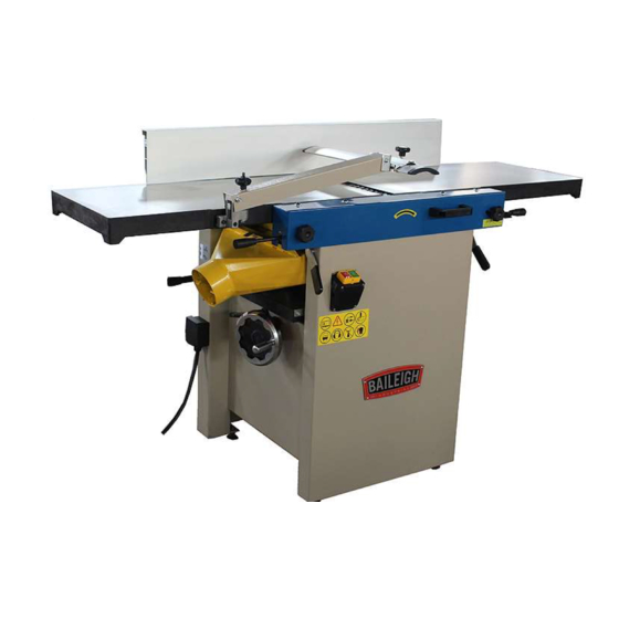
JOINTER / PLANER
MODEL: JP-1250-1.0
Baileigh Industrial, Inc.
P.O. Box 531
Manitowoc, WI 54221-0531
Phone: 920.684.4990
Fax: 920.684.3944
sales@baileigh.com
REPRODUCTION OF THIS MANUAL IN ANY FORM WITHOUT WRITTEN APPROVAL OF BAILEIGH INDUSTRIAL, INC.
IS PROHIBITED. Baileigh Industrial, Inc. does not assume and hereby disclaims any liability for any damage or loss
caused by an omission or error in this Operator's Manual, resulting from accident, negligence, or other occurrence.
Rev. 06/2017
© 2017 Baileigh Industrial, Inc.
Advertisement
Table of Contents
Troubleshooting

Subscribe to Our Youtube Channel
Related Manuals for Baileigh JP-1250-1.0


Summary of Contents for Baileigh JP-1250-1.0
- Page 1 REPRODUCTION OF THIS MANUAL IN ANY FORM WITHOUT WRITTEN APPROVAL OF BAILEIGH INDUSTRIAL, INC. IS PROHIBITED. Baileigh Industrial, Inc. does not assume and hereby disclaims any liability for any damage or loss caused by an omission or error in this Operator’s Manual, resulting from accident, negligence, or other occurrence.
-
Page 2: Table Of Contents
Table of Contents THANK YOU & WARRANTY ..................1 INTRODUCTION ......................3 GENERAL NOTES ......................3 SAFETY INSTRUCTIONS ....................4 SAFETY PRECAUTIONS ....................7 Dear Valued Customer: ....................7 TECHNICAL SPECIFICATIONS ................... 11 TECHNICAL SUPPORT ....................11 UNPACKING AND CHECKING CONTENTS ..............12 Cleaning ........................ - Page 3 Performance Troubleshooting – Planer ..............39 Mechanical Troubleshooting – Planer/Jointer ............40 ELECTRICAL DIAGRAM ....................41 CUTTER BLOCK GUARD AND OUTFEED ASSEMBLY PARTS DIAGRAM ....42 Cutter Block Guard and Outfeed Assembly Parts List ..........43 CUTTER BLOCK ASSEMBLY PARTS DIAGRAM ............45 Cutter Block Assembly Parts List ................
-
Page 4: Thank You & Warranty
THANK YOU & WARRANTY Thank you for your purchase of a machine from Baileigh Industrial. We hope that you find it productive and useful to you for a long time to come. Inspection & Acceptance. Buyer shall inspect all Goods within ten (10) days after receipt thereof. Buyer’s payment shall constitute final acceptance of the Goods and shall act as a waiver of the Buyer’s rights to inspect or... - Page 5 Baileigh Industrial makes every effort to ensure that our posted specifications, images, pricing and product availability are as correct and timely as possible. We apologize for any discrepancies that may occur. Baileigh Industrial reserves the right to make any and all changes deemed necessary in the course of business including but not limited to pricing, product specifications, quantities, and product availability.
-
Page 6: Introduction
After receiving your equipment remove the protective container. Do a complete visual inspection, and if damage is noted, photograph it for insurance claims and contact your carrier at once, requesting inspection. Also contact Baileigh Industrial and inform them of the unexpected occurrence. Temporarily suspend installation. -
Page 7: Safety Instructions
IMPORTANT PLEASE READ THIS OPERATORS MANUAL CAREFULLY It contains important safety information, instructions, and necessary operating procedures. The continual observance of these procedures will help increase your production and extend the life of the equipment. SAFETY INSTRUCTIONS LEARN TO RECOGNIZE SAFETY INFORMATION This is the safety alert symbol. - Page 8 SAVE THESE INSTRUCTIONS. Refer to them often and use them to instruct others. PROTECT EYES Wear safety glasses or suitable eye protection when working on or around machinery. PROTECT AGAINST NOISE Prolonged exposure to loud noise can cause impairment or loss of hearing.
- Page 9 CUTTER HAZARD Keep hands and fingers away from the rotating cutter blades. These rotating cutters can be extremely dangerous if you do not follow proper safety procedures. NEVER place hands directly over or in front of the cutter. Keep hand at least 6” (150mm) from the cutter while operating.
-
Page 10: Safety Precautions
• All Baileigh woodworking machines should be used only for their intended use. • Baileigh does not recommend or endorse making any modifications or alterations to a Baileigh machine. Modifications or alterations to a machine may pose a substantial risk of injury to the operator or others and may do substantial damage to the machine. - Page 11 8. Know the location of the ON - OFF switch. 9. Overloading machine. By overloading the machine you may cause injury from flying parts. DO NOT exceed the specified machine capacities. 10. Dress appropriate. DO NOT wear loose fitting clothing or jewelry as they can be caught in moving machine parts.
- Page 12 26. Make sure machine is disconnected from power supply while motor is being mounted, connected or reconnected. 27. Using Correct Materials. Using materials other than natural wood fiber can result in serious personal injury and machine damage. 28. Warning: The dust generated by certain woods and wood products can be injurious to your health.
- Page 13 41. Feeding the Piece Part. ALWAYS feed the piece part against the rotation of the cutter. NEVER force materials through the shaper. Excessive force against the shaper cutter will cause dangerous kickback conditions and can result in poor cuts. 42. Hand Positioning. NEVER place hands directly over or in front of the cutter. ALWAYS keep hand at least 6”...
-
Page 14: Technical Specifications
(other than die sets and blades). For specific application needs or future machine purchases contact the Sales Department at: sales@baileigh.com, Phone: 920.684.4990, or Fax: 920.684.3944. Note: The photos and illustrations used in this manual are representative only and may not depict the actual color, labeling or accessories and may be intended to illustrate technique only. -
Page 15: Unpacking And Checking Contents
UNPACKING AND CHECKING CONTENTS Your Baileigh machine is shipped complete. Separate all parts from the packing material and check each item carefully. Make certain all items are accounted for before discarding any packing material. WARNING: SUFFOCATION HAZARD! Immediately discard any plastic bags and packing materials to eliminate choking and suffocation hazards to children and animals. -
Page 16: Transporting And Lifting
TRANSPORTING AND LIFTING IMPORTANT: Lifting and carrying operations should be carried out by skilled workers, such as a truck operator, crane operator, etc. If a crane is used to lift the machine, attach the lifting chain carefully, making sure the machine is well balanced. Follow these guidelines when lifting with truck or trolley: •... - Page 17 • Have the work area well illuminated with proper lighting. • Keep the floor free of oil and make sure it is not slippery. • Remove scrap and waste materials regularly, and make sure the work area is free from obstructing objects.
-
Page 18: Getting To Know Your Machine
GETTING TO KNOW YOUR MACHINE DUST-COLLECTING This machine is equipped with a dust collection hood with one port. The dust collector is optional and sold separately. Before the machine is used, make sure the dust collector work as designed. The minimum required air speed at the end of flexible tube is 20 m/sec. The minimum required air volume of the machine is 750 m³/hr. -
Page 19: Electrical
ELECTRICAL CAUTION: HAVE ELECTRICAL UTILITIES CONNECTED TO MACHINE BY A CERTIFIED ELECTRICIAN! Check if the available power supply is the same as listed on the machine nameplate. WARNING: Make sure the grounding wire (green) is properly connected to avoid electric shock. DO NOT switch the position of the green grounding wire if any electrical plug wires are switched during hookup. -
Page 20: Power Cord Connection
• Improper connection of the equipment-grounding conductor can result in risk of electric shock. The conductor with insulation having an outer surface that is green with or without yellow stripes is the equipment-grounding conductor. If repair or replacement of the electric cord or plug is necessary, do not connect the equipment-grounding conductor to a live terminal. -
Page 21: Operating Setup
OPERATING SETUP WARNING: Make sure the electrical disconnect is OFF before working on the machine. Maintenance should be performed on a regular basis by qualified personnel. Always follow proper safety precautions when working on or around any machinery. Cutterhead knives are dangerously sharp. Use extreme caution when working around them. -
Page 22: Planer To Jointer Setup
IMPORTANT: The table is heavy. Use care and if needed an assistant when raising the table. 7. When raised, the table should be in the vertical position as shown in C, Fig. 3. 8. The latch (E, Fig. 3) should be engaged, preventing the table from an accidental forward fall. 9. -
Page 23: Power
Power 1. Once a properly rated plug is connected, plug power cord into outlet. Press the green on button (A, Fig. 4) to start. Press the red off button (B, Fig. 4) to stop. Figure 4 Planer Controls and Adjustments Referring to Figure 5: Power Feed 1. -
Page 24: Jointer Controls And Adjustments
3. Lock the table lock (E). Each revolution of the handwheel (F) results in a 4mm up or down movement of the table (C). A scale on the handwheel column indicates the amount of handwheel rotation. A pointer (B) indicates the table position relative to the cutterhead on the scale (A) located on the side of the cabinet. -
Page 25: Machine Adjustment
1. Loosen the lock knob (J), slide the cutterhead guard (H) into a position to allow the fence to move, then tighten the lock knob. 2. Loosen two fence assembly locking handles (E). 3. Move the entire fence assembly to the desired position; then re-tighten the handles (E). 4. -
Page 26: Jointer Table Lock Handle Adjustment
IMPORTANT: When removing or rotating inserts, clean saw dust from the screw, the insert, and the cutterhead platform. Dust accumulation between these elements can prevent the insert from seating properly, and may affect the quality of the cut. 2. Before installing each screw, lightly coat the screw threads with machine oil and wipe off any excess. -
Page 27: Feed-Roller Belt Replacement
1. Remove the jointer fence assembly (A Fig.9) by first loosening and removing two lock handle assemblies (B). A 4mm hex wrench is helpful, but not necessary. 2. Remove two button head socket screws (C) and upper back panel (D). 3. -
Page 28: Feed Roller Height Adjustment
10. Replace the cutterhead drive belt (F) by looping it around the cutterhead pulley (E), then the larger (outside) motor pulley (M). 11. Slide the motor so the mounting screws (L) rest back in the vertical slot openings, then tighten the mounting screws. 12. -
Page 29: Feed Roller Pressure Adjustment
Feed Roller Pressure Adjustment The pressure of the feed rollers against the workpiece during planing operations is maintained by spring tension. To adjust this tension, turn the socket head screw (B, Figure 15), clockwise to increase pressure, counterclockwise to decrease pressure. Table and Knife Adjustments For accurate jointing, these items must be true: •... - Page 30 5. Place a straight edge (D) across the front of the outfeed table (F) and extending over the infeed table (G). Note the position of the infeed table (G). Note: The position of the straight edge as shown in figure 12 with respect to the fence (H). 6.
- Page 31 Rear adjustment Tools required – 13mm wrench, 4mm hex wrench 1. With a 13mm wrench, loosen the hex cap screws (B1). 2. Using a 4mm hex wrench, make very slight adjustments of 1/8 to 1/4 turns to setscrews (B2) as required.
-
Page 32: Planer Table Adjustment
Planer Table Adjustment WARNING: Make sure the electrical disconnect is OFF before working on the machine. Blades are extremely sharp! Use caution when cleaning or changing. Failure to comply may cause serious injury! Checking Planer Table Parallel to Cutterhead The planer table is set parallel to the cutterhead by the manufacturer and no further adjustment is typically necessary. -
Page 33: Operation
OPERATION CAUTION: Always wear proper eye protection with side shields, safety footwear, and leather gloves to protect from burrs and sharp edges. When handling large heavy material make sure they are properly supported. Initial Start-up After the assembly and adjustments are complete the planer is ready to be tested. Turn on the power supply at the main panel. -
Page 34: Jointing
• If the wood to be jointed is cupped or bowed, place the concave side down, and take light cuts until the surface is flat. • Never surface pieces shorter than 16 inches or thinner than 3/8 inch without the use of a special work holding fixture. -
Page 35: Bevelling
4. Set the infeed table for a cut of approximately 1.5mm. 5. Hold the stock firmly against the fence and table, feed the stock slowly and evenly over the cutterhead. Stock Fence Infeed Table Outfeed Table Figure 20 – Beveling Figure 19 –... -
Page 36: Planer Operations
Planer Operations Depth of Cut Thickness planing refers to the sizing of lumber to a desired thickness while creating a level surface parallel to the opposite side of the board. Board thickness that the planer will produce is indicated by the scale and the depth of-cut gauge. -
Page 37: Preparing The Work
• Avoid knots. Heavily cross-grained wood makes knots hard. Knots can come lose and jam the blade. Any article that encounters planer blades may be forcibly ejected from the planer creating a risk of injury. Preparing the Work • A thickness planer works best when the lumber has at least one flat surface. Use a jointer to create a flat surface. - Page 38 7. Do not push or pull on the workpiece. Move to the rear and receive the planed lumber by grasping it in the same manner that it was fed. To avoid the risk of injury due to kickbacks, do not stand directly in line with the front or rear of the planer. 8.
-
Page 39: Lubrication And Maintenance
LUBRICATION AND MAINTENANCE WARNING: Make sure the electrical disconnect is OFF before working on the machine. Maintenance should be performed on a regular basis by qualified personnel. Always follow proper safety precautions when working on or around any machinery. Daily Maintenance •... -
Page 40: Blade Care
Blade Care WARNING: Make sure the electrical disconnect is OFF before working on the machine. Blades are extremely sharp! Use caution when cleaning or changing. Failure to comply may cause serious injury! • The condition of the blades will affect the precision of the cut. Observe the quality of the cut that the planer produces to check the condition of the blades. -
Page 41: Troubleshooting
TROUBLESHOOTING WARNING: Make sure the electrical disconnect is OFF before working on the machine. Performance Troubleshooting – Jointer Trouble Probable Cause Remedy Finished stock is Knife is higher than Align cutterhead knives with outfeed table. concave on back outfeed table. Setting cutterhead knives. -
Page 42: Performance Troubleshooting - Planer
Performance Troubleshooting – Planer Trouble Probable Cause Remedy Table rollers not set Adjust rollers to proper height Snipe properly. Inadequate support of Support long boards with extension rollers. Note: Snipe long boards. cannot be Uneven feed roller Adjust feed roller tension. eliminated, but can pressure front to back. -
Page 43: Mechanical Troubleshooting - Planer/Jointer
Mechanical Troubleshooting – Planer/Jointer Trouble Probable Cause Remedy Inadequate tension. Adjust chain tension. Chain jumping. Sprockets misaligned. Align sprockets. Sprockets worn. Replace sprockets. Verify unit is connected to power, on-button is No incoming power. pushed in completely, and stop-button is disengaged. -
Page 44: Electrical Diagram
and second, checking the voltage between starter and motor at 220+/-15. If incoming voltage is incorrect, you have a power supply problem. If voltage between starter and motor is incorrect, you have a starter problem. If voltage between starter and motor is correct, you have a motor problem. -
Page 45: Cutter Block Guard And Outfeed Assembly Parts Diagram
CUTTER BLOCK GUARD AND OUTFEED ASSEMBLY PARTS DIAGRAM... -
Page 46: Cutter Block Guard And Outfeed Assembly Parts List
Cutter Block Guard and Outfeed Assembly Parts List Item Part No. Description Specification Qty. JP1686V2-001 Lock Nut JP1686V2-002 Washer JP1686V2-003 Outfeed Table Bracket Shaft JP1250-1.0-004 Outfeed Table Bracket Right JP1686V2-005 Hex. Socket Cap Screw M8x60 JP1250-1.0-006 Eccentric Shaft JP1250-1.0-007 Outfeed/Infeed Table Cutterblock Guard Assembly JP1686V2-008 (#401~#426, #9, #10, #33) - Page 47 Item Part No. Description Specification Qty. JP1686V2-034 Hex. Socket Set Screw JP1686V2-401 Lock Knob JP1686V2-402 Lead Screw JP1686V2-403 Spring JP1250-1.0-404 Bracket for Guard JP1686V2-405 Washer JP1686V2-406 Lock Nut JP1686V2-408 Locking Support JP1686V2-409 Hex. Nut JP1250-1.0-410 Long Shaft JP1686V2-412 Fixed Press Paw JP1686V2-413 Guard Plate Cover JP1686V2-414...
-
Page 48: Cutter Block Assembly Parts Diagram
CUTTER BLOCK ASSEMBLY PARTS DIAGRAM... -
Page 49: Cutter Block Assembly Parts List
Cutter Block Assembly Parts List Item Part No. Description Specification Qty. JP1686V2-060 Hex. Socket Set Screw M6x8 JP1686V2-061 Small Cam Wheel for Safety Switch JP1686V2-062 Washer JP1250-1.0-063 Dust Collector Assembly JP1686V2-064 Pin Roll N5x18 JP1250-1.0-065 Shaft JP1686V2-067 Bearing 6205-2Z Cutterhead, Helical with Inserts (#67, JP1250-1.0HH-071A #71AThru #71D) JP1686V2HH-071B... - Page 50 Item Part No. Description Specification Qty. JP1250-1.0-093 Support Rod JP1250-1.0-094 Outfeed Roller (Rubber) JP1686V2-095 Tube (Powder Metal Bushing) JP1686V2-096 Cutterblock Bracket-Left JP1686V2-097 Wave Washer JP1686V2-098 Retaining Ring CLP52 JP1686V2-099 Washer JP1686V2-100 Drive Chain Sprocket JP1686V2-101 Washer WSH10 JP1686V2-102 Lock Nut JP1686V2-103 Hex.
-
Page 51: Base Assembly Part Diagram
BASE ASSEMBLY PART DIAGRAM... -
Page 52: Base Assembly Parts List
Base Assembly Parts List Item Part No. Description Specification Qty. JP1686V2-131 Carriage Bolt M12x65 JP1686V2-133 Tube JP1686V2-135 Bearing 6001-2Z JP1250-1.0-136P Pulley JP1686V2-137 Lock Nut JP1686V2-138 Pan Head Screw M4x30 JP1686V2-139 Lock Nut JP1686V2-140 Washer JP1686V2-141 Safety Switch JP1686V2-142 Safety Switch Bracket JP1686V2-143 Lock Nut JP1686V2-144... - Page 53 Item Part No. Description Specification Qty. JP1250-1.0-165CC Cabinet Cover (Not Shown) JP1686V2-166 Lock Handle for Infeed Table JP1686V2-167 Infeed Scale JP1686V2-168 Thickness Scale JP1686V2-169 Washer JP1686V2-170 Retaining Ring JP1686V2-172 Hex Socket Head Screw M8x20 JP1250-1.0-177 Cord...
-
Page 54: Infeed Table Assembly Parts Diagram
INFEED TABLE ASSEMBLY PARTS DIAGRAM... -
Page 55: Infeed Table Assembly Parts List
Infeed Table Assembly Parts List Item Part No. Description Specification Qty. JP1686V2-182 Outfeed Table Bracket Shaft JP1250-1.0-184 Infeed Table Bracket Right M8x60 JP1686V2-190 Infeed Table Bracket Left JP1686V2-203 Hex. Socket Cap Screw M8x10 JP1686V2-209 Hex. Socket Cap Screw M8x35 JP1250-1.0-210 Table Stopper JP1686V2-211 Hex. -
Page 56: Drive And Motor Assembly Parts Diagram
DRIVE AND MOTOR ASSEMBLY PARTS DIAGRAM... -
Page 57: Drive And Motor Assembly Parts List
Drive and Motor Assembly Parts List Item Part No. Description Specification Qty. JP1686V2-221 V-Belt for Cutterblock A1194 JP1686V2-222 Drive Chain JP1250-1.0-223 Cam Wheel Bracket JP1686V2-224 Cam Wheel Shaft JP1686V2-225A Plastic Gear Wheel Assembly JP1686V2-226 Bearing 61902 JP1686V2-229 Washer JP1686V2-230 Retaining Ring CLP15 JP1686V2-231 Retaining Ring... -
Page 58: Planer Table Assembly Parts Diagram
PLANER TABLE ASSEMBLY PARTS DIAGRAM... -
Page 59: Planer Table Assembly Parts List
Planer Table Assembly Parts List Item Part No. Description Specification Qty. JP1686V2-288 Indicator JP1686V2-289 Screw M6x12 JP1686V2-291 Thickness Table Guide Bar JP1686V2-292 Hex. Socket Cap Screw M6x20 JP1686V2-293 Guide Bar Bracket JP1686V2-294 Washer JP1686V2-295 Hex. Nut JP1686V2-297 Set Screw M8x12 JP1686V2-298 Indicator Seat JP1686V2-299... - Page 60 Item Part No. Description Specification Qty. JP1686V2-331 Column Support JP1686V2-333 Hex. Socket Set Screw M8x20 JP1686V2-335 Column JP1686V2-336 Hex. Bolt M10x35 JP1686V2-337 Spring Washer JP1250-1.0-338 Thickness Table JP1686V2-339 Loop Counter...
-
Page 61: Working Fence Assembly Parts Diagram
WORKING FENCE ASSEMBLY PARTS DIAGRAM... -
Page 62: Working Fence Assembly Parts List
Working Fence Assembly Parts List Item Part No. Description Specification Qty. JP1686V2-368 Pin for Hinge JP1686V2-369 Square Nut JP1686V2-370 Lock Nut JP1686V2-371 Fence Mounting Bracket JP1686V2-372 Hex. Bolt M8x16 JP1686V2-374 Hex. Socket Cap Screw M6x16 JP1686V2-376 Fence Support-Right JP1686V2-377 Nylon Washer JP1686V2-378 Carriage Bolt M8x25... - Page 63 NOTES...
- Page 64 , WI 54220 UFEK RIVE ANITOWOC : 920. 684. 4990 F : 920. 684. 3944 HONE BAILEIGH BAILEIGH INDUSTRIAL, INC. 1455 S. C , CA 91761 AMPUS VENUE NTARIO : 920. 684. 4990 F : 920. 684. 3944 HONE BAILEIGH INDUSTRIAL LTD. U...
Need help?
Do you have a question about the JP-1250-1.0 and is the answer not in the manual?
Questions and answers